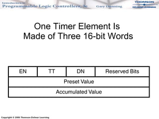
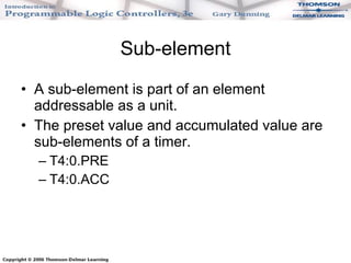
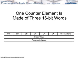
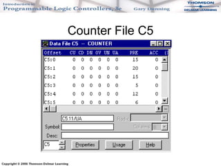
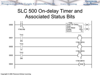
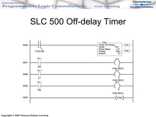
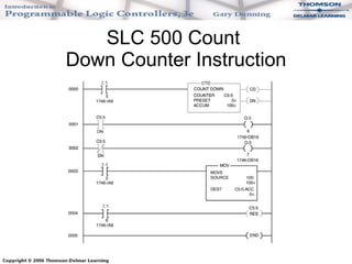
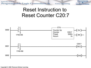
Chapter 16 Timer and Counter Instructions
Objectives Describe the function of an on-delay timer. Describe the function of an off-delay timer. Describe in what instances one would use a retentive timer.  Describe the function of an up counter. Describe the function of a down counter. Describe in what instances one would use an up counter versus a down counter. Define preset, accumulative value, and the timer or counter address. Explain how the various timers and counters are reset.
T4, Timer File The timer file stores only timer elements. An element is a word or group of words that work together as a unit. A timer is made of of three pieces or words. Preset value Accumulated value Status bits The preset value and accumulated value are 16-bit signed integers. Status bits are single bits that make up one 16-bit word. These three words work together as a unit.
One Timer Element Is  Made of Three 16-bit Words
Timer Addressing Sample timer element addressT4:2 T4 = timer file 4 :2 = timer element #2 (0-255 timer elements per file)
Sub-element A sub-element is part of an element addressable as a unit. The preset value and accumulated value are sub-elements of a timer. T4:0.PRE T4:0.ACC
Timer Status Bits Timers have three status bits. Done bit (DN) is true when the accumulated value and preset are equal. Timer timing bit (TT) is true when the timer is timing. Enable bit (EN) is true when the timer instruction is enabled or true.
Timer Bit Addressing Status bit addresses for timer file 4, timer element 2 (T4:2) are listed below: T4:2/DN is the address for the done bit. T4:2/EN is the address for the enable bit. T4:2/TT is the address for the timer timing bit.
Timer File T4
C5, Counter File  (1 of 2) The counter file stores only counter elements. An element is a word or group of words that work together as a unit. A counter is made of three pieces or words. Preset value Accumulated value Status bits
C5, Counter File  (2 of 2) The preset value and accumulated value are 16-bit signed integers. Status bits are single bits that make up one 16-bit word. These three words work together as a unit.
One Counter Element Is  Made of Three 16-bit Words
Counter Addressing Sample counter element address C5:2 C5 = timer file 5 :2 = counter element #2 (0-255 timer elements per file)
Sub-element A sub-element is part of an element addressable as a unit. The preset value and accumulated value are sub-elements of a counter. C5:0.PRE C5:0.ACC
Counter Status Bits  (1 of 2) Counters have five status bits. Done bit (DN) is true when the accumulated value and preset are equal. Count up enable bit (CU) is true when the up counter is true or enabled. Count down enable bit (CD) is true when the count down counter is enabled or true.
Counter Status Bits  (2 of 2) The overflow bit (OV) is true when the up counter has overflowed above +32767. The underflow bit (UN) is true when the down counter has underflowed below -32768. The update accumulator bit (UA) is a high-speed counter status bit for fixed SLC 500 PLCs.
Counter Status Bit Addressing Status bit addresses for counter file 5, counter element 0 (C5:0) are listed below: C5:0/DN is the address for the done bit. C5:0/CU is the address for the count up enable bit. C5:0/CD is the address for the count down enable bit. C5:0/OV is the address for the count up overflow bit. C5:0/UN is the address for the count down underflow bit.
Counter File C5
SLC 500 On-delay Timer
SLC 500 Timer Instructions
SLC 500 On-delay Timer and Associated Status Bits
SLC 500 Off-delay Timer
SLC 500 Retentive Timer
Retentive Timer and  Its Reset Instruction
SLC 500 Counters
SLC 500 Count Up Counter
SLC 500 Count Down Counter
SLC 500 Count  Down Counter Instruction
Reset Instruction to  Reset Counter C20:7
Using the Clear Instruction to Clear C5:0.ACC and C5:1.ACC

Chapter 16 timers and counters

  • 1.
    Chapter 16 Timerand Counter Instructions
  • 2.
    Objectives Describe thefunction of an on-delay timer. Describe the function of an off-delay timer. Describe in what instances one would use a retentive timer. Describe the function of an up counter. Describe the function of a down counter. Describe in what instances one would use an up counter versus a down counter. Define preset, accumulative value, and the timer or counter address. Explain how the various timers and counters are reset.
  • 3.
    T4, Timer FileThe timer file stores only timer elements. An element is a word or group of words that work together as a unit. A timer is made of of three pieces or words. Preset value Accumulated value Status bits The preset value and accumulated value are 16-bit signed integers. Status bits are single bits that make up one 16-bit word. These three words work together as a unit.
  • 4.
    One Timer ElementIs Made of Three 16-bit Words
  • 5.
    Timer Addressing Sampletimer element addressT4:2 T4 = timer file 4 :2 = timer element #2 (0-255 timer elements per file)
  • 6.
    Sub-element A sub-elementis part of an element addressable as a unit. The preset value and accumulated value are sub-elements of a timer. T4:0.PRE T4:0.ACC
  • 7.
    Timer Status BitsTimers have three status bits. Done bit (DN) is true when the accumulated value and preset are equal. Timer timing bit (TT) is true when the timer is timing. Enable bit (EN) is true when the timer instruction is enabled or true.
  • 8.
    Timer Bit AddressingStatus bit addresses for timer file 4, timer element 2 (T4:2) are listed below: T4:2/DN is the address for the done bit. T4:2/EN is the address for the enable bit. T4:2/TT is the address for the timer timing bit.
  • 9.
  • 10.
    C5, Counter File (1 of 2) The counter file stores only counter elements. An element is a word or group of words that work together as a unit. A counter is made of three pieces or words. Preset value Accumulated value Status bits
  • 11.
    C5, Counter File (2 of 2) The preset value and accumulated value are 16-bit signed integers. Status bits are single bits that make up one 16-bit word. These three words work together as a unit.
  • 12.
    One Counter ElementIs Made of Three 16-bit Words
  • 13.
    Counter Addressing Samplecounter element address C5:2 C5 = timer file 5 :2 = counter element #2 (0-255 timer elements per file)
  • 14.
    Sub-element A sub-elementis part of an element addressable as a unit. The preset value and accumulated value are sub-elements of a counter. C5:0.PRE C5:0.ACC
  • 15.
    Counter Status Bits (1 of 2) Counters have five status bits. Done bit (DN) is true when the accumulated value and preset are equal. Count up enable bit (CU) is true when the up counter is true or enabled. Count down enable bit (CD) is true when the count down counter is enabled or true.
  • 16.
    Counter Status Bits (2 of 2) The overflow bit (OV) is true when the up counter has overflowed above +32767. The underflow bit (UN) is true when the down counter has underflowed below -32768. The update accumulator bit (UA) is a high-speed counter status bit for fixed SLC 500 PLCs.
  • 17.
    Counter Status BitAddressing Status bit addresses for counter file 5, counter element 0 (C5:0) are listed below: C5:0/DN is the address for the done bit. C5:0/CU is the address for the count up enable bit. C5:0/CD is the address for the count down enable bit. C5:0/OV is the address for the count up overflow bit. C5:0/UN is the address for the count down underflow bit.
  • 18.
  • 19.
  • 20.
    SLC 500 TimerInstructions
  • 21.
    SLC 500 On-delayTimer and Associated Status Bits
  • 22.
  • 23.
  • 24.
    Retentive Timer and Its Reset Instruction
  • 25.
  • 26.
    SLC 500 CountUp Counter
  • 27.
    SLC 500 CountDown Counter
  • 28.
    SLC 500 Count Down Counter Instruction
  • 29.
    Reset Instruction to Reset Counter C20:7
  • 30.
    Using the ClearInstruction to Clear C5:0.ACC and C5:1.ACC