Downloaded 268 times
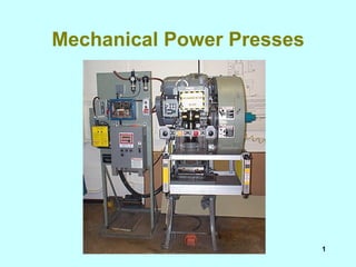


The document summarizes safety requirements for mechanical power presses. It discusses the different types of presses including full and part revolution clutches. It describes requirements for controls, safeguarding devices like two-hand controls, light curtains, and pullbacks. Proper installation and maintenance of these safety systems is required to prevent worker injuries at power presses.