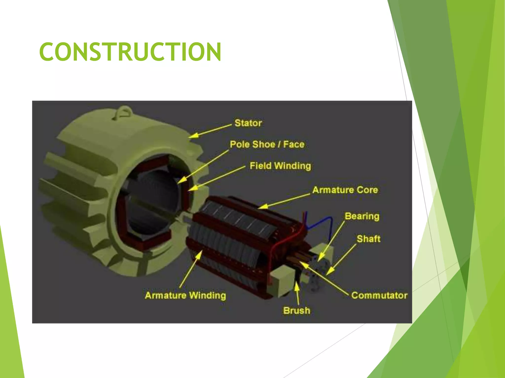
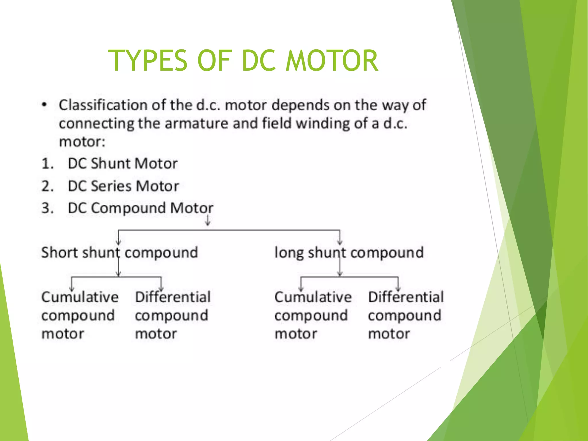
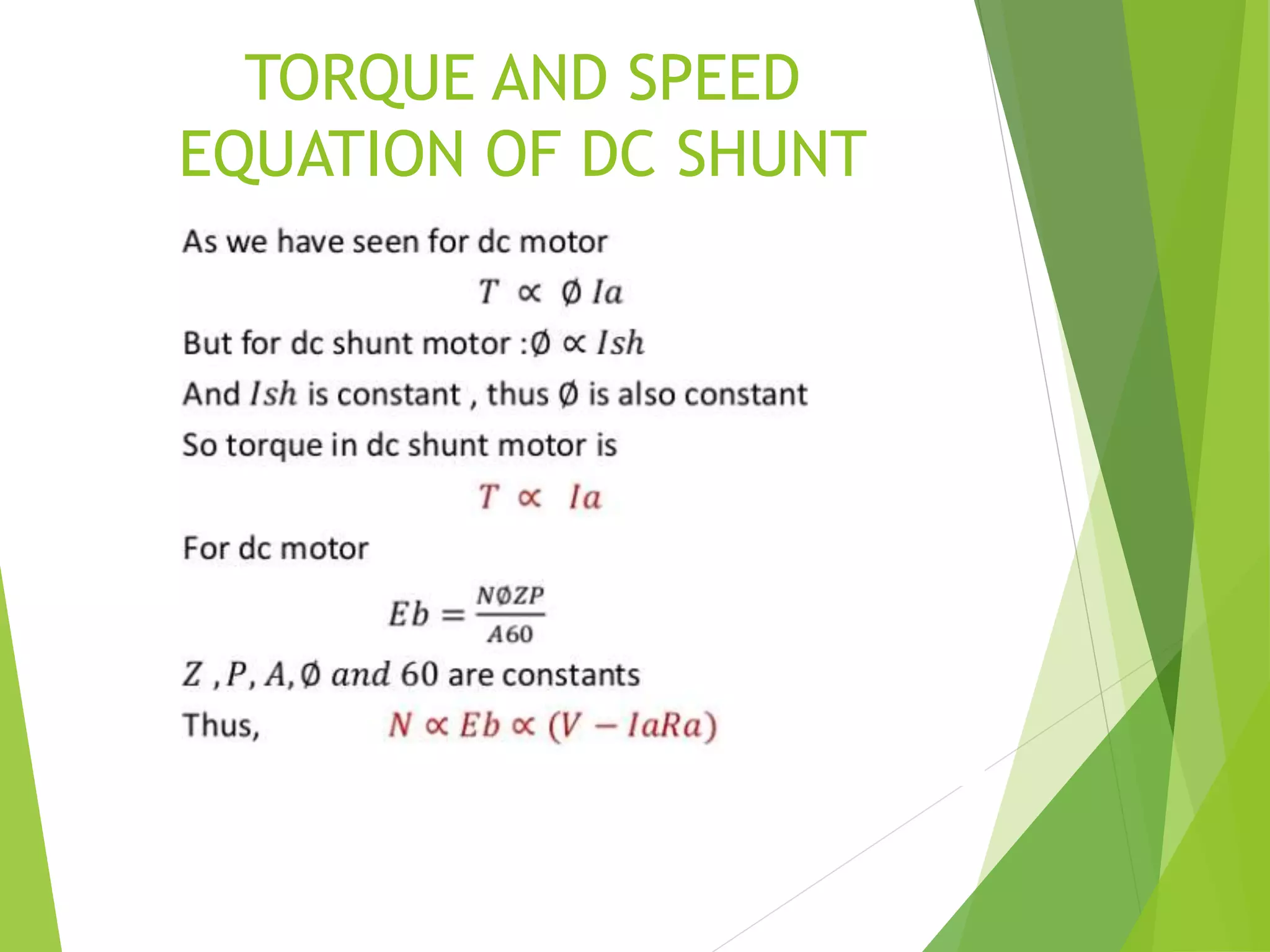
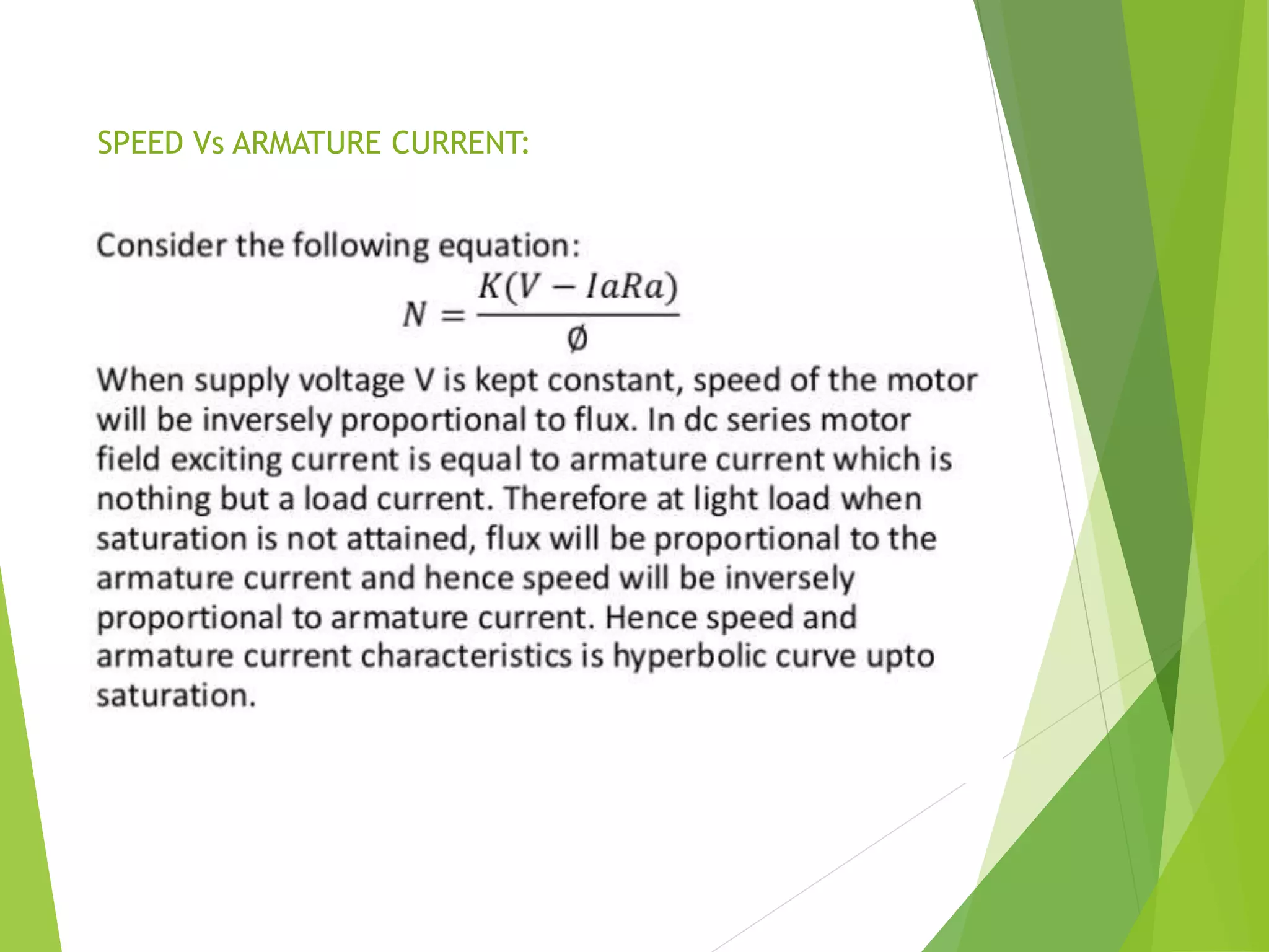
2. MACHINES
Electric Generator: Mechanical Energy Electrical
energy.
Electrical Motor: Electrical Energy Mechanical Energy
3. PRINCIPLE OF DC MOTOR
ELECTIRCAL ENERGYMECHANICAL ENERGY
According to Faraday’s law of electromagnetic
induction, ‘When a current carrying conductor is placed
in a magnetic field it experience a force’.
5. MAJOR COMPONENTS
1. Frame and Yoke
2. Poles
3. Armature
4. Field winding
5. Commutator
6. Brush
7. Other mechanical parts
6. FRAME AND YOKE
It is outer cover of dc motor also called as frame.
It provides protection to the rotating and other part of the
machine from moisture, dust etc.
Yoke is an iron body which provides the path for the flux to
complete the magnetic circuit.
It provides the mechanical support for the poles.
Material Used: low reluctance material such as cast iron, silicon
steel, rolled steel, cast steel etc.
7. POLES AND POLE CORE
Poles are electromagnet, the field winding is wound over it.
It produces the magnetic flux when the field winding is
excited.
The construction of pole is done using the lamination of
particular shape to reduce the power loss due to eddy current.
8. POLE SHOE
Pole shoe is an extended part of a pole.
Due to its typical shape, it enlarges the area of the pole, so
that more flux can pass through the air gap to armature.
Material Used: low reluctance magnetic material such as cast
steel or cast iron is used for construction of pole and pole
shoe.
9. FIELD WINDING
Field coil wound on pole
The coil wound on the pole core are called field coils.
Field coils are connected in series to form field winding.
Current is passed through the field winding in a specific
direction, to magnetize the poles and pole shoes. Thus
magnetic flux is produce in the air gap between the
pole shoe and armature.
Field winding is also called as Exciting winding.
Material Used for copper conductor is copper.
Due to the current flowing through the field winding
alternate N and S poles are produced.
10. ARMATURE CORE
Armature core is a cylindrical drum mounted on the
shaft.
It is provided with large number of slots all over its
periphery and it is parallel to the shaft axis.
Armature conductors are placed in these slots.
Armature core provides low reluctance path to the flux
produced by the field winding.
Material used: high permeability, low reluctance cast
steel or cast iron material is used.
Laminated construction of iron core is used to minimize
the eddy current losses.
11. ARMATURE WINDING
Armature conductor is placed in a armature slots
present on the periphery of armature core.
Armature conductor are interconnected to form the
armature winding.
When the armature winding is rotated using a prime
mover, it cuts the magnetic flux lines and voltage gets
induced in it.
Armature winding is connected to the external circuit
(load) through the commutator and brushes.
Material Used: Armature winding is suppose to carry the
entire load current hence it should be made up of
conducting material such as copper.
12. COMMUTATOR
It is a cylindrical drum mounted on the shaft along with
the armature core.
It is made up of large number of wedge shaped
segments of hard-drawn copper.
The segments are insulated from each other by thin
layer of mica.
Armature winding are tapped at various points and
these tapping are successively connected to various
segments of the commutator.
Function of commutator: • It converts the ac emf
generated internally into dc • It helps to produce
unidirectional torque.
Material Used: it is made up of copper and insulating
material between the segments is mica.
13. BRUSHES
Current are conducted from the armature to the
external load by the carbon brushes which are held
against the surface of the commutator by springs.
Function of brushes: To collect the current from the
commutator and apply it to the external load in
generator, and vice versa in motor.
Material Used: Brushes are made of carbon and they are
rectangular in shape.
14. BACK EMF
When a motor rotates, the conductors housed in the
armature also rotate and cut the magnetic lines of
force. So an emf is induced in the armature conductors
and this induced emf opposes the supply voltage as per
Lenz’s law. This induced emf is call Back emf(or)
counter emf.
15. TORQUE EQUATION
Mechanical power required to rotate the shaft on
mechanical side = 𝑇𝜔………………………………………………
T =Torque in Newton-meter
𝜔= angular velocity in radian /second
Gross mechanical power produced by the motor on
electrical side = 𝐸𝑏𝐼𝑎………………………………………………
Eb = back emf in volts
Ia = armature current in ampere
Equating equation and , ,
we get , 𝐸𝑏𝐼𝑎 = 𝑇𝜔………………………………………………..
1
2
1 2
3
18. WORKING OF DC MOTOR
The direction of the force is given by Fleming's left hand
rule and it's magnitude is given by F = BIL. Where,
B = magnetic flux density,
I = current and
L = length of the conductor within the magnetic field.
Fleming's left hand rule: If we stretch the index(first)
finger, middle(second) finger and thumb of our left hand to
be perpendicular to each other and the direction of
magnetic field is represented by the index(first) finger,
direction of the current is represented by middle(second)
finger then the thumb represents the direction of the force
experienced by the current carrying conductor.
19. Above animation helps in understanding the working
principle of a DC motor. When armature windings are
connected to a DC supply, current sets up in the winding.
Magnetic field may be provided by field winding
(electromagnetism) or by using permanent magnets. In this
case, current carrying armature conductors experience
force due to the magnetic field, according to the principle
stated above.
Commutator is made segmented to achieve unidirectional
torque. Otherwise, the direction of force would have
reversed every time when the direction of movement of
conductor is reversed the magnetic field.
This is how a DC motor works!
21. DC SHUNT MOTOR
In dc shunt motor the armature
and field winding are connected in
parallel across the supply voltage
The resistance if the shunt winding
Rsh is always higher than the armature winding Ra
Since V and Rsh both remains constant the Ish remains
essentially constant, as field current is responsible for
generation of flux.
thus
So shunt motor is also called as constant flux motor.
ф α Ish
22. Eb= VL – Ia Ra
Ia= IL + Ish
VL = Eb + Ia Ra
Ish = VL
Rsh
24. CHARACTERISTIS OF DC
SHUNT MOTOR
To study the performance of the DC shunt Motor
various types of characteristics are to be studied.
1. Torque Vs Armature current characteristics.
2. Speed Vs Armature current characteristics.
3. Speed Vs Torque characteristics.
29. DC SERIES MOTOR
In series wound motor the field winding is
connected in series with the armature.
Therefore, series field winding carries
the armature current.
Since the current passing through a series field winding is the
same as the armature current, series field windings must be
designed with much fewer turns than shunt field windings for
the same mmf.
Therefore, a series field winding has a relatively small
number of turns of thick wire and, therefore, will possess a
low resistance.
30. Eb = VL – Ia Ra – Ise Rse
Ia = IL = Ise
VL = Eb + Ia Ra + Ise Rse
39. DC COMPOUND MOTOR
Compound wound motor has two field windings; one
connected in parallel with the armature and the other
in series with it. There are two types of compound
motor connections
1. Short-shunt connection
2. Long shunt connection
48. SPEED CONTROL
Numerous applications require control of speed, as in
rolling mills, cranes, hoists, elevators, machine tools,
and locomotive drives.
DC motors are extensively used in many of these
applications.
Control of dc motors speed below and above the base
(rated) speed can easily be achieved.
The methods of control are simpler and less expensive
than ac motors.
Classis way used Ward-Leonard System, latest used
solid-state converters.
49. SPEED CONTROL OF DC MOTOR
The speed equation of dc motor is 𝑁 ∝ 𝐸𝑏 / ∅ ∝ (𝑉−𝐼𝑎𝑅
𝑎) / ∅
But the resistance of armature winding or series field
winding in dc series motor are small.
Therefore the voltage drop 𝐼𝑎𝑅𝑎 or 𝐼𝑎(𝑅𝑎 + 𝑅 𝑠) across
them will be negligible as compare to the external
supply voltage V in above equation.
Therefore 𝑁 ∝ 𝑉 /∅ , since V>>>> 𝐼𝑎𝑅𝑎
Thus we can say
1. Speed is inversely proportional to flux ∅.
2. Speed is directly proportional to armature
voltage.
3. Speed is directly proportional to applied voltage
V.
So by varying one of these parameters, it is possible to
change the speed of a dc motor
50. SPEED CONTROL OF DC
MOTOR
Speed Control of Shunt Motors:
Flux control method
Armature and Rheostat control method
Voltage control method
1) Multiple voltage control
2) Ward Leonard system
Speed Control of Series Motors:
Flux control method
1) Field diverter
2) Armature diverter
3) Trapped field control
4) Paralleling field coils
Variable Resistance in series with motor
Series -parallel control method
51. FLUX CONTROL METHOD
In this flux control method, speed of the motor is
inversely proportional to the flux. Thus, by decreasing
flux and speed can be increased vice versa. To control
the flux , he rheostat is added in series with the field
winding will increase the speed (N), because of this
flux will decrease. So, the field current is relatively
small and hence I2R loss is decreased. This method is
quite efficient.
So in this method, the speed can be
increased by reducing flux, it puts a
method to reducing flux with this method,
it puts a method to maximum speed as
weakening of flux beyond the limits will
adversely affect the commutator.
52. ARMATURE CONTROL METHOD
In the armature control method, the speed of the DC
motor is directly proportional to the back emf (Eb) and
Eb = V- IaRa. When supply voltage (V) and armature
resistance Ra are kept constant, the Speed is directly
proportional to armature current (Ia). If we add
resistance in series with the armature, the armature
current (Ia) decreases and hence speed decreases.
This armature control method is based on the fact that
by varying the voltage across the required voltage. The
motor back EMF (Eb) and Speed of the motor can be
changed. This method is done by inserting the variable
resistance (Rc) in series with the armature.
53. The basic equation of the armature control method, N is directly
proportional to the V-Ia (Ra+Rc) where Rc is controller
resistance and Ra is the armature resistance. Due to the voltage
back in the controller resistance the back EMF is decreased.
Since N is directly proportional to the Eb.
54. VOLTAGE CONTROL METHOD
Multiple Voltage Control: In this method, the shunt
field is connected to a fixed exciting voltage, and the
armature is supplied with different voltages. So the
Voltage across armature is changed with the help of a
suitable switchgear devises. Armature speed is
approximately proportional to the voltage across the
armature.
Ward-Leonard System: This Ward – leonard system is
used where very sensitive speed control of the motor is
required (e.g electric excavators, elevators, etc.). The
arrangement of this system is as required in the figure
shown below.
55. M2 is the motor, it controls the speed of the generator.
M1 may be any AC motor or DC motor with constant
speed.
G is the generator directly coupled to M1. In this
method the output from the generator G is fed to the
armature of the motor M2 whose speed is to be
controlled.
The generator output voltage can be connected to the
motor M2 and it can be varied from zero to its maximum
value, and hence the armature voltage of the motor M2
is varied very smoothly.
Hence very smooth speed control of motor can be
obtained by this method.
56. FLUX CONTROL METHOD
Field Diverter : A Rheostat is connected parallel to the
series field as shown in fig(a). This variable resistor is
also called as a diverter, as desired value of the current
can be diverted through this resistor and hence current
through field coil can be decreased. Hence flux can be
decreased to desired amount and speed(N) can be
increased.
Armature Diverter : Rheostat (Divider) is connected
across the armature of the coil as shown in fig (b). For
a given constant load torque, if armature current is
reduced, then flux must increase. As armature torque
Ta α ØIa. This will result in an increase in current taken
from the supply and hence flux Ø will increase and
subsequently speed of the motor will decrease.
57. TAPPED FIELD CONTROL: This tapped field control
method is shown in fig (c). In this method, field coil is
tapped dividing the number of turns. Thus we can select
different value of Ø by selecting a different number of
turns. In this method flux is reduced and speed is
increased by decreasing the number of the turns of the
series field winding. The switch S can be short circuit
any part of the field winding, thus decreasing the flux
and raising the speed (N) with full turns of coil.
PARALLELING FIELD COILS: This is used for fan motors
several speed can be obtained by regrouping the field coils
in series with the DC armature.
58. VARIABLE RESISTANCE IN
SERIES WITH MOTOR
In this method, an introducing resistance (R) is series
with the armature of motor.The voltage across the
armature can be reduced. So the speed reduces in
proportion with it. It is seen that for a 4 pole motor, the
speed of the motor can be obtained easily.
59. SERIES-PARALLEL CONTROL
METHOD
This type of the method can be widely used in electric
traction, where two or more mechanisms coupled series
motors are employed. If required low speed motors are
joined in series, and for higher speed motors are joined
in parallel.
When motors are connected in series, the motors have
the same current passing through them, although
voltage across each motor is divided. When in parallel,
the voltage across each motor is same, although current
gets divided.
60. STEPPER MOTOR
PRINCIPLE OF STEPPER MOTOR:
A stepper motor is an electromechanical device which
converts electrical pulses into discrete mechanical
movements. The shaft or spindle of a stepper motor rotates
indiscrete step increments when electrical command pulses
are applied to it in the proper sequence. The motors
rotation has several direct relationships to these applied
input pulses. The sequence of the applied pulses is directly
related to the direction of motor shafts rotation. The speed
of the motor shafts rotation is directly related to the
frequency of the input pulses and the length of rotation is
directly related to the number of input pulses applied.
61. TYPES OF STEPPER MOTOR
Variable – reluctance motor
Permanent magnet motor
Hybrid motor
62. WHEN TO USE STEPPER
MOTOR?
A stepper motor can be a good choice whenever
controlled movement is required They can be used to
advantage in applications where you need to control
rotation angle, speed, position and synchronism.
Because of inherent advantages listed previously,
stepper motor have their place in many different
applications.
63. CHARACTERISTICS OF
STEPPER MOTOR
Stepper motors are constant power devices.
As motor speed increases, torque decreases.
Steppers exhibit more vibration than other motor types,
as the discrete step tends to snap the rotor from one
position to another.
This vibration can become very bad at some speeds and
can cause the motor to lose torque.
64. ADVANTAGES OF STEPPER
MOTOR
Excellent response to starting/stopping/ reversing.
It is possible to achieve very low speed synchronous
rotation with a load that is directly coupled to the
shaft.
The motors response to digital input pulses provides
open-loop control, making the motor simpler and less
costly to control.
The motor has full torque at standstill (if the windings
are energized)
65. DISADVANTAGES OF STEPPER
MOTOR
Resonances can occur if not properly controlled.
Not easy to operate at extremely high speeds
66. APPLICATIONS OF STEPPER
MOTOR
Computer-controlled stepper motors are one of the most
versatile forms of positioning systems. They are typically
digitally controlled as part of an open loop system, and are
simpler and more rugged than closed loop servo systems.
Industrial applications are in high speed pick and place
equipment and multi-axis machine CNC machines often
directly driving lead screws or ball screws. In the field of
lasers and optics they are frequently used in precision
positioning equipment such as linear actuators, linear
stages, rotation stages, goniometers, and mirror mounts.
Other uses are in packaging machinery, and positioning of
valve pilot stages for fluid control systems.
Commercially, stepper motors are used in floppy disk
drives, flatbed scanners, computer printers, plotters, slot
machines, and many more devices.
Some people looking for generators for homemade Wind
Turbines found success in using stepper motors for
generating power.
67. BRUSHLESS DC MOTOR
Has no brushes and commutators.
Rotation of the rotor depends on the accurate position
with stator.
Detected by Hall Sensor, mounted on rotor, shifted at
60º or 120º phase shift.
Electronic commutation used to vary the PWM duty-
cycle for speed control, using software.
69. WORKING OF BLDCM
As there is no commutator ,the current direction of the
conductor on the stator controlled electronically.
Rotor consists the permanent magnet where as stator
consist a no. of windings. Current through these winding
produces magnetic field and force.
Hall sensor used to determine the position during
commutation.
70. COMMUTATION OF BLDCM
Brushless DC motor requires external commutation
circuit to rotate the rotor.
Rotor position is very important.
HALL SENSOR senses the position of the coil accurately.
72. APPLICATIONS
PMBLDC motors are increasingly being used in a wide
spectrum of applications
domestic equipments
Automobiles
nformation technology equipment
Industries
public life appliances
Transportation
aerospace, defence equipments, power tools, toys,
vision and sound equipments
medical and health care equipment ranging from
microwatts to megawatts.