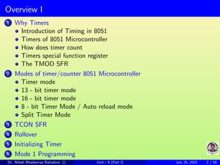
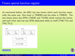
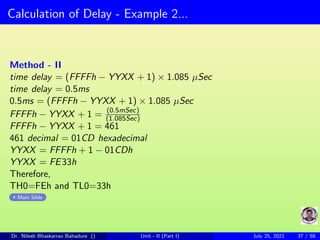
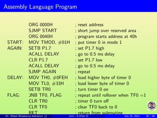
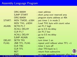
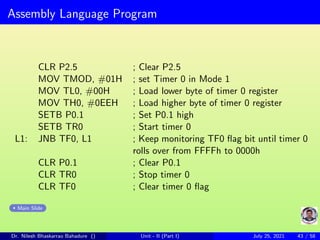
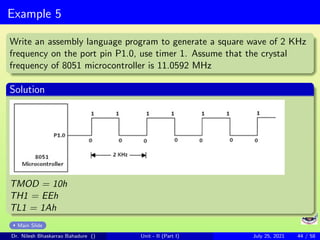
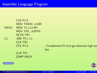
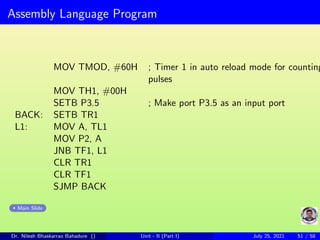
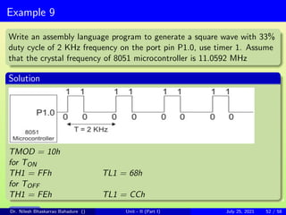
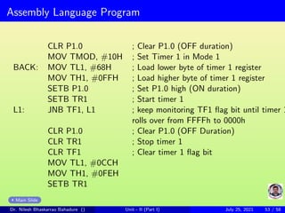
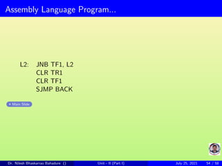
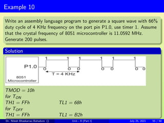
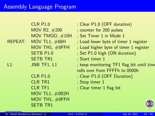
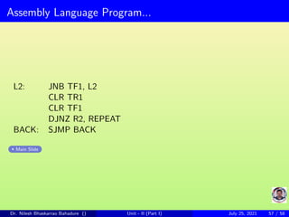
The document discusses timers in 8051 microcontrollers. It describes the different modes timers can operate in, including 13-bit, 16-bit, and 8-bit auto-reload modes. It explains the timer-related special function registers TMOD, TCON, THx and TLx. It provides steps for initializing timers, programming timers in mode 1, and calculating time delays. The document is intended to provide an understanding of how to generate time delays, measure time, and count pulses using the timers in 8051 microcontrollers.
Sheet Pile Wall Design and Construction: A Practical Guide for Civil Engineer...
Timers and counters of microcontroller 8051
1. Timers/Counters of 8051 Microcontroller
Dr. Nilesh Bhaskarrao Bahadure
https://www.sites.google.com/site/nileshbbahadure/home
July 25, 2021
Dr. Nilesh Bhaskarrao Bahadure () Unit - II (Part I) July 25, 2021 1 / 58
2. Overview I
1 Why Timers
Introduction of Timing in 8051
Timers of 8051 Microcontroller
How does timer count
Timers special function register
The TMOD SFR
2 Modes of timer/counter 8051 Microcontroller
Timer mode
13 - bit timer mode
16 - bit timer mode
8 - bit Timer Mode / Auto reload mode
Split Timer Mode
3 TCON SFR
4 Rollover
5 Initializing Timer
6 Mode 1 Programming
Dr. Nilesh Bhaskarrao Bahadure () Unit - II (Part I) July 25, 2021 2 / 58
3. Overview II
Steps to Programming Timer in Mode 1
Delay Calculation in Mode 1
7 Mode 2 Programming
Steps to Programming Timer in Mode 2
Delay Calculation in Mode 2
8 Examples
Example 1
Example 2
Example 3
Example 4
Example 5
Example 6
Example 7
Example 8
Example 9
Example 10
Dr. Nilesh Bhaskarrao Bahadure () Unit - II (Part I) July 25, 2021 3 / 58
4. Introduction to timers
Sometimes it is required to interface slower devices or peripherals with the
Microcontroller so in order to communicate properly with them, delay must
be introduced during the data transferring.
We already seen that delay is generated using assembly programming but
it is not so accurate, in some cases delay is plays a very important role and
it must be highly accurate as possible. Time delay generated by using the
internal timing facility of the Microcontroller is very close to requirement and
highly accurate. This chapter deals with time delay generation, counting
of pulses from the external device and of course generation of the pulses.
At the end of this chapter readers getting the valuable insight that how to
generate delay, time measurement, counting of pulses etc.
Main Slide
Dr. Nilesh Bhaskarrao Bahadure () Unit - II (Part I) July 25, 2021 4 / 58
5. Introduction of Timing in 8051
Micro-controllers (and many other electrical systems) use crystals to syn-
chronize operations. The 8051 uses the crystal for precisely that to syn-
chronize its operation. Effectively, the 8051 operates using what are called
“machine cycles”. A single machine cycle is the minimum amount of time
in which a single 8051 instruction can be executed. Although many instruc-
tions take multiple cycles.
A cycle is, in reality, 12 pulses of the crystal. That is to say, if an instruction
takes one machine cycle to execute, it will take 12 pulses of the crystal
to execute. Since we know the crystal is pulsing 11,059,000 times per
second and that one machine cycle is 12 pulses, we can calculate how many
instruction cycles the 8051 can execute per second:
11,059,000
12 = 921, 583
This means that the 8051 can execute 921,583 single-cycle instructions per
second.
Since a large number of 8051 instructions are single-cycle instructions it is
often considered that the 8051 can execute roughly 1 million instructions
per second.
Dr. Nilesh Bhaskarrao Bahadure () Unit - II (Part I) July 25, 2021 5 / 58
6. Timers of 8051 Microcontroller
The 8051 comes equipped with two timers, both of which may be
controlled, set, read, and configured individually. The 8051 timers have
three general functions:
1. Keeping time and/or calculating the amount of time between events,
2. Counting the events themselves (act as a counter)
3. Generating baud rates for the serial port.
The three timer uses are distinct so we will talk about each of them
separately. The first two uses will be discussed in this chapter while the
use of timers for baud rate generation will be discussed in the chapter
relating to serial ports.
Main Slide
Dr. Nilesh Bhaskarrao Bahadure () Unit - II (Part I) July 25, 2021 6 / 58
7. How does timer count
How does a timer count? The answer to this question is very simple: A
timer always counts up. It doesnt matter whether the timer is being used as
a timer, a counter, or a baud rate generator: A timer is always incremented
by the Microcontroller.
Main Slide
Dr. Nilesh Bhaskarrao Bahadure () Unit - II (Part I) July 25, 2021 7 / 58
8. Timers special function register
As mentioned before, the 8051 has two timers which each function essen-
tially the same way. One timer is TIMER0 and the other is TIMER1. The
two timers share two SFRs (TMOD and TCON) which control the timers,
and each timer also has two SFRs dedicated solely to itself (TH0/TL0 and
TH1/TL1).
Main Slide
Dr. Nilesh Bhaskarrao Bahadure () Unit - II (Part I) July 25, 2021 8 / 58
9. Timers special function register...
SFR name Description SFR address
TL0 Timer 0 lower byte 8Ah
TH0 Timer 0 higher byte 8Ch
TL1 Timer 1 lower byte 8Bh
TH1 Timer 1 higher byte 8Dh
TCON Timer control register 88h
TMOD Timer mode register 89h
Table : SFR and their addresses
Main Slide
Dr. Nilesh Bhaskarrao Bahadure () Unit - II (Part I) July 25, 2021 9 / 58
10. The TMOD SFR
TMOD (Timer Mode). The TMOD SFR is used to control the mode of
operation of both timers. Each bit of the SFR gives the microcontroller
specific information concerning how to run a timer. The high four bits (bits
4 through 7) relate to Timer 1 whereas the low four bits (bits 0 through 3)
perform the exact same functions, but for timer 0. The format of TMOD
register and working of individual bits of TMOD is shown below:
Main Slide
Dr. Nilesh Bhaskarrao Bahadure () Unit - II (Part I) July 25, 2021 10 / 58
11. Timer mode
Mode0: 13 - bit timer mode
Mode1: 16 - bit timer mode
Mode2: 8 - bit auto reload mode
Mode3: Split timer mode
Main Slide
Dr. Nilesh Bhaskarrao Bahadure () Unit - II (Part I) July 25, 2021 11 / 58
12. 13 - bit timer mode
Timer mode “0” is a 13-bit timer. This is a relic that was kept around in
the 8051 to maintain compatibility with its predecessor, the 8048. Generally
the 13-bit timer mode is not used in new development. When the timer is
in 13-bit mode, TLx will count from 0 to 31. When TLx is incremented
from 31, it will “reset” to 0 and increment THx. Thus, effectively, only 13
bits of the two timer bytes are being used: bits 0-4 of TLx and bits 0-7 of
THx. This also means, in essence, the timer can only contain 8192 values.
If you set a 13-bit timer to 0, it will overflow back to zero 8192 machine
cycles later.
Main Slide
Dr. Nilesh Bhaskarrao Bahadure () Unit - II (Part I) July 25, 2021 12 / 58
13. 16 - bit timer mode
Timer mode “1” is a 16-bit timer. This is a very commonly used mode. It
functions just like 13-bit mode except that all 16 bits are used.
TLx is incremented from 0 to 255. When TLx is subsequently incremented
from 255, it resets to 0 and causes THx to be incremented by 1. Since this
is a full 16- bit timer, the timer may contain up to 65536 distinct values. If
you set a 16-bit timer to 0, it will overflow back to 0 after 65,536 machine
cycles.
Main Slide
Dr. Nilesh Bhaskarrao Bahadure () Unit - II (Part I) July 25, 2021 13 / 58
14. 16 - bit timer mode...
Main Slide
Dr. Nilesh Bhaskarrao Bahadure () Unit - II (Part I) July 25, 2021 14 / 58
15. 8 - bit Timer Mode / Auto reload mode
The instruction MOV TMOD, #02h / MOV 89h, #02h would put timer 0
into auto reload mode i.e. mode 2 defining 8 - bit timer using TL0 as the
working register and TH0 as the automatic reload register.
In mode 2, the working register is only 8 - bit wide and so the base number
is 8 bit wide. When the TLx register rolls over it is automatically reloaded
with the contents of the THx register, whose contents remain the same, so
the base number goes into the THx register.
Main Slide
Dr. Nilesh Bhaskarrao Bahadure () Unit - II (Part I) July 25, 2021 15 / 58
16. 8 - bit Timer Mode / Auto reload mode...
Main Slide
Dr. Nilesh Bhaskarrao Bahadure () Unit - II (Part I) July 25, 2021 16 / 58
17. 8 - bit Timer Mode / Auto reload mode...
Timer mode “2” is an 8-bit auto-reload mode. When a timer is in mode 2,
THx holds the ”reload value” and TLx is the timer itself. Thus, TLx starts
counting up. When TLx reaches 255 and is subsequently incremented,
instead of resetting to 0 (as in the case of modes 0 and 1), it will be reset
to the value stored in THx. For example, lets say TH0 holds the value FDh
and TL0 holds the value FEh. If we were to watch the values of TH0 and
TL0 for a few machine cycles this is what we had see:
Main Slide
Dr. Nilesh Bhaskarrao Bahadure () Unit - II (Part I) July 25, 2021 17 / 58
18. 8 - bit Timer Mode / Auto reload mode...
Machine cycle TH0 value TL0 value
1 FDh FEh
2 FDh FFh
3 FDh FDh
4 FDh FEh
5 FDh FFh
6 FDh FDh
7 FDh FEh
Main Slide
Dr. Nilesh Bhaskarrao Bahadure () Unit - II (Part I) July 25, 2021 18 / 58
19. Mode 3: Split Timer Mode
Timer mode “3” is a split-timer mode. When Timer 0 is placed in mode 3,
it essentially becomes two separate 8-bit timers. That is to say, Timer 0 is
TL0 and Timer 1 is TH0. Both timers count from 0 to 255 and overflow
back to 0. All the bits that are related to Timer 1 will now be tied to TH0.
While Timer 0 is in split mode, the real Timer 1 (i.e. TH1 and TL1) can
be put into modes 0, 1 or 2 normally–however, you may not start or stop
the real timer 1 since the bits that do that are now linked to TH0. The real
timer 1, in this case, will be incremented every machine cycle no matter
what. The only real use I can see of using split timer mode is if you need
to have two separate timers and, additionally, a baud rate generator. In
such case you can use the real Timer 1 as a baud rate generator and use
TH0/TL0 as two separate timers.
Main Slide
Dr. Nilesh Bhaskarrao Bahadure () Unit - II (Part I) July 25, 2021 19 / 58
20. TCON SFR
D7 D6 D5 D4 D3 D2 D1 D0
TF1 TR1 TF0 TR0 IE1 IT1 IE0 IT0
Main Slide
Dr. Nilesh Bhaskarrao Bahadure () Unit - II (Part I) July 25, 2021 20 / 58
21. Rollover
The timer clock increments in timer clock cycles from the base number up
to the maximum value of the 16 - bit register, which is FFFFh. One more
increment would cause the register to rollover to 0000h and set the timer
flag (TF) to 1. The TF is a bit in the TCON register SFR.
On power - up the default values of all the TCON register are zero and so
the timer flags TF1 and TF0 are zero; the control action of timer 0 is the
same using TR0. Timer 1 is turned on by making TR1 =1 and it is turned
off by making TR1 = 0
Main Slide
Dr. Nilesh Bhaskarrao Bahadure () Unit - II (Part I) July 25, 2021 21 / 58
22. Rollover...
As soon as TR0 = 1, the timer 0 register TH0 - TL0 starts incrementing
upwards from their base number. Upon rollover the TF0 flag sets to 1
and this indicates that the delay has been completed. A possible assembly
language routine for the 0.5 ms delay could be:
DELAY: MOV TH0, #0FEH ; Load timer 0 higher byte with FEh
MOV TL0, #33H ; Load timer 0 lower byte with 33h
SETB TR0 ; Turn timer 0 on
FLAG: JNB TF0, FLAG ; Jump to FLAG if TF0 is not bit (not equ
CLR TR0 ; Turn timer 0 off
CLR TF0 ; Clear TF0 to zero
RET ; Return from subroutine
Main Slide
Dr. Nilesh Bhaskarrao Bahadure () Unit - II (Part I) July 25, 2021 22 / 58
23. Initializing Timer
Now that we’ve discussed the timer related SFRs we are ready to write code
that will initialize the timer and start it running. As you’ll recall, we first
must decide what mode we want the timer to be in. In this case we want
a 16-bit timer that runs continuously; that is to say, it is not dependent
on any external pins. We must first initialize the TMOD SFR. Since we
are working with timer 0 we will be using the lowest 4 bits of TMOD. The
first two bits, GATE0 and C/T̄ are both 0 since we want the timer to be
independent of the external pins. 16-bit mode is timer mode 1 so we must
clear T0M1 and set T0M0. Effectively, the only bit we want to turn on is
bit 0 of TMOD. Thus to initialize the timer we execute the instruction:
MOV TMOD, #01h
Timer 0 is now in 16-bit timer mode. However, the timer is not running.
To start the timer running we must set the TR0 bit We can do that by
executing the instruction:
SETB TR0
Upon executing these two instructions timer 0 will immediately begin count-
ing, being incremented once every machine cycle (every 12 crystal pulses).
Dr. Nilesh Bhaskarrao Bahadure () Unit - II (Part I) July 25, 2021 23 / 58
24. Steps to Programming Timer in Mode 1
To generate a time delay or waveforms, using the timers in mode 1 the
following steps are taken
1. Load TMOD register with the value indicating which timer (timer 0 or
timer 1) is to be used and timer mode is selected.
2. Load timer register TLx and THx with the initial count values, according
to the time delay value calculated.
3. Start the timer; this may be done either by software control or by hardware
control.
4. Keep monitoring the timer flag (TFx) with the instruction JNB TFx,
TARGET to see and confirm whether timer flag bit is raised or not. Get
out of the loop when timer flag bit TFx becomes high. When TFx is raised
indicating the amount of delay is calculated so need to stop the timer.
Main Slide
Dr. Nilesh Bhaskarrao Bahadure () Unit - II (Part I) July 25, 2021 24 / 58
25. Steps to Programming Timer in Mode 1...
5. Stop the timer. When timer flag bit TFx is raised to high indicating that
timer is reached to their maximum limit and overflow back to 0000h and
hence to stop the timer.
6. Clear the timer flag bit TFx for the next round, in other words to repeat
the process timer flag bit TFx must be cleared. If TFx is not cleared then
even if the timer is started for the next round, it is not possible to sense
whether the timer is calculated the desired delay or not.
7. Go back to step 2 to load the values of timer register TLx and THx
again.
Main Slide
Dr. Nilesh Bhaskarrao Bahadure () Unit - II (Part I) July 25, 2021 25 / 58
26. Delay Calculation ib Mode 1
To calculate exact time delay and square wave frequency generation we
need to know the crystal frequency. Assume that the 8051 microcontroller’s
crystal frequency is 11.0592 MHz, and then delay calculation in Hexadecimal
and Decimal is as follows:
In Hexadecimal
Time Delay = (FFFFh − YYXX + 1) × 1.085 µs
Where YYXX are initial count values to be loaded in THx and TLx respec-
tively. Values of YYXX are in Hexadecimal format.
In Decimal
Time Delay = (65535 − NNNNN + 1) × 1.085 µs
or
Time Delay = (65536 − NNNNN) × 1.085 µs
Where NNNNN indicates initial count value to be loaded in the timer reg-
ister TLx and THx respectively.
Main Slide
Dr. Nilesh Bhaskarrao Bahadure () Unit - II (Part I) July 25, 2021 26 / 58
27. Steps to Programming Timer in Mode 2
To generate a time delay or waveform using timers mode 2 take the following
steps.
1. Load TMOD register with the value indicating which timer, timer 0 or
timer 1 is to be used and select the timer mode.
2. Load the THx register with initial count value, according to the delay
value calculated.
3. Start the timer; this may be done either by using software control or by
hardware control. The timer of 8051 microcontroller is supported both.
4. Keep monitoring the timer flag (TFx) with the instruction “JNB TFx,
TARGET” to see and confirm whether timer flag bit is raised or not. Get
out of the loop when timer flag bit TFx becomes high.
Main Slide
Dr. Nilesh Bhaskarrao Bahadure () Unit - II (Part I) July 25, 2021 27 / 58
28. Steps to Programming Timer in Mode 2...
5. Clear the timer flag bit TFx for the next round, in other words to repeat
the process timer flag bit TFx must be cleared. If TFx is not cleared then
even if the timer is started for the next round, it is not possible to sense
whether the timer is calculated the desired delay or not.
6. Go back to step 4, since mode 2 is auto reload mode, therefore no need
to load the timer register THx again. if go back to step 3 and start the
timer again then there is no issue, it will also produced the same result, but
as we are not stopping the timer in step 5, it is advisable that to stop the
timer first and then its okay to go back to step 3.
Main Slide
Dr. Nilesh Bhaskarrao Bahadure () Unit - II (Part I) July 25, 2021 28 / 58
29. Delay Calculation in Mode 2
To calculate exact time delay and square wave frequency generation we
need to know the crystal frequency. Assume that the 8051 microcontrollers
crystal frequency is 11.0592 MHz, and then delay calculation in Hexadecimal
and Decimal is as follows:
In Hexadecimal
Time Delay = (FFh − YY + 1) × 1.085 µs
Where YY are initial count values to be loaded in THx. Values of YY are
in Hexadecimal format.
In Decimal
Time Delay = (255 − NNN + 1) × 1.085 µs
or
Time Delay = (256 − NNN) × 1.085 µs
Where NNN indicates initial count value to be loaded in the timer register
THx .
Main Slide
Dr. Nilesh Bhaskarrao Bahadure () Unit - II (Part I) July 25, 2021 29 / 58
30. Example 1
A 1 KHz square wave signal is to be generated from port pin P1.7. The
microcontroller clock frequency is 11.0592 MHz
(a) Determine the required time delay
(b) Using timer 0 determine the base number that must go into the TH0
and TL0 registers.
Solution:
Main Slide
Dr. Nilesh Bhaskarrao Bahadure () Unit - II (Part I) July 25, 2021 30 / 58
31. Example 1...
(a) One cycle time T of the required - square wave signal equals 1/frequency
T = 1
f = 1
1000 = 1ms
For the square wave TON = TOFF
Therefore,
DelayTime = T
2 = 1ms
2 = 0.5ms
(b) Timer clock = Microclock / 12
timer clock=(11.0592 MHz)/12=921.6 KHz
timer cycle time=1/f=1/(921.6 KHz)=1.085 µs
Main Slide
Dr. Nilesh Bhaskarrao Bahadure () Unit - II (Part I) July 25, 2021 31 / 58
32. Calculation of Delay - Example 1...
Method - I
Delay count = (Delay time)
(Timer cycle time)
Delay count = (0.5ms)
(1.085µs) = 461 (Nearest whole number)
Base number = 65536 − delay count
Base number = 65536 − 461 = 65075
65075 Decimal = FE33h Hexadecimal
Therefore
TH0=FEh and TL0=33h
Main Slide
Dr. Nilesh Bhaskarrao Bahadure () Unit - II (Part I) July 25, 2021 32 / 58
33. Calculation of Delay - Example 1...
Method - II
time delay = (FFFFh − YYXX + 1) × 1.085 µSec
time delay = 0.5ms
0.5ms = (FFFFh − YYXX + 1) × 1.085 µSec
FFFFh − YYXX + 1 = (0.5mSec)
(1.085Sec)
FFFFh − YYXX + 1 = 461
461 decimal = 01CD hexadecimal
YYXX = FFFFh + 1 − 01CDh
YYXX = FE33h
Therefore,
TH0=FEh and TL0=33h
Main Slide
Dr. Nilesh Bhaskarrao Bahadure () Unit - II (Part I) July 25, 2021 33 / 58
34. Example 2
A 8051 Microcontroller having an 11.0592 MHz clock is to be used to
generate a 1 kHz square - wave signal from pin 7 of port 1. Write a suitable
assembly program to achieve this.
Solution:
Main Slide
Dr. Nilesh Bhaskarrao Bahadure () Unit - II (Part I) July 25, 2021 34 / 58
35. Example 2...
(a) One cycle time T of the required - square wave signal equals 1/frequency
T = 1
f = 1
1000 = 1ms
For the square wave TON = TOFF
Therefore,
DelayTime = T
2 = 1ms
2 = 0.5ms
(b) Timer clock = Microclock / 12
timer clock=(11.0592 MHz)/12=921.6 KHz
timer cycle time=1/f=1/(921.6 KHz)=1.085 µs
Main Slide
Dr. Nilesh Bhaskarrao Bahadure () Unit - II (Part I) July 25, 2021 35 / 58
36. Calculation of Delay - Example 2...
Method - I
Delay count = (Delay time)
(Timer cycle time)
Delay count = (0.5ms)
(1.085µs) = 461 (Nearest whole number)
Base number = 65536 − delay count
Base number = 65536 − 461 = 65075
65075 Decimal = FE33h Hexadecimal
Therefore
TH0=FEh and TL0=33h
Main Slide
Dr. Nilesh Bhaskarrao Bahadure () Unit - II (Part I) July 25, 2021 36 / 58
37. Calculation of Delay - Example 2...
Method - II
time delay = (FFFFh − YYXX + 1) × 1.085 µSec
time delay = 0.5ms
0.5ms = (FFFFh − YYXX + 1) × 1.085 µSec
FFFFh − YYXX + 1 = (0.5mSec)
(1.085Sec)
FFFFh − YYXX + 1 = 461
461 decimal = 01CD hexadecimal
YYXX = FFFFh + 1 − 01CDh
YYXX = FE33h
Therefore,
TH0=FEh and TL0=33h
Main Slide
Dr. Nilesh Bhaskarrao Bahadure () Unit - II (Part I) July 25, 2021 37 / 58
38. Assembly Language Program
ORG 0000H ; reset address
SJMP START ; short jump over reserved area
ORG 0040H ; program starts address at 40h
START: MOV TMOD, #01H ; put timer 0 in mode 1
AGAIN: SETB P1.7 ; set P1.7 high
ACALL DELAY ; go to 0.5 ms delay
CLR P1.7 ; set P1.7 low
ACALL DELAY ; go to 0.5 ms delay
SJMP AGAIN ; repeat
DELAY: MOV TH0, #0FEH ; load higher byte of timer 0
MOV TL0, #33H ; load lower byte of timer 0
SETB TR0 ; turn timer 0 on
FLAG: JNB TF0, FLAG ; repeat until rollover when TF0 =1
CLR TR0 ; timer 0 turn off
CLR TF0 ; clear TF0 back to 0
RET ; return from subroutine
Dr. Nilesh Bhaskarrao Bahadure () Unit - II (Part I) July 25, 2021 38 / 58
39. Example 3
A 8051 Microcontroller having an 11.0592 MHz clock is to be used to
generate a 4 kHz square - wave signal from pin 7 of port 1. Write a suitable
assembly program to achieve this. Use timer 1 in auto - reload mode.
Solution:
Main Slide
Dr. Nilesh Bhaskarrao Bahadure () Unit - II (Part I) July 25, 2021 39 / 58
40. Example 3...
Square - wave cycle time = 1/4KHz=1/4000=0.25 mSec
Delay required for a square - wave = Half the cycle time (ON Time = OFF
Time) = 0.125 ms = 125 µs
In mode 2, count value is calculated as
Delaycount = (256 − NNN) × 1.085 µs
Where NNN is the count value
125 µs = (256 − NNN) × 1.085 µs
256 − NNN = (125 µs)
(1.085 µs) = 115
NNN = 256 − 115 = 141
141 Decimal = 8Dh Hexadecimal
Main Slide
Dr. Nilesh Bhaskarrao Bahadure () Unit - II (Part I) July 25, 2021 40 / 58
41. Assembly Language Program
ORG 0000H ; reset address
SJMP START ; short jump over reserved area
ORG 0040H ; program starts address at 40h
START: MOV TMOD, #20H ; put timer 1 in mode 2
MOV TH1, #8DH ; Load TH1 byte with count value
AGAIN: SETB P1.7 ; set P1.7 high
ACALL DELAY ; go to 0.5 ms delay
CLR P1.7 ; set P1.7 low
ACALL DELAY ; go to 0.5 ms delay
SJMP AGAIN ; repeat
DELAY: SETB TR1 ; turn timer 1 on
FLAG: JNB TF1, FLAG ; repeat until rollover when TF1 =1
CLR TR1 ; timer 1 turn off
CLR TF1 ; clear TF0 back to 1
RET ; return from subroutine
END ; no more assembly language after here
Dr. Nilesh Bhaskarrao Bahadure () Unit - II (Part I) July 25, 2021 41 / 58
42. Example 4
Write an assembly language program to generate pulse width of 5 ms on
port pin P0.1 using timer 0. Assume that the crystal frequency of 8051
microcontroller is 11.0592 MHz
Solution
TMOD = 01h
TH0 = EEh
TL0 = 00h
Main Slide
Dr. Nilesh Bhaskarrao Bahadure () Unit - II (Part I) July 25, 2021 42 / 58
43. Assembly Language Program
CLR P2.5 ; Clear P2.5
MOV TMOD, #01H ; set Timer 0 in Mode 1
MOV TL0, #00H ; Load lower byte of timer 0 register
MOV TH0, #0EEH ; Load higher byte of timer 0 register
SETB P0.1 ; Set P0.1 high
SETB TR0 ; Start timer 0
L1: JNB TF0, L1 ; Keep monitoring TF0 flag bit until timer 0
rolls over from FFFFh to 0000h
CLR P0.1 ; Clear P0.1
CLR TR0 ; Stop timer 0
CLR TF0 ; Clear timer 0 flag
Main Slide
Dr. Nilesh Bhaskarrao Bahadure () Unit - II (Part I) July 25, 2021 43 / 58
44. Example 5
Write an assembly language program to generate a square wave of 2 KHz
frequency on the port pin P1.0, use timer 1. Assume that the crystal
frequency of 8051 microcontroller is 11.0592 MHz
Solution
TMOD = 10h
TH1 = EEh
TL1 = 1Ah
Main Slide
Dr. Nilesh Bhaskarrao Bahadure () Unit - II (Part I) July 25, 2021 44 / 58
45. Assembly Language Program
CLR P1.0
MOV TMOD, #10H
BACK: MOV TL1,#1AH
MOV TH1, #0FFH
SETB TR1
L1: JNB TF1, L1
CLR TR1
CPL P1.0 ; Complement P1.0 to get alternate high and
low
CLR TF1
SJMP BACK
Main Slide
Dr. Nilesh Bhaskarrao Bahadure () Unit - II (Part I) July 25, 2021 45 / 58
46. Example 6
Write an assembly language program to generate a square wave of 100 Hz
frequency on the port pin P1.1, use timer 1. Assume that the crystal
frequency of 8051 microcontroller is 11.0592 MHz
Solution
TMOD = 10h
TH1 = EEh
TL1 = 00h
Main Slide
Dr. Nilesh Bhaskarrao Bahadure () Unit - II (Part I) July 25, 2021 46 / 58
47. Assembly Language Program
CLR P1.0
MOV TMOD, #10H
BACK: MOV TL1,#00H
MOV TH1, #0FFH
SETB TR1
L1: JNB TF1, L1
CLR TR1
CPL P1.1 ; Complement P1.1 to get alternate high and
low
CLR TF1
SJMP BACK
Main Slide
Dr. Nilesh Bhaskarrao Bahadure () Unit - II (Part I) July 25, 2021 47 / 58
48. Example 7
Write an assembly language program to generate a square wave of 1.8
KHz frequency on the port pin P1.0, use timer 1 in auto reload mode.
Assume that the crystal frequency of 8051 microcontroller is 11.0592 MHz
Solution
TMOD = 20h
TH1 = 00h
Main Slide
Dr. Nilesh Bhaskarrao Bahadure () Unit - II (Part I) July 25, 2021 48 / 58
49. Assembly Language Program
CLR P1.0
MOV TMOD, #20H ; Set timer 1 in auto reload mode (Mode
2)
MOV TH1, #00H
SETB TR1
L1: JNB TF1, L1
CPL P1.0 ; Complement P1.0 to get alternate high and
low
CLR TF1
SJMP L1
Main Slide
Dr. Nilesh Bhaskarrao Bahadure () Unit - II (Part I) July 25, 2021 49 / 58
50. Example 8
Assuming that the clock pulses are fed to the pin P3.5, write an assembly
language program for counter 1 in auto reload mode to count the pulses
and display the state of timer 1 lower byte register TL1 count on port P2.
Solution
TMOD = 60h
Main Slide
Dr. Nilesh Bhaskarrao Bahadure () Unit - II (Part I) July 25, 2021 50 / 58
51. Assembly Language Program
MOV TMOD, #60H ; Timer 1 in auto reload mode for counting
pulses
MOV TH1, #00H
SETB P3.5 ; Make port P3.5 as an input port
BACK: SETB TR1
L1: MOV A, TL1
MOV P2, A
JNB TF1, L1
CLR TR1
CLR TF1
SJMP BACK
Main Slide
Dr. Nilesh Bhaskarrao Bahadure () Unit - II (Part I) July 25, 2021 51 / 58
52. Example 9
Write an assembly language program to generate a square wave with 33%
duty cycle of 2 KHz frequency on the port pin P1.0, use timer 1. Assume
that the crystal frequency of 8051 microcontroller is 11.0592 MHz
Solution
TMOD = 10h
for TON
TH1 = FFh TL1 = 68h
for TOFF
TH1 = FEh TL1 = CCh
Main Slide
Dr. Nilesh Bhaskarrao Bahadure () Unit - II (Part I) July 25, 2021 52 / 58
53. Assembly Language Program
CLR P1.0 ; Clear P1.0 (OFF duration)
MOV TMOD, #10H ; Set Timer 1 in Mode 1
BACK: MOV TL1, #68H ; Load lower byte of timer 1 register
MOV TH1, #0FFH ; Load higher byte of timer 1 register
SETB P1.0 ; Set P1.0 high (ON duration)
SETB TR1 ; Start timer 1
L1: JNB TF1, L1 ; keep monitoring TF1 flag bit until timer 1
rolls over from FFFFh to 0000h
CLR P1.0 ; Clear P1.0 (OFF Duration)
CLR TR1 ; Stop timer 1
CLR TF1 ; Clear timer 1 flag bit
MOV TL1, #0CCH
MOV TH1, #0FEH
SETB TR1
Main Slide
Dr. Nilesh Bhaskarrao Bahadure () Unit - II (Part I) July 25, 2021 53 / 58
54. Assembly Language Program...
L2: JNB TF1, L2
CLR TR1
CLR TF1
SJMP BACK
Main Slide
Dr. Nilesh Bhaskarrao Bahadure () Unit - II (Part I) July 25, 2021 54 / 58
55. Example 10
Write an assembly language program to generate a square wave with 66%
duty cycle of 4 KHz frequency on the port pin P1.0, use timer 1. Assume
that the crystal frequency of 8051 microcontroller is 11.0592 MHz.
Generate 200 pulses.
Solution
TMOD = 10h
for TON
TH1 = FFh TL1 = 68h
for TOFF
TH1 = FFh TL1 = B2h
Dr. Nilesh Bhaskarrao Bahadure () Unit - II (Part I) July 25, 2021 55 / 58
56. Assembly Language Program
CLR P1.0 ; Clear P1.0 (OFF duration)
MOV R2, #200 ; counter for 200 pulses
MOV TMOD, #10H ; Set Timer 1 in Mode 1
REPEAT: MOV TL1, #68H ; Load lower byte of timer 1 register
MOV TH1, #0FFH ; Load higher byte of timer 1 register
SETB P1.0 ; Set P1.0 high (ON duration)
SETB TR1 ; Start timer 1
L1: JNB TF1, L1 ; keep monitoring TF1 flag bit until time
rolls over from FFFFh to 0000h
CLR P1.0 ; Clear P1.0 (OFF Duration)
CLR TR1 ; Stop timer 1
CLR TF1 ; Clear timer 1 flag bit
MOV TL1, #0B2H
MOV TH1, #0FFH
SETB TR1
Main Slide
Dr. Nilesh Bhaskarrao Bahadure () Unit - II (Part I) July 25, 2021 56 / 58
57. Assembly Language Program...
L2: JNB TF1, L2
CLR TR1
CLR TF1
DJNZ R2, REPEAT
BACK: SJMP BACK
Main Slide
Dr. Nilesh Bhaskarrao Bahadure () Unit - II (Part I) July 25, 2021 57 / 58
58. Thank you
Please send your feedback at nbahadure@gmail.com
For more details and updates kindly visit
https://sites.google.com/site/nileshbbahadure/home
Main Slide
Dr. Nilesh Bhaskarrao Bahadure () Unit - II (Part I) July 25, 2021 58 / 58