The document provides information about programmable logic controllers (PLCs):
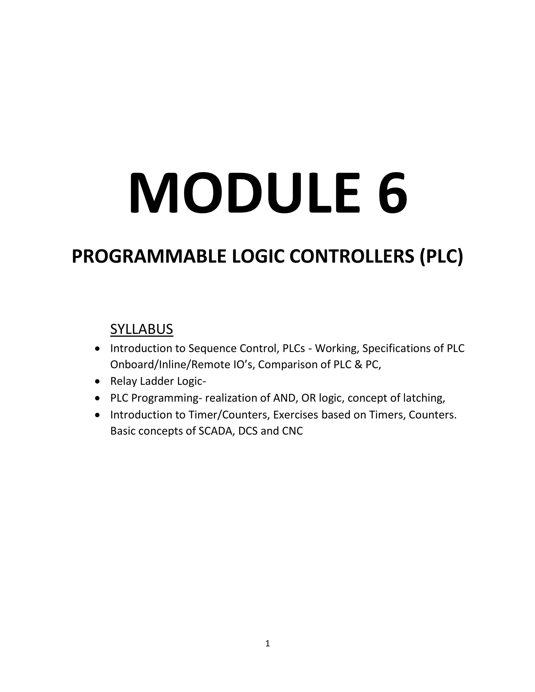
1. It introduces PLCs, describing their use in industrial processes to provide flexible, ruggedized control as an alternative to hard-wired relays. PLCs were first used in automobile manufacturing.
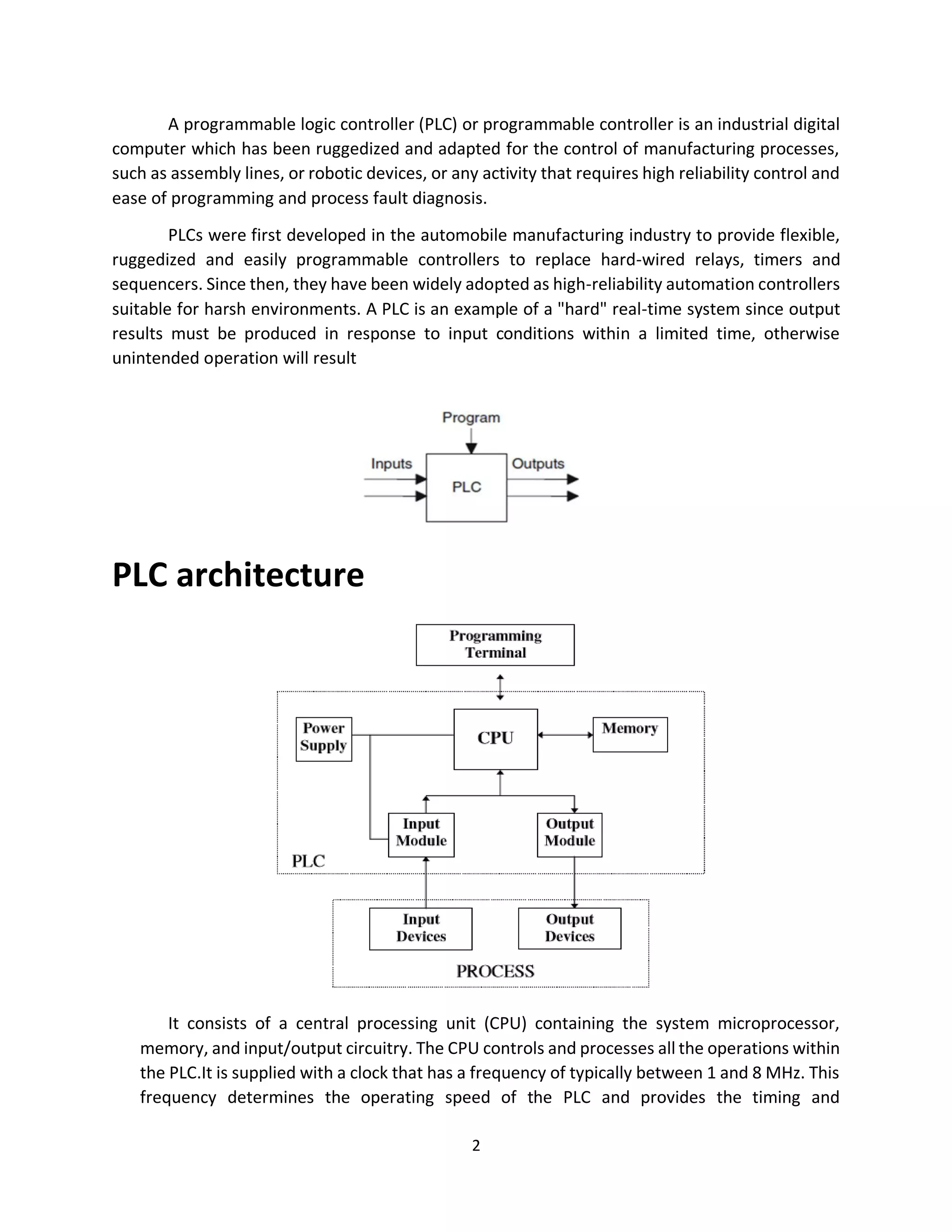
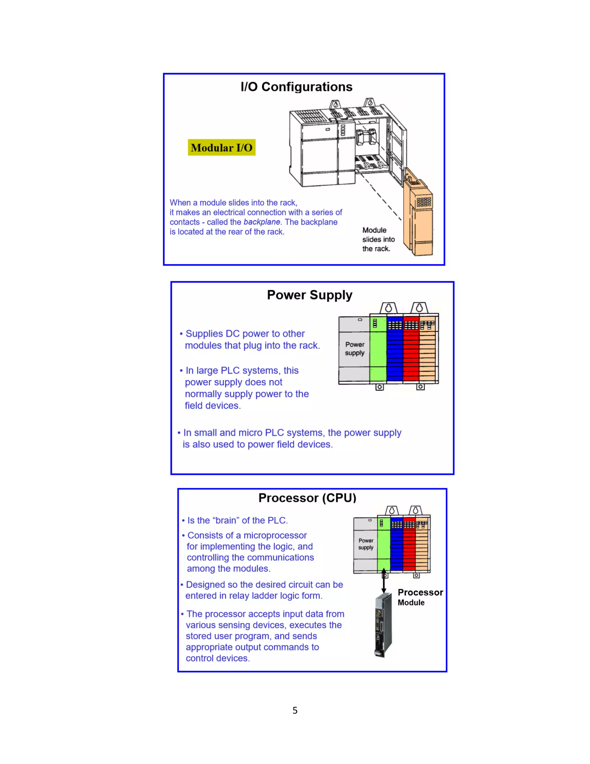
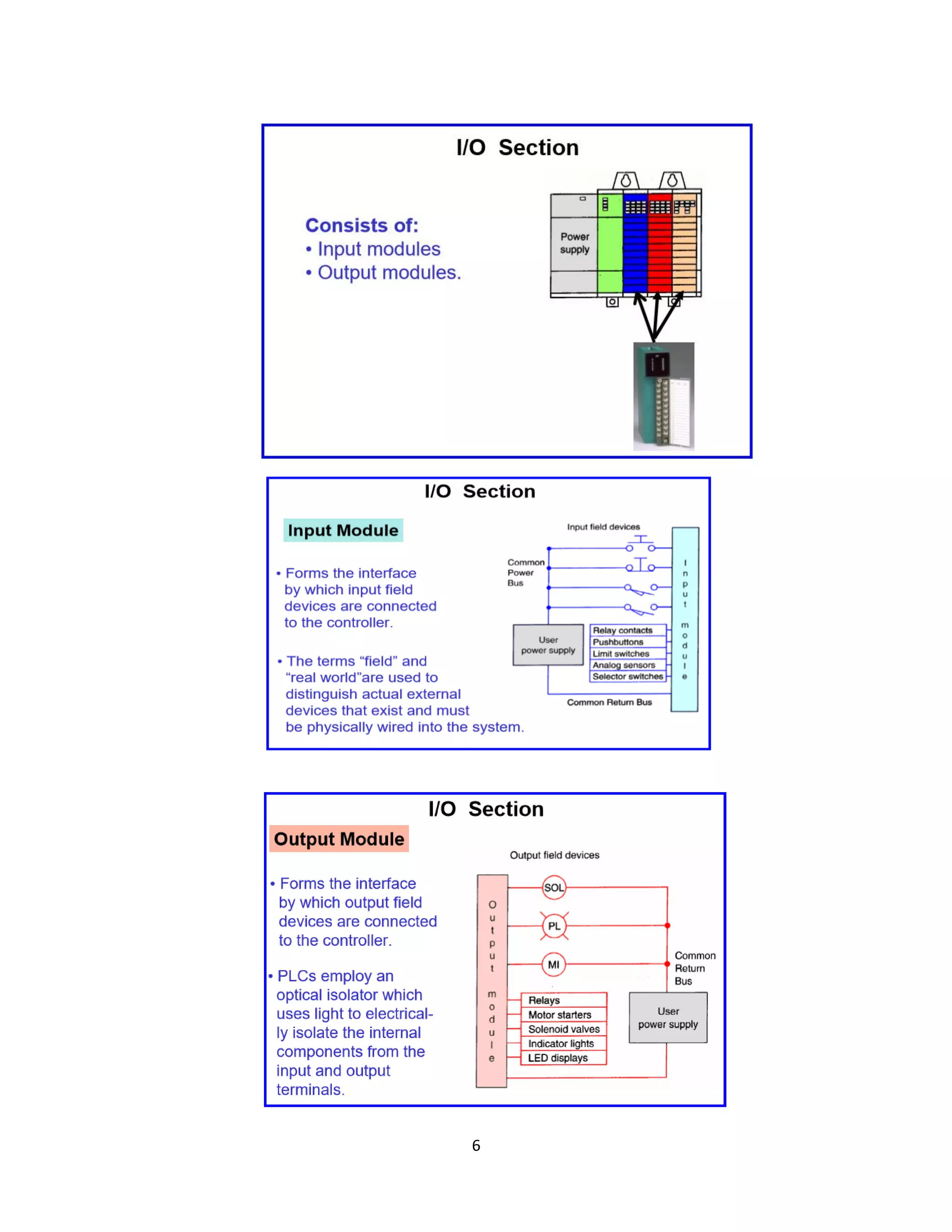
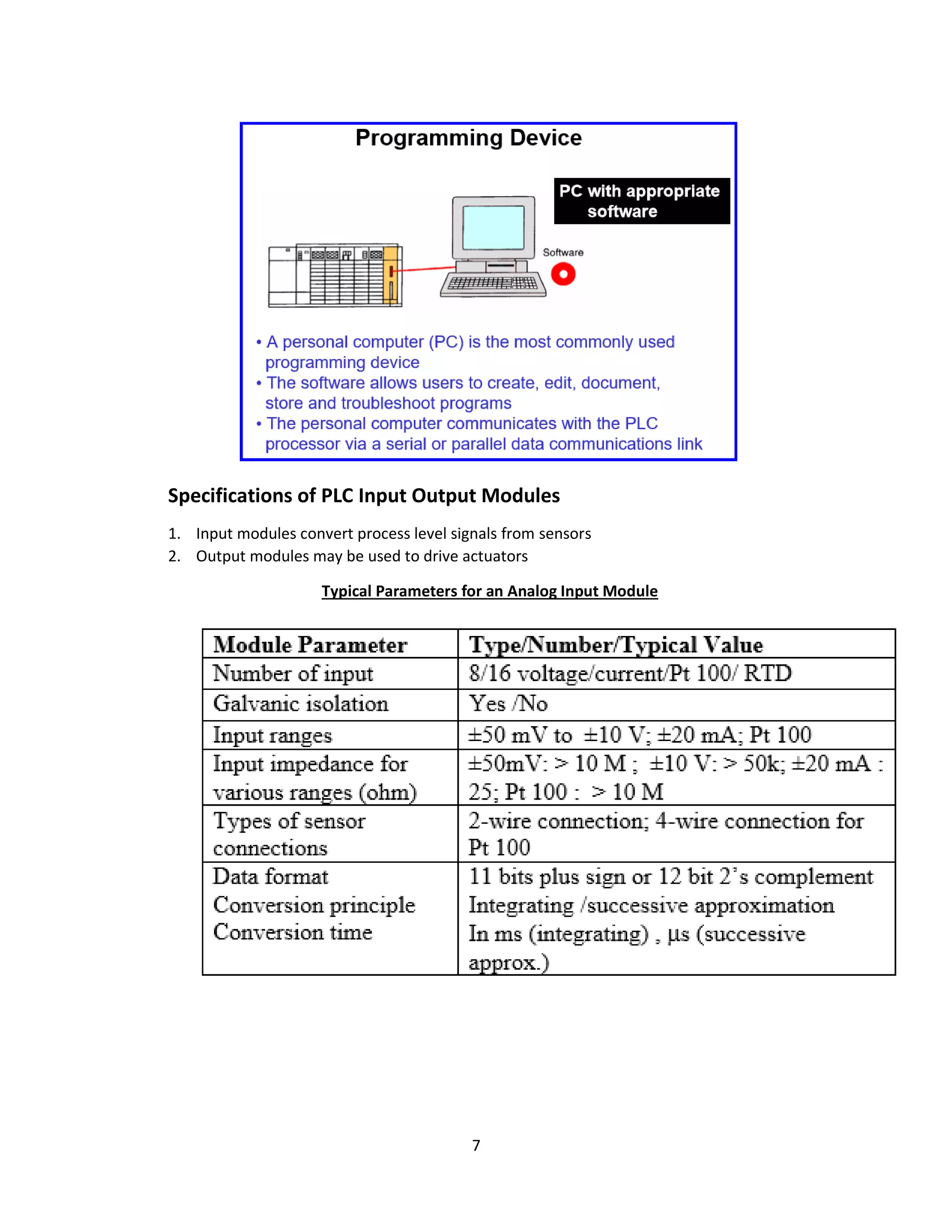
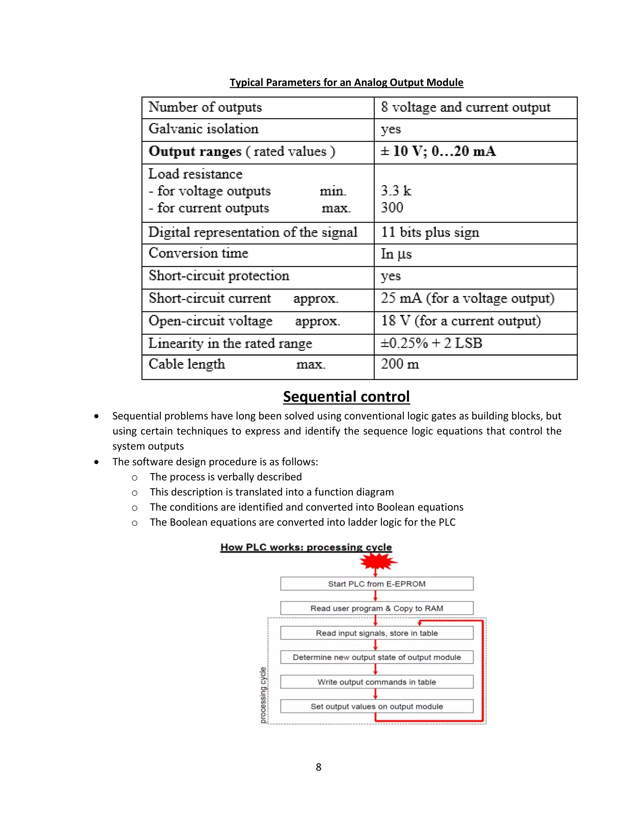
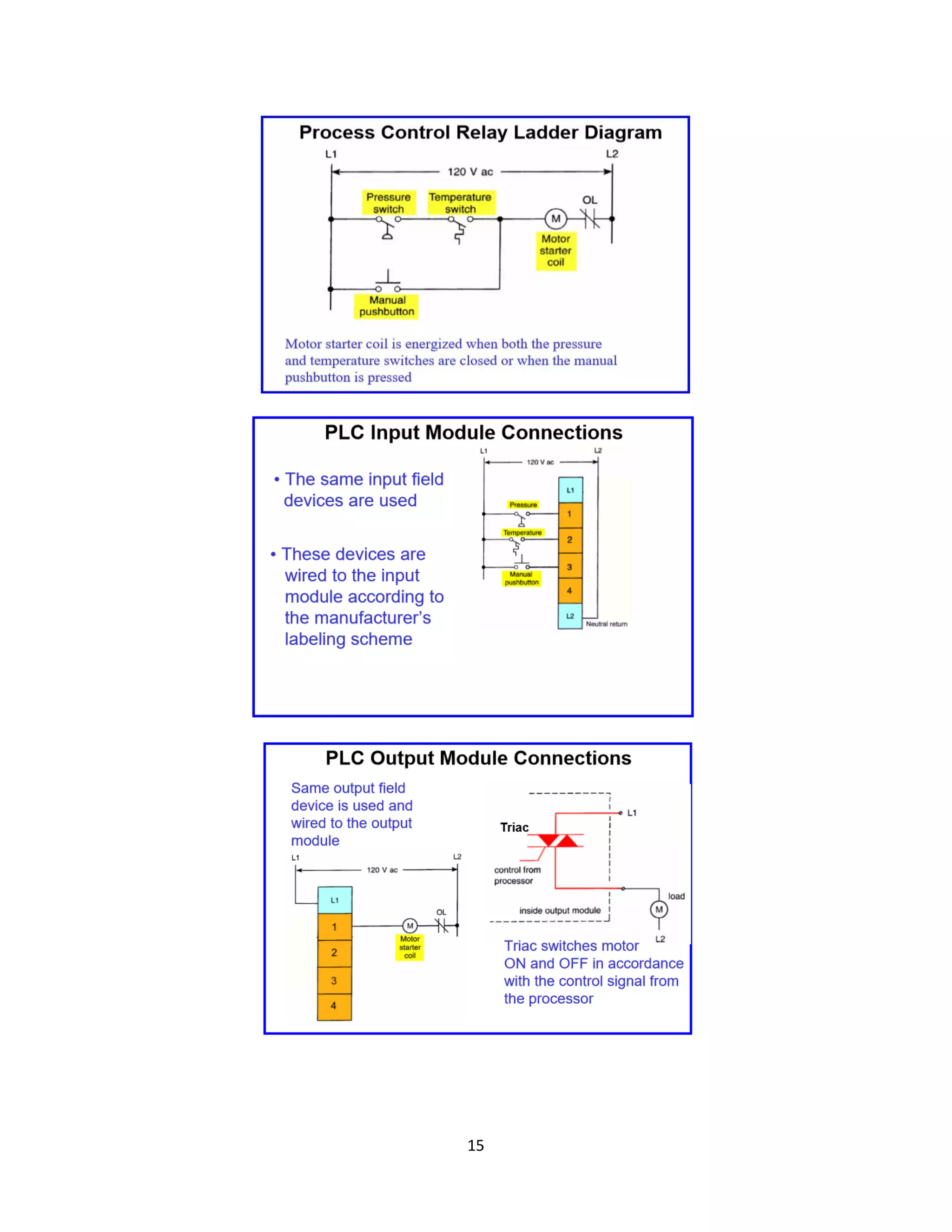
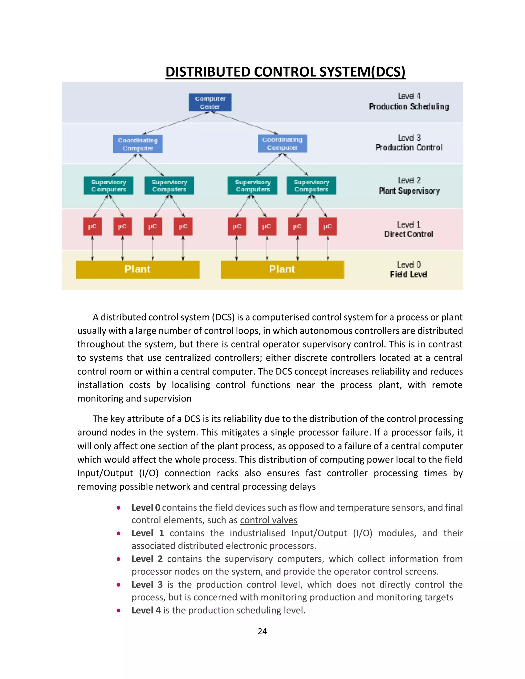
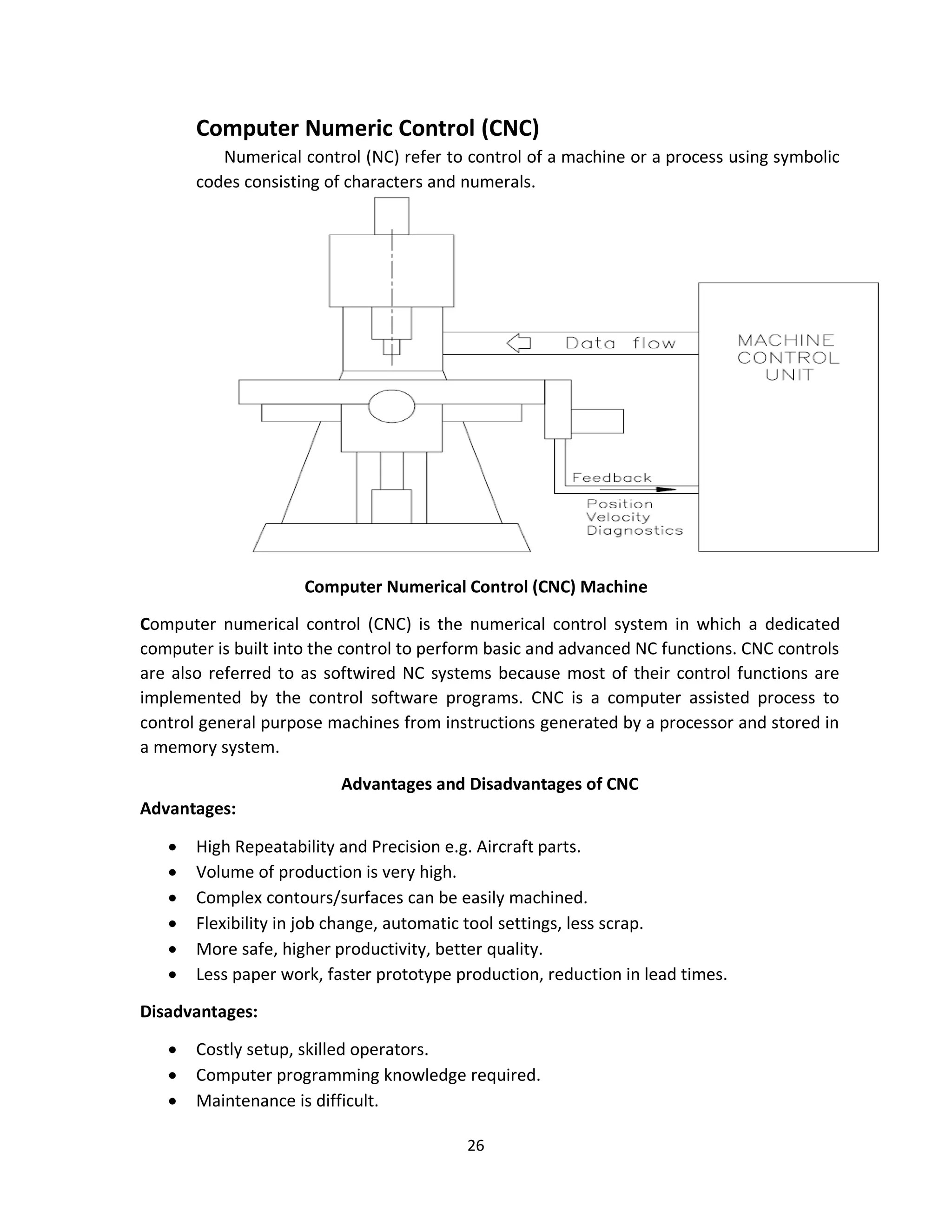
2. Details are given about PLC architecture, including the central processing unit, memory, input/output circuitry, system buses, and the continuous control loop of reading inputs, executing logic, and changing outputs.
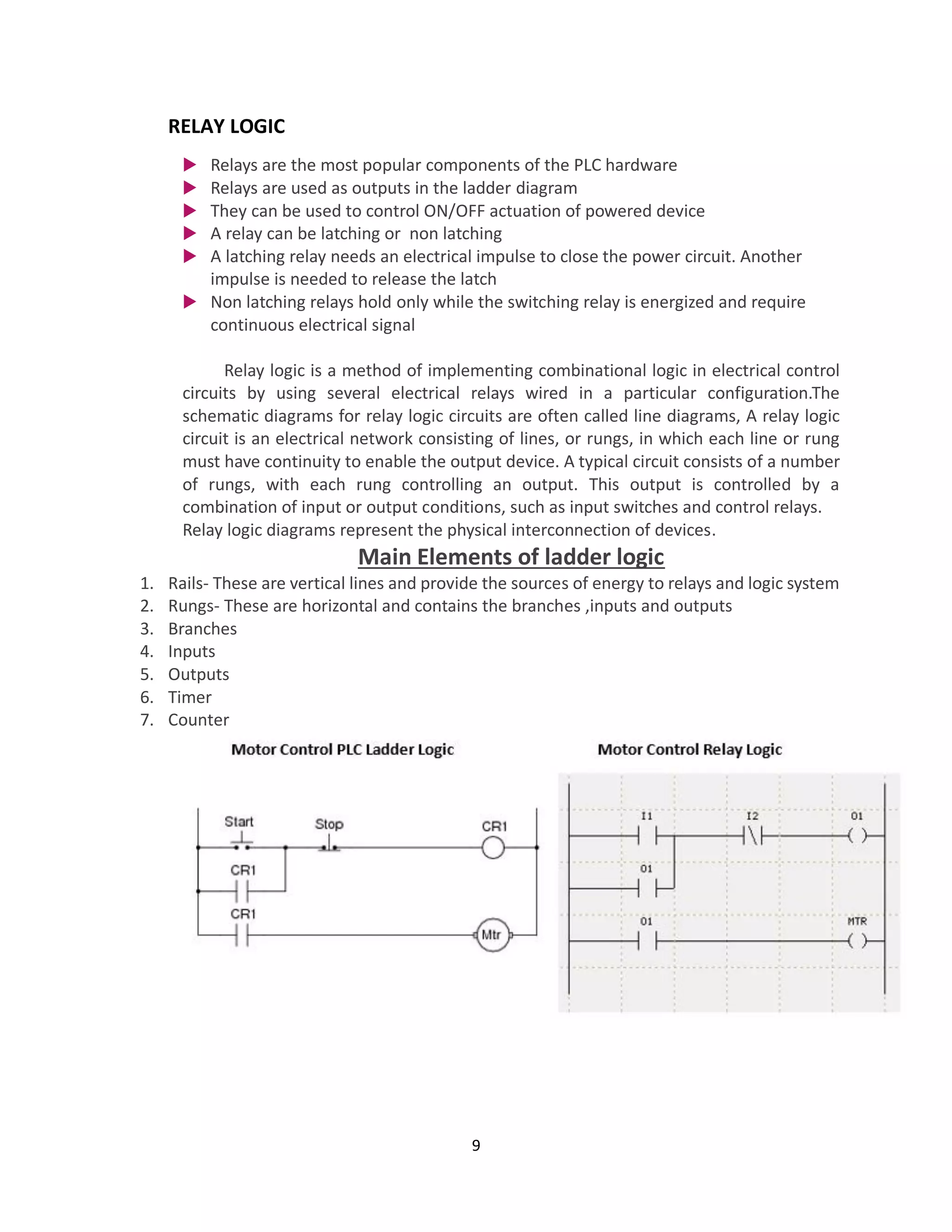
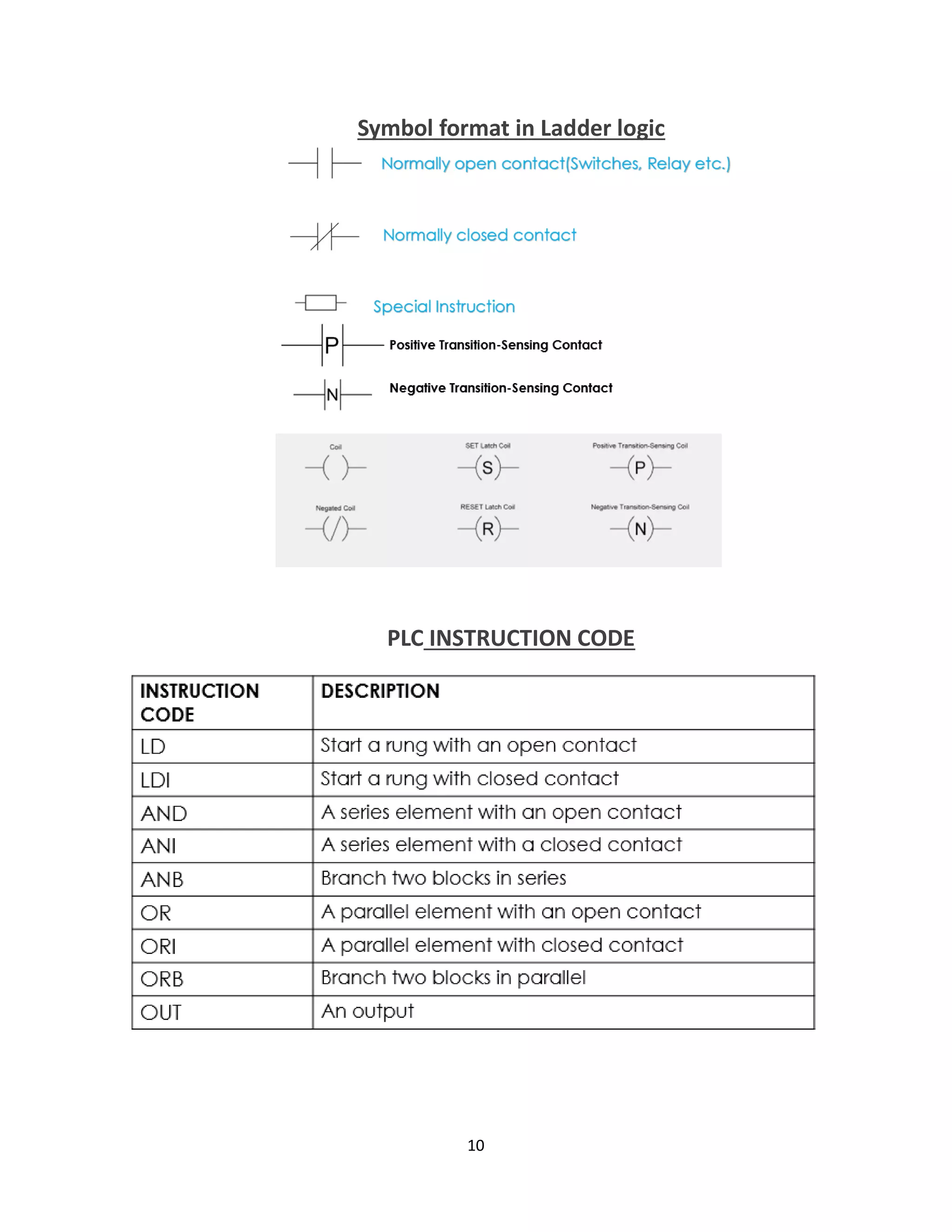
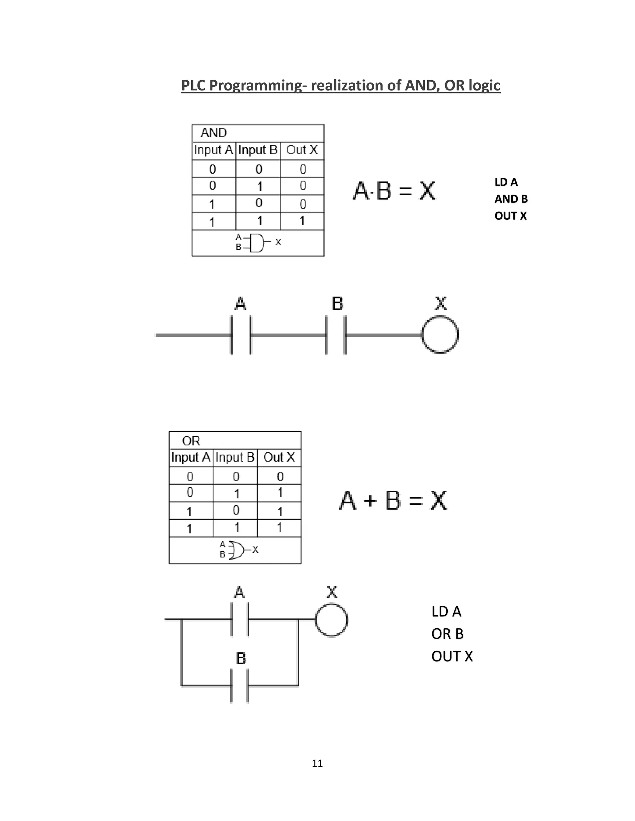
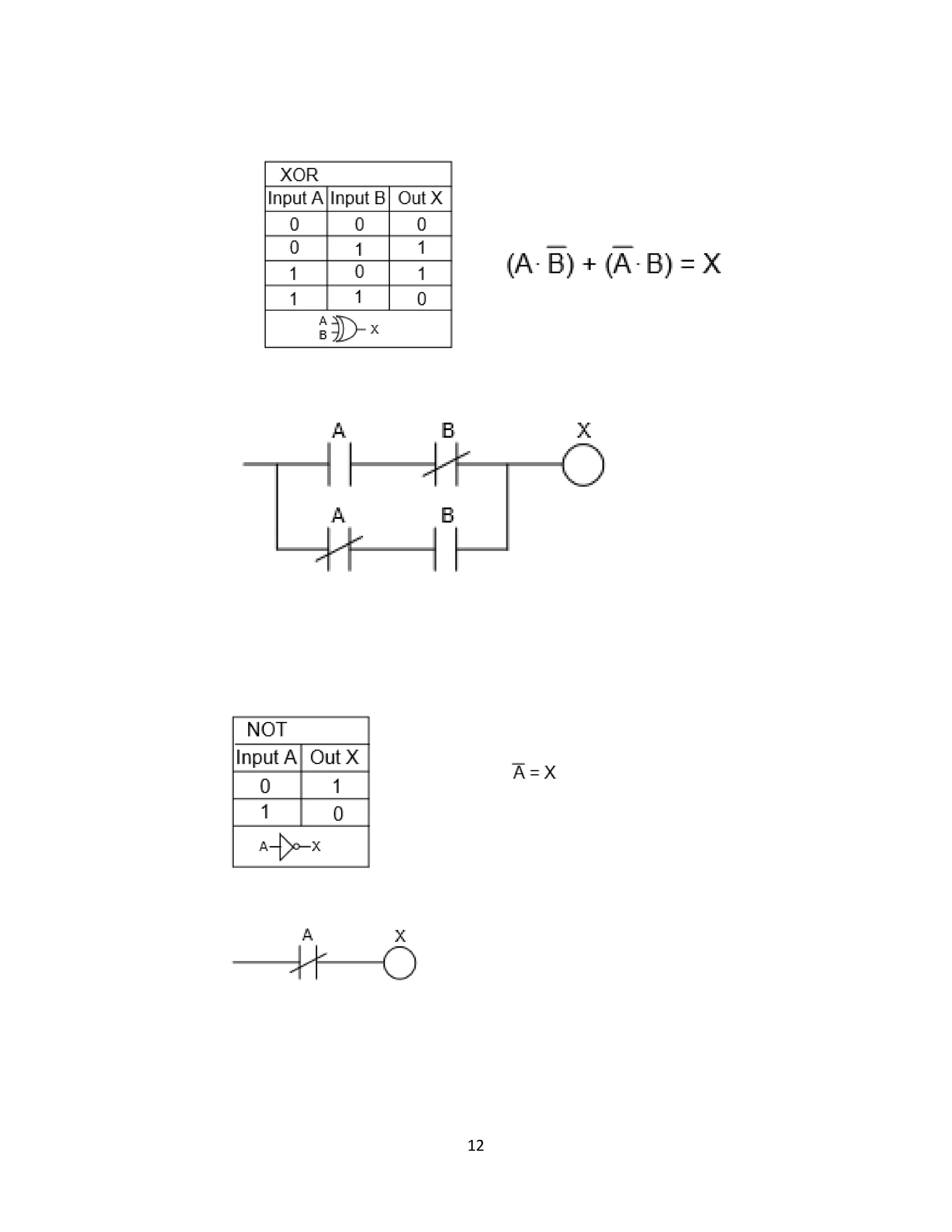
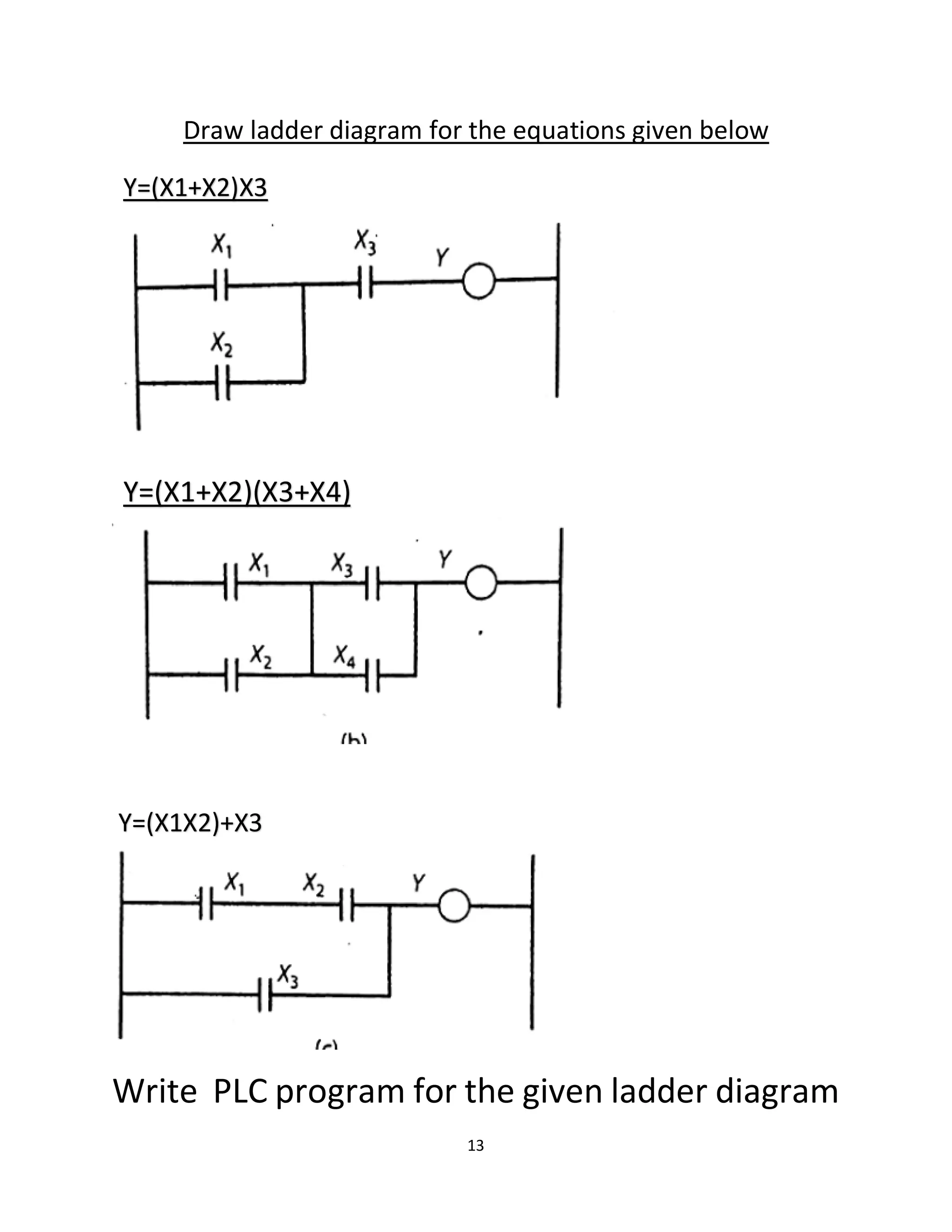
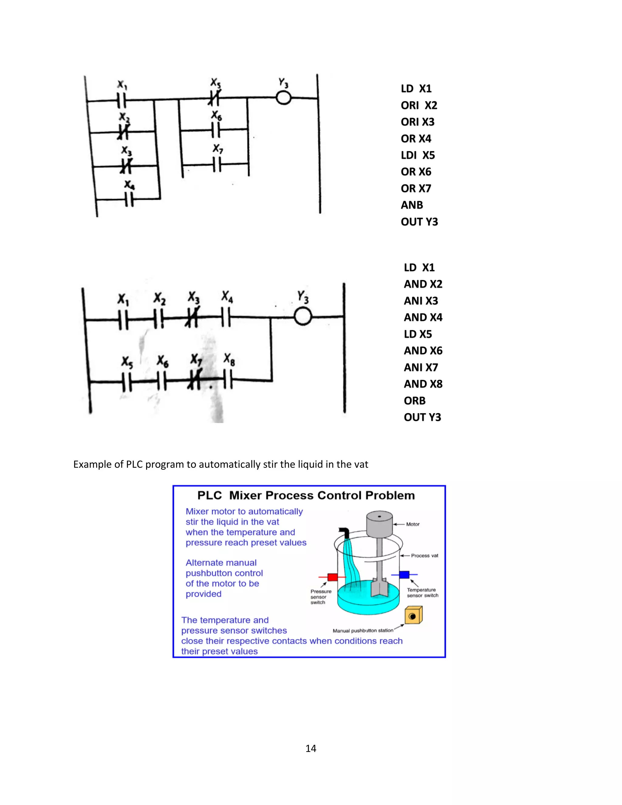
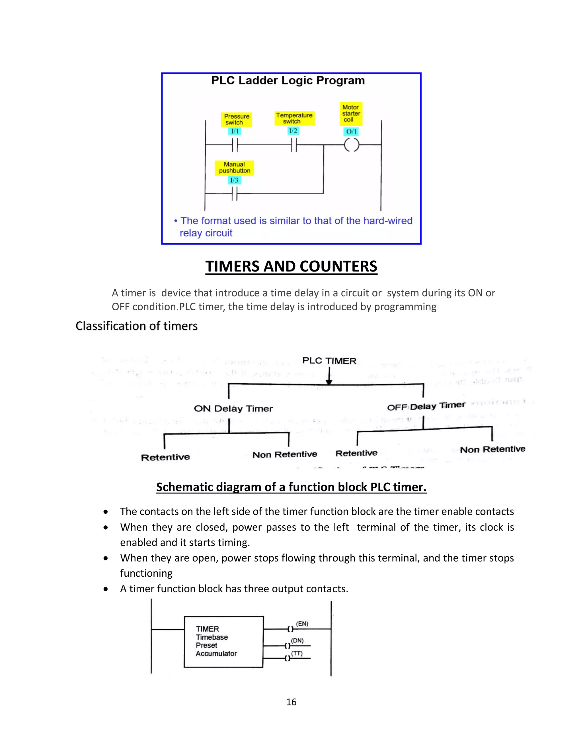
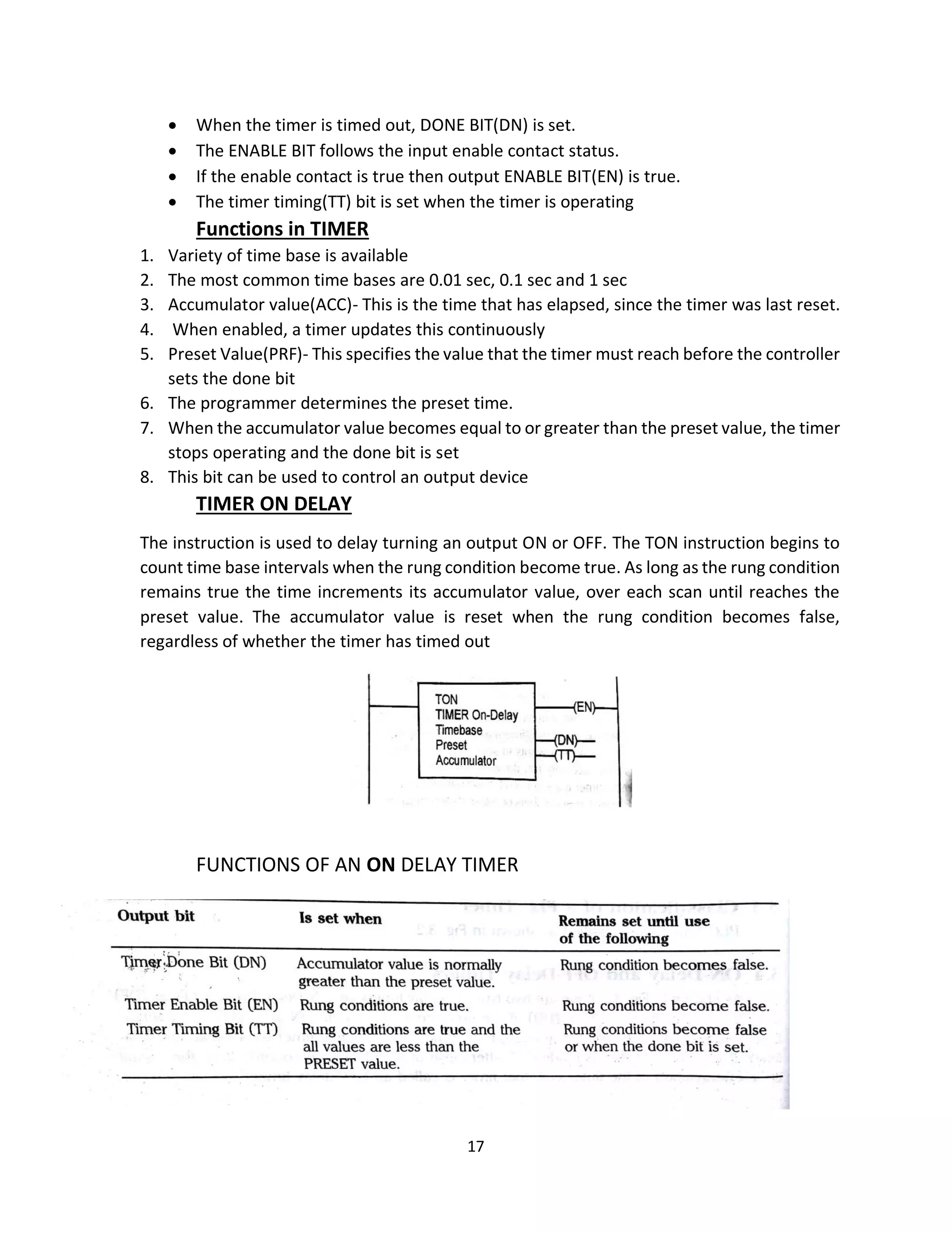
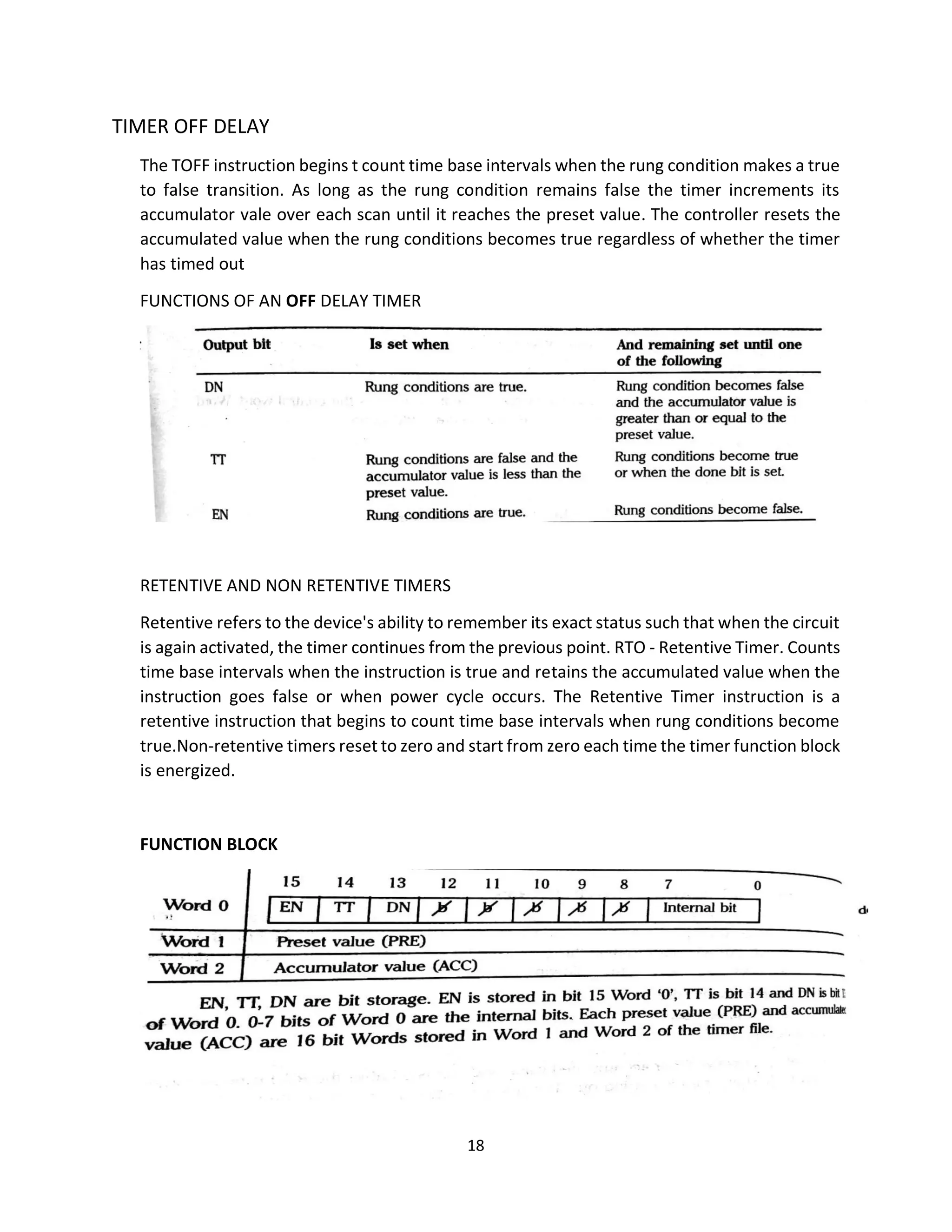
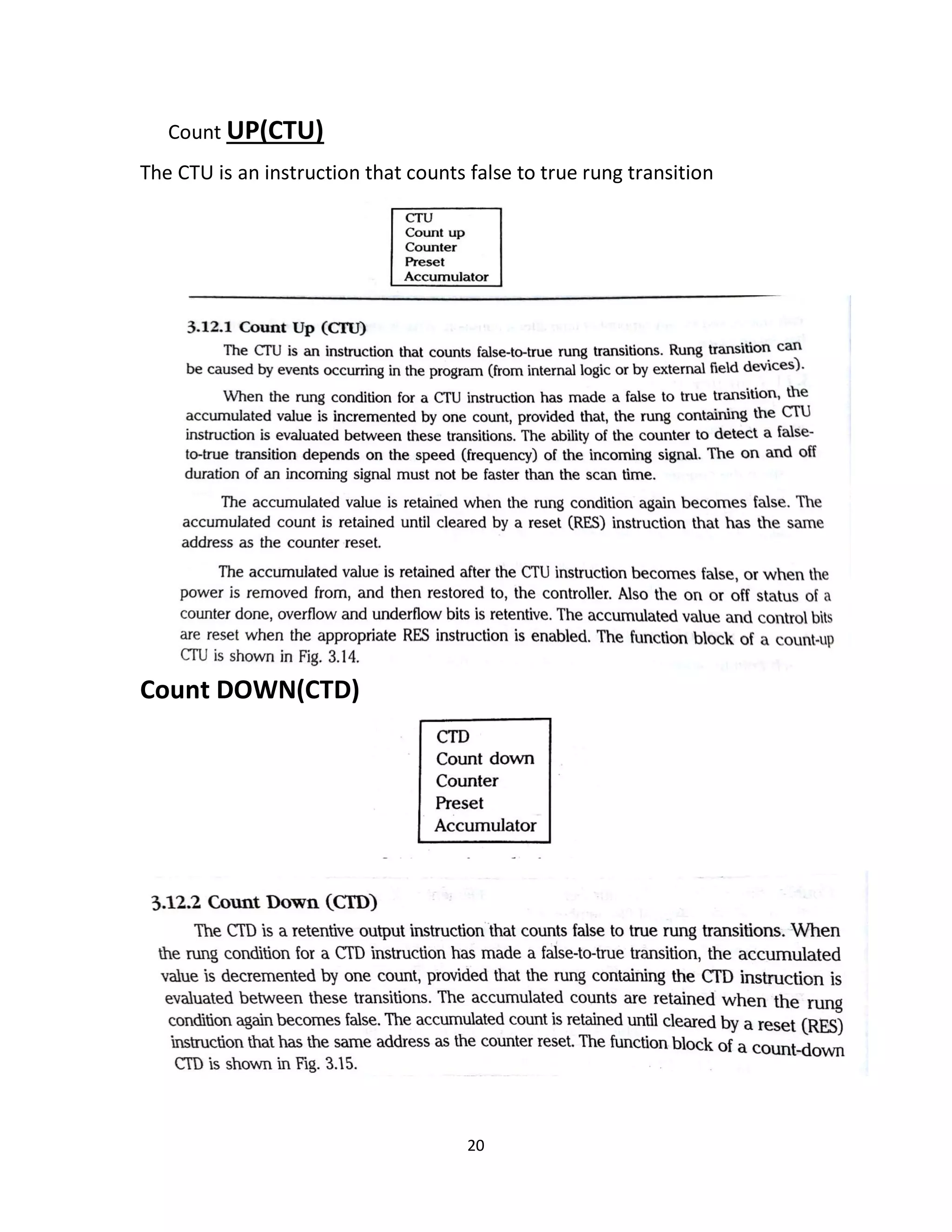
3. Programming concepts like ladder logic are explained, along with basic functions of timers, counters, and their use in sequential and combinational logic problems.