Download as PDF, PPTX
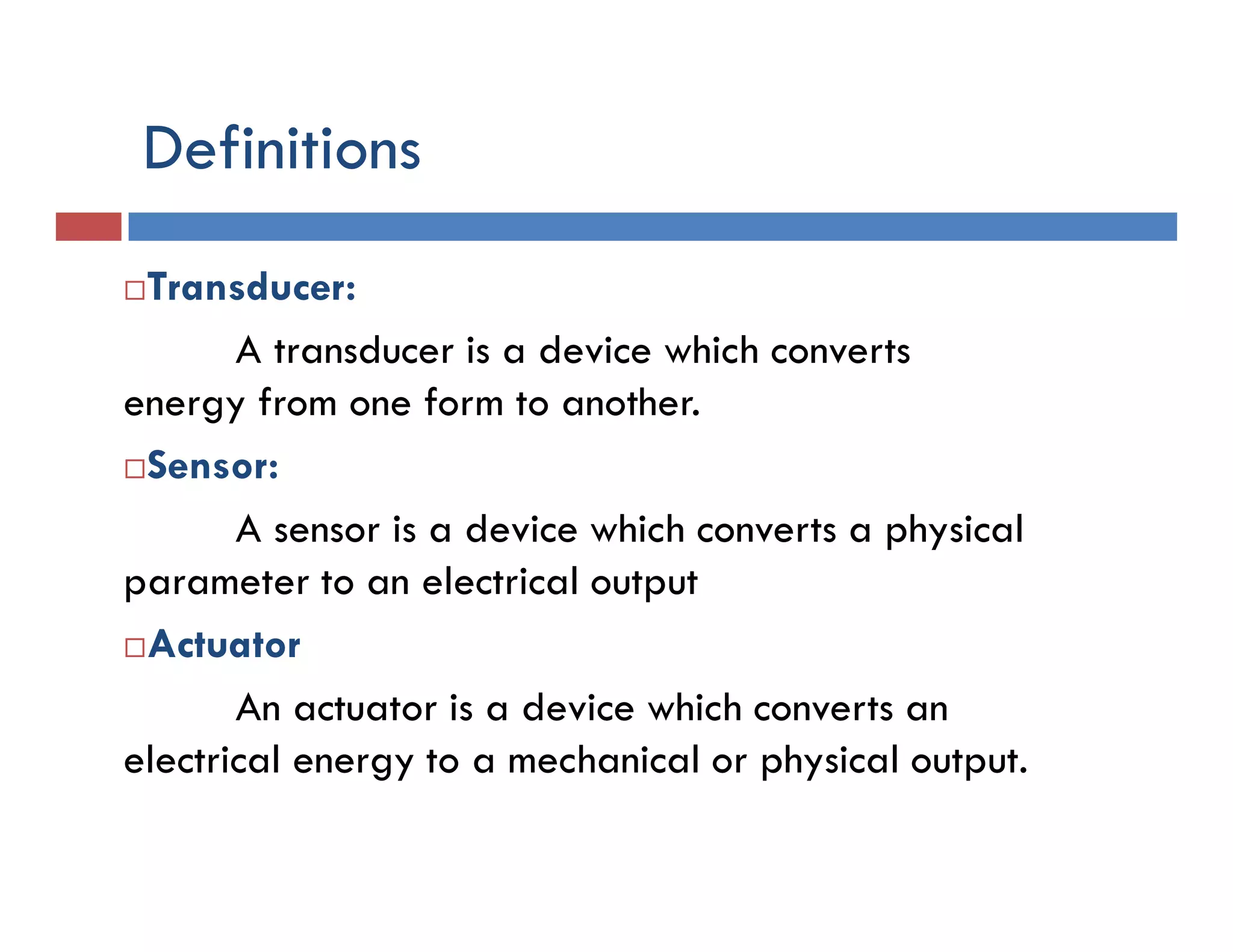
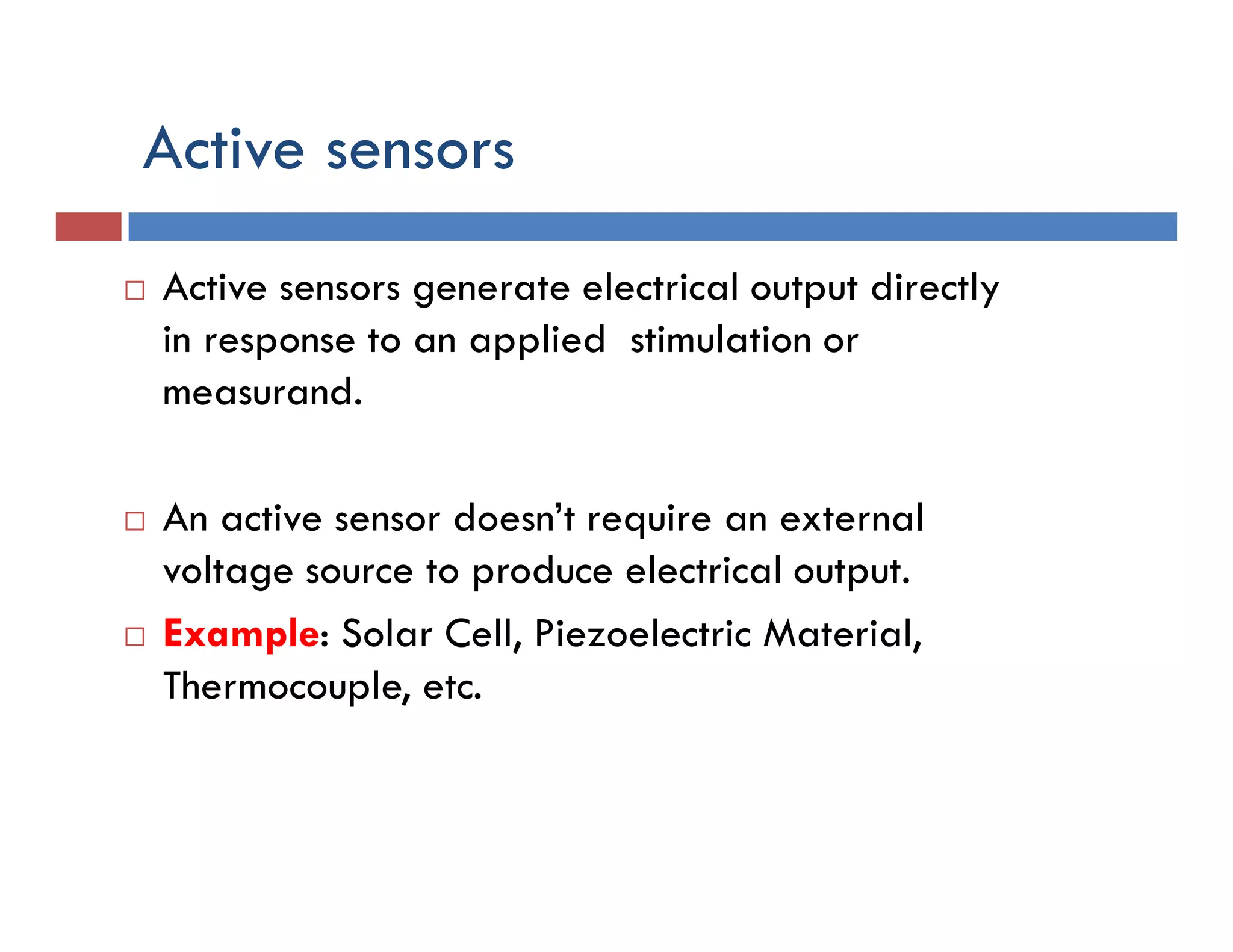
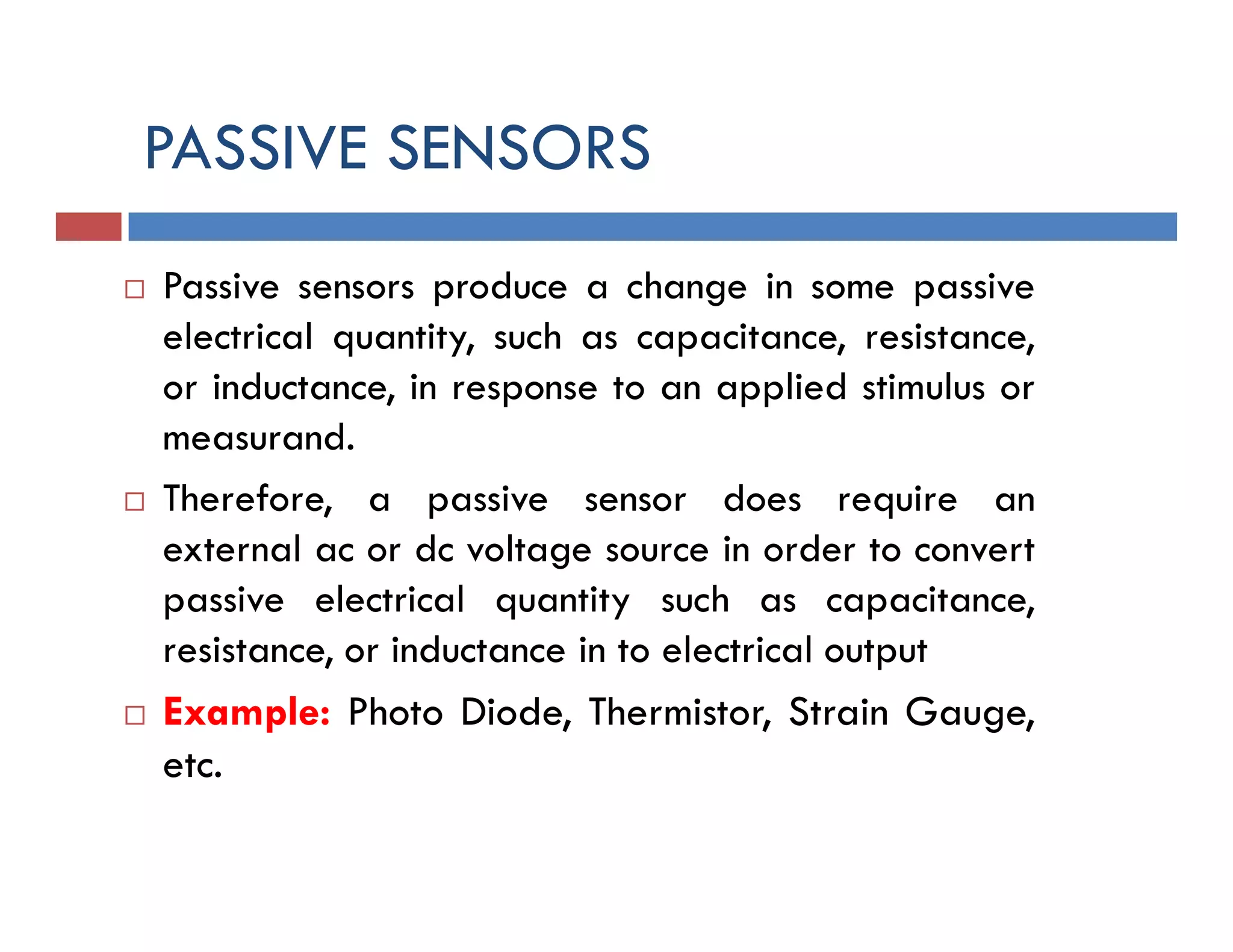
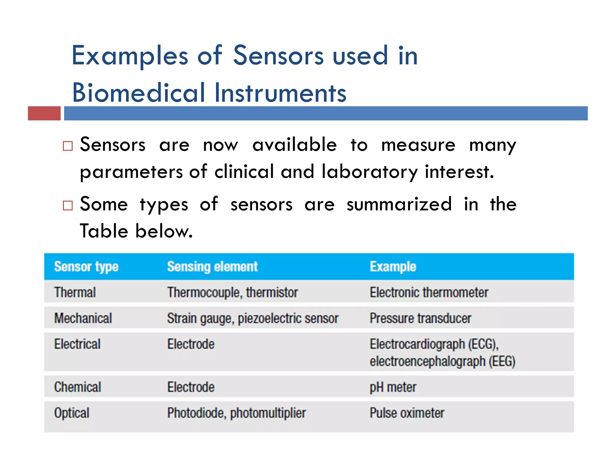
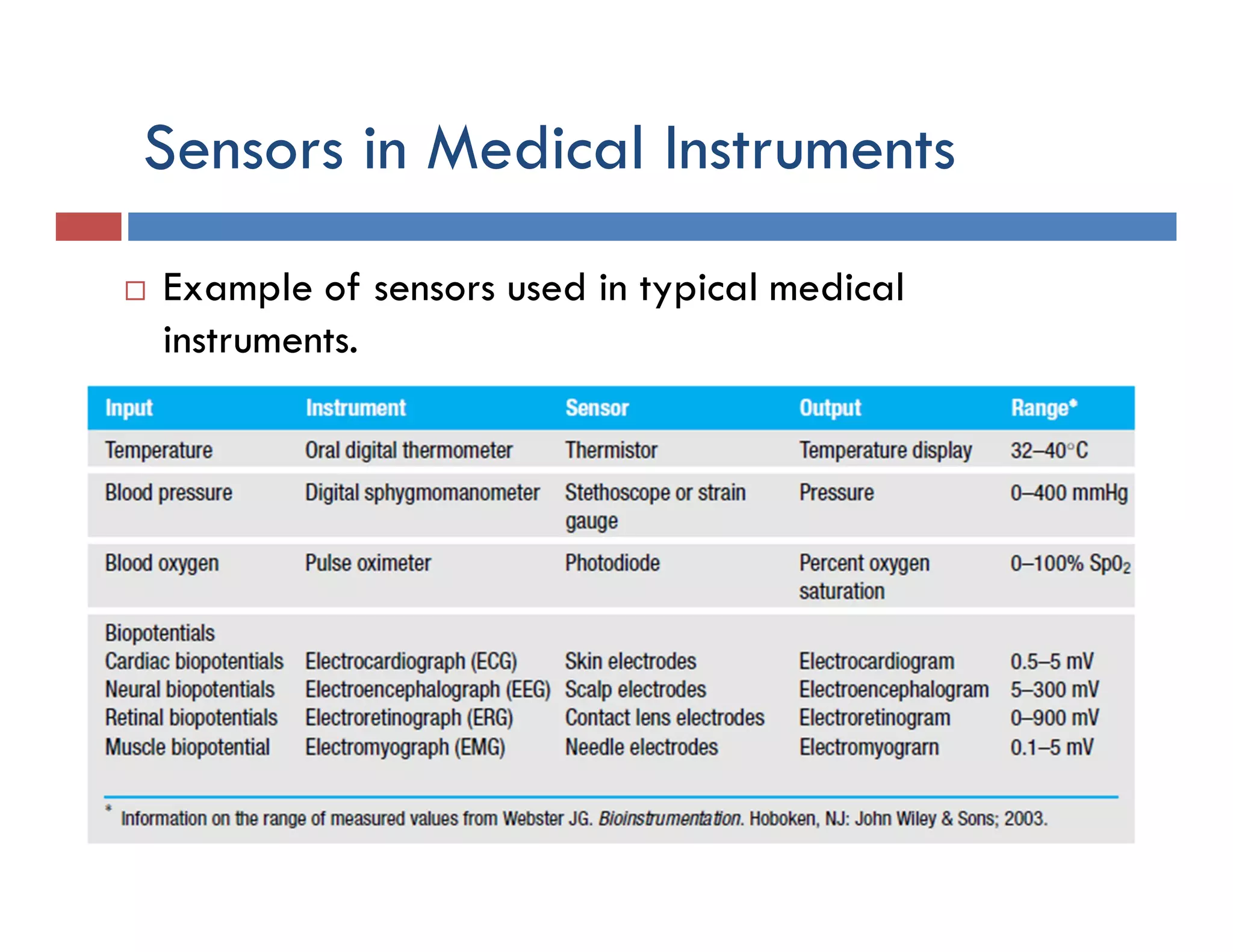


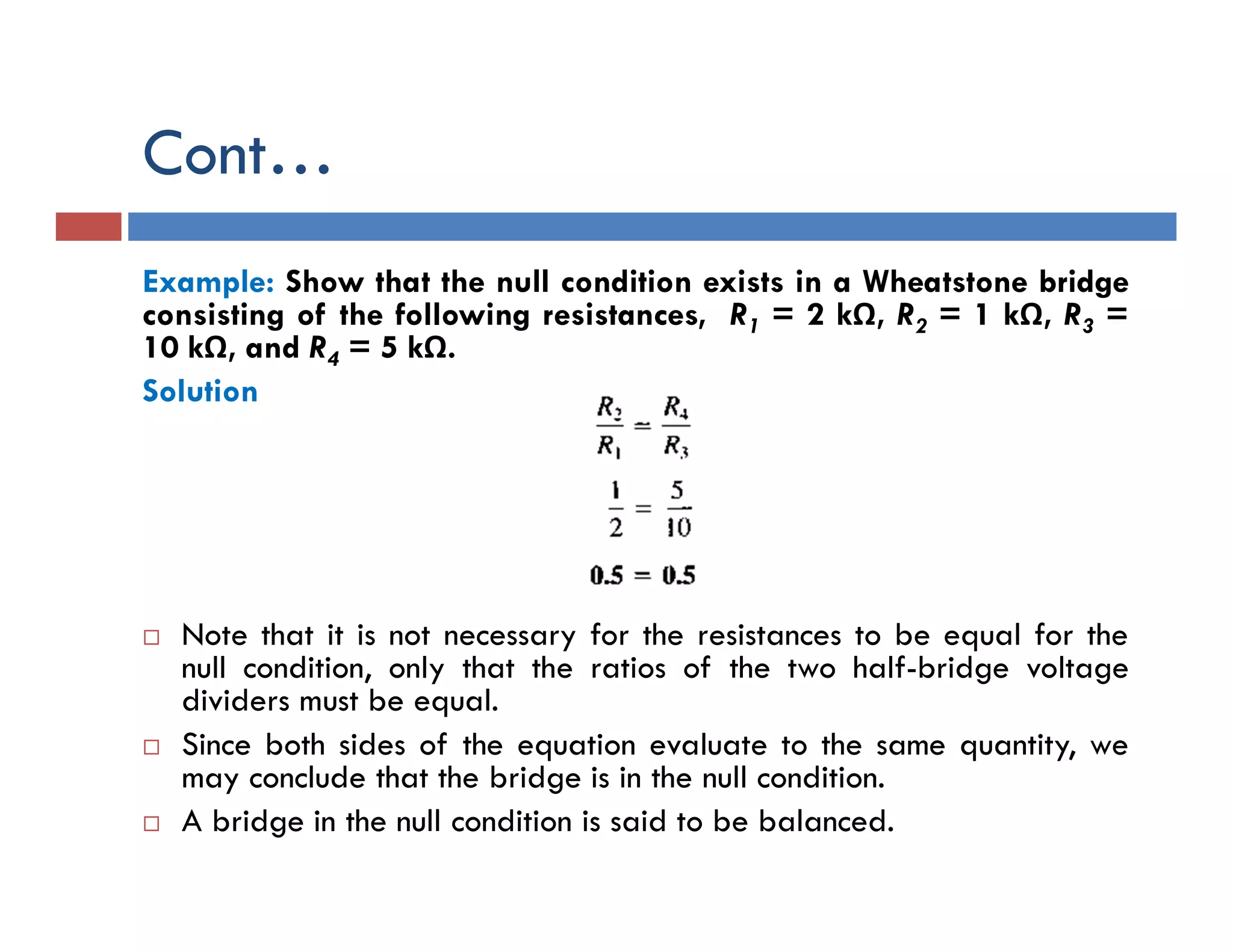

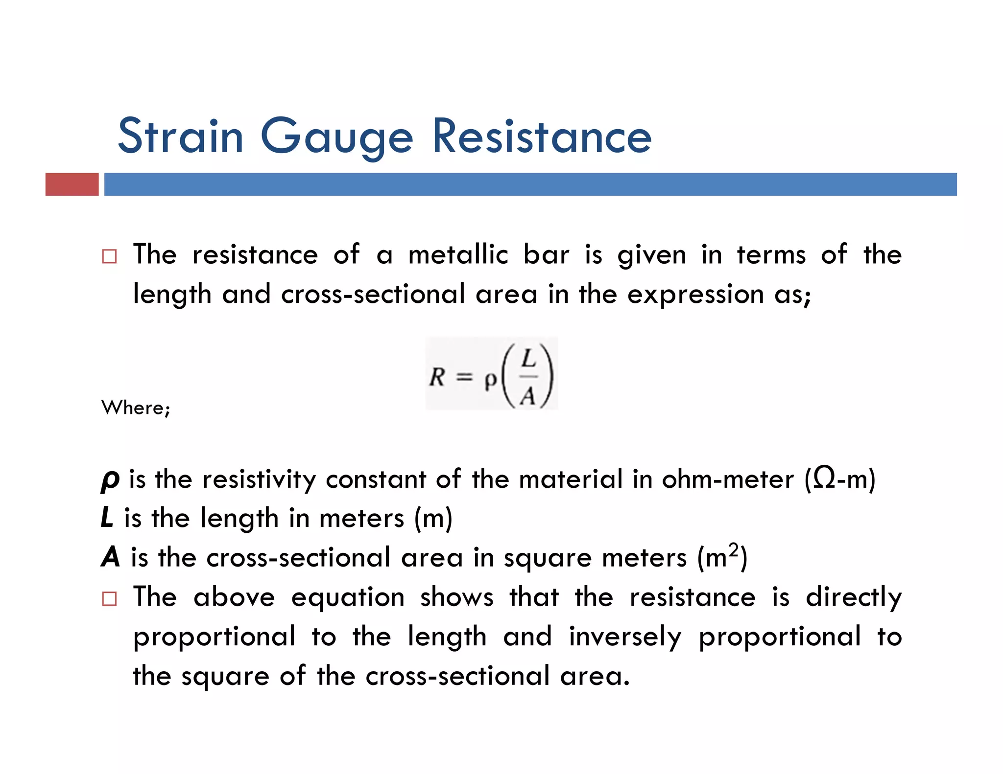
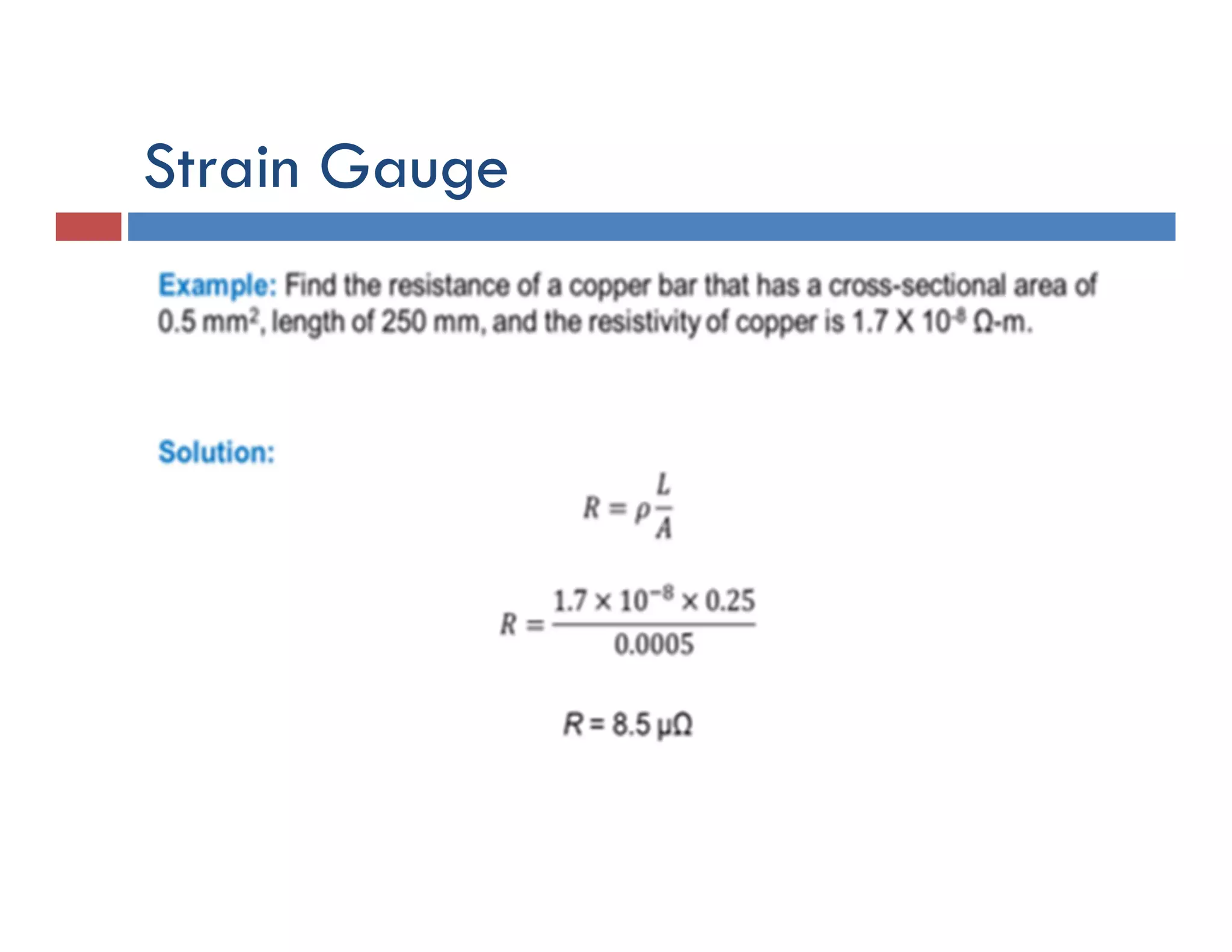
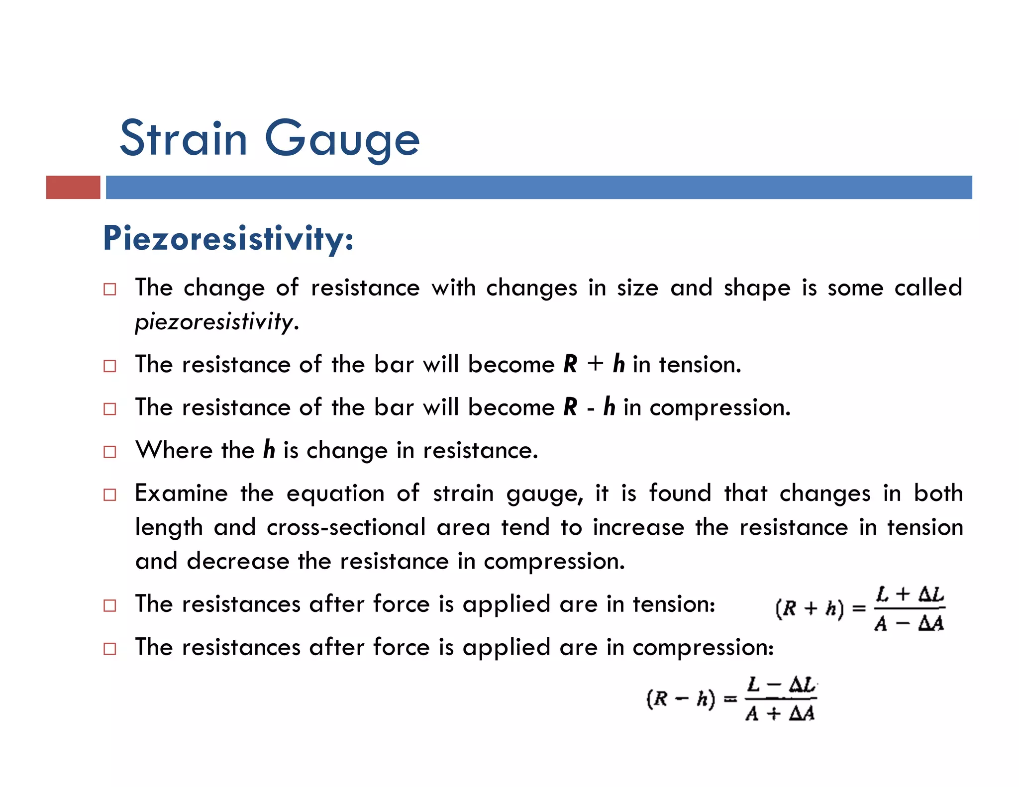


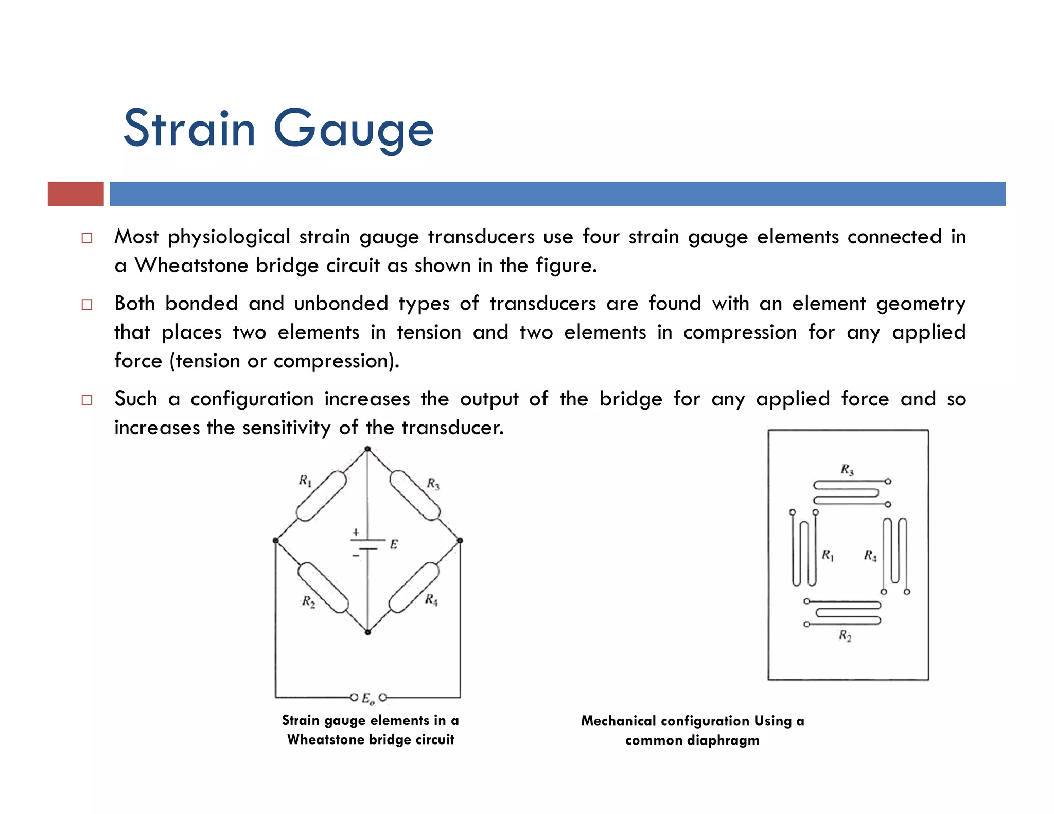


This document provides an overview of sensors used in biomedical devices and systems. It begins by defining key terms like sensor, transducer, and actuator. It then discusses different types of sensors like active and passive sensors. Examples of commonly used biomedical sensors are presented. Sources of sensor error and important sensor terminology are explained. The document provides details on displacement transducers, piezoelectric transducers, and strain gauges. It also describes the Wheatstone bridge circuit configuration often used with biomedical sensors.