Signal Isolation
Technique in Signal
Conditioning
by – Akash shakya
(M.Sc. Electronics)
University of Delhi
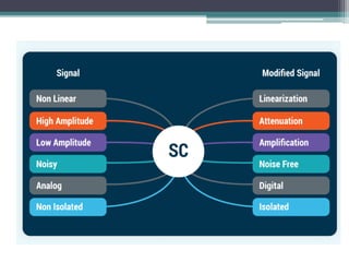
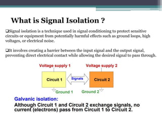
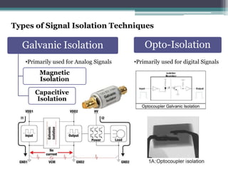
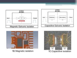
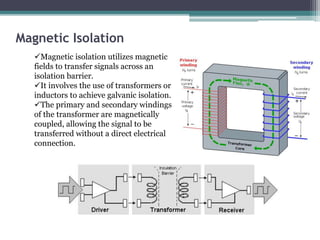
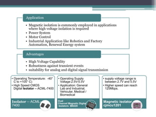
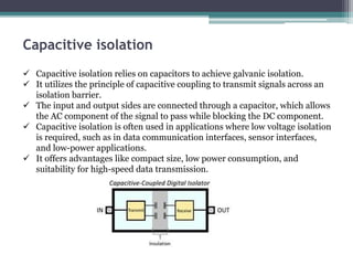
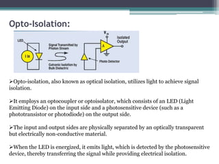
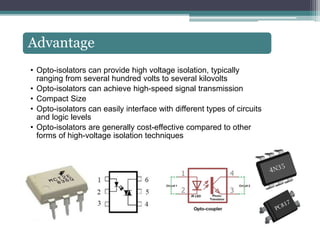
Signal isolation is a technique used in signal conditioning to protect sensitive
circuits or equipment from potentially harmful effects such as ground loops, high
voltages, or electrical noise.
It involves creating a barrier between the input signal and the output signal,
preventing direct electrical contact while allowing the desired signal to pass through.
What is Signal Isolation ?
why we need signal isolation ?
• It prevents the flow of high voltages or currents that
could be hazardous, reducing the risk of electric shock
or damage to components.
Electrical Safety
• Isolation helps minimize the impact of electrical noise
and interference on signals.
Noise Interference
• Ground loops can introduce noise, hum, or voltage
offsets, degrading signal quality and introducing errors.
Signal isolation breaks the ground path between
interconnected devices, effectively eliminating ground
loop problems.
Ground loop Elimination
• It allows for the connection of devices with different
reference potentials or electrical standards, ensuring
proper signal transfer without the risk of damage.
Voltage level
Compatibility
• Isolation provides protection against transient
voltage spikes, surges, or electromagnetic
interference
Protection from
Transients
Ground loop refers to a phenomenon in electrical systems where multiple
devices or circuits are connected to different ground points, resulting in
unwanted currents flowing through the grounding conductors
Ground loops
•Electrical Noise:
Hum Sound
Buzzing Sound
•Voltage Offsets:
The voltage offset can add an offset to the measured values, leading to
inaccurate readings and incorrect data interpretation.
•Signal Distortion:
Effects of Ground loops
Types of Signal Isolation Techniques
Galvanic Isolation
Magnetic
Isolation
Capacitive
Isolation
Opto-Isolation
•Primarily used for digital Signals
•Primarily used for Analog Signals
Magnetic Isolation
Magnetic isolation utilizes magnetic
fields to transfer signals across an
isolation barrier.
It involves the use of transformers or
inductors to achieve galvanic isolation.
The primary and secondary windings
of the transformer are magnetically
coupled, allowing the signal to be
transferred without a direct electrical
connection.
• Magnetic isolation is commonly employed in applications
where high voltage isolation is required
• Power System
• Motor Control
• Industrial Application like Robotics and Factory
Automation, Renewal Energy system
Application
• High Voltage Capability
• Robustness against transient events
• suitability for analog and digital signal transmission
Advantages
• Operating Temperature: -40°
C to +105° C)
• High Speed CMOS
Digital Isolator -- ACML-7400
Isolator -- ACML-
7400
• Operating Supply
Voltage:2.5V-5.5V
• Application: General
Lab and Industrial,
Vehicular, Medical /
Biomedical
Dual
Channel Magnetic Digital
Isolators IB8220
• supply voltage range is
between 2.7V and 5.5V
• Higher speed can reach
125Mbps.
Magnetic isolator
cjmcu1201
Capacitive isolation
 Capacitive isolation relies on capacitors to achieve galvanic isolation.
 It utilizes the principle of capacitive coupling to transmit signals across an
isolation barrier.
 The input and output sides are connected through a capacitor, which allows
the AC component of the signal to pass while blocking the DC component.
 Capacitive isolation is often used in applications where low voltage isolation
is required, such as in data communication interfaces, sensor interfaces,
and low-power applications.
 It offers advantages like compact size, low power consumption, and
suitability for high-speed data transmission.
Opto-Isolation:
Opto-isolation, also known as optical isolation, utilizes light to achieve signal
isolation.
It employs an optocoupler or optoisolator, which consists of an LED (Light
Emitting Diode) on the input side and a photosensitive device (such as a
phototransistor or photodiode) on the output side.
The input and output sides are physically separated by an optically transparent
but electrically non-conductive material.
When the LED is energized, it emits light, which is detected by the photosensitive
device, thereby transferring the signal while providing electrical isolation.
Advantage
• Opto-isolators can provide high voltage isolation, typically
ranging from several hundred volts to several kilovolts
• Opto-isolators can achieve high-speed signal transmission
• Compact Size
• Opto-isolators can easily interface with different types of circuits
and logic levels
• Opto-isolators are generally cost-effective compared to other
forms of high-voltage isolation techniques
Signal Isolation Technique.pptx

Signal Isolation Technique.pptx

  • 1.
    Signal Isolation Technique inSignal Conditioning by – Akash shakya (M.Sc. Electronics) University of Delhi
  • 3.
    Signal isolation isa technique used in signal conditioning to protect sensitive circuits or equipment from potentially harmful effects such as ground loops, high voltages, or electrical noise. It involves creating a barrier between the input signal and the output signal, preventing direct electrical contact while allowing the desired signal to pass through. What is Signal Isolation ?
  • 4.
    why we needsignal isolation ? • It prevents the flow of high voltages or currents that could be hazardous, reducing the risk of electric shock or damage to components. Electrical Safety • Isolation helps minimize the impact of electrical noise and interference on signals. Noise Interference • Ground loops can introduce noise, hum, or voltage offsets, degrading signal quality and introducing errors. Signal isolation breaks the ground path between interconnected devices, effectively eliminating ground loop problems. Ground loop Elimination • It allows for the connection of devices with different reference potentials or electrical standards, ensuring proper signal transfer without the risk of damage. Voltage level Compatibility • Isolation provides protection against transient voltage spikes, surges, or electromagnetic interference Protection from Transients
  • 5.
    Ground loop refersto a phenomenon in electrical systems where multiple devices or circuits are connected to different ground points, resulting in unwanted currents flowing through the grounding conductors Ground loops
  • 6.
    •Electrical Noise: Hum Sound BuzzingSound •Voltage Offsets: The voltage offset can add an offset to the measured values, leading to inaccurate readings and incorrect data interpretation. •Signal Distortion: Effects of Ground loops
  • 7.
    Types of SignalIsolation Techniques Galvanic Isolation Magnetic Isolation Capacitive Isolation Opto-Isolation •Primarily used for digital Signals •Primarily used for Analog Signals
  • 9.
    Magnetic Isolation Magnetic isolationutilizes magnetic fields to transfer signals across an isolation barrier. It involves the use of transformers or inductors to achieve galvanic isolation. The primary and secondary windings of the transformer are magnetically coupled, allowing the signal to be transferred without a direct electrical connection.
  • 10.
    • Magnetic isolationis commonly employed in applications where high voltage isolation is required • Power System • Motor Control • Industrial Application like Robotics and Factory Automation, Renewal Energy system Application • High Voltage Capability • Robustness against transient events • suitability for analog and digital signal transmission Advantages • Operating Temperature: -40° C to +105° C) • High Speed CMOS Digital Isolator -- ACML-7400 Isolator -- ACML- 7400 • Operating Supply Voltage:2.5V-5.5V • Application: General Lab and Industrial, Vehicular, Medical / Biomedical Dual Channel Magnetic Digital Isolators IB8220 • supply voltage range is between 2.7V and 5.5V • Higher speed can reach 125Mbps. Magnetic isolator cjmcu1201
  • 11.
    Capacitive isolation  Capacitiveisolation relies on capacitors to achieve galvanic isolation.  It utilizes the principle of capacitive coupling to transmit signals across an isolation barrier.  The input and output sides are connected through a capacitor, which allows the AC component of the signal to pass while blocking the DC component.  Capacitive isolation is often used in applications where low voltage isolation is required, such as in data communication interfaces, sensor interfaces, and low-power applications.  It offers advantages like compact size, low power consumption, and suitability for high-speed data transmission.
  • 12.
    Opto-Isolation: Opto-isolation, also knownas optical isolation, utilizes light to achieve signal isolation. It employs an optocoupler or optoisolator, which consists of an LED (Light Emitting Diode) on the input side and a photosensitive device (such as a phototransistor or photodiode) on the output side. The input and output sides are physically separated by an optically transparent but electrically non-conductive material. When the LED is energized, it emits light, which is detected by the photosensitive device, thereby transferring the signal while providing electrical isolation.
  • 13.
    Advantage • Opto-isolators canprovide high voltage isolation, typically ranging from several hundred volts to several kilovolts • Opto-isolators can achieve high-speed signal transmission • Compact Size • Opto-isolators can easily interface with different types of circuits and logic levels • Opto-isolators are generally cost-effective compared to other forms of high-voltage isolation techniques