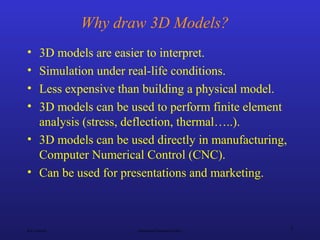
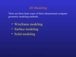
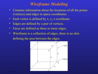
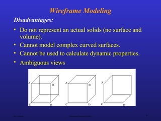
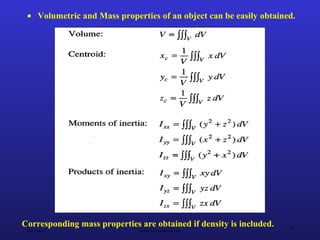
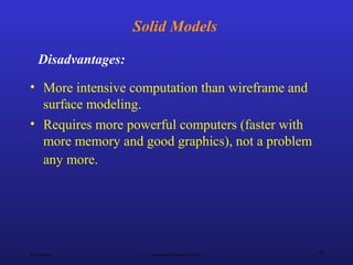
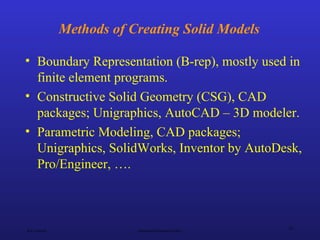
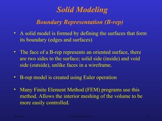
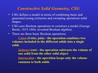
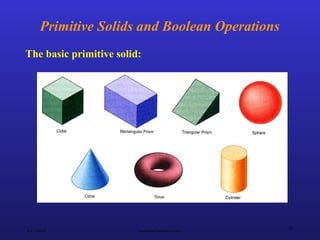
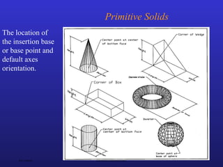
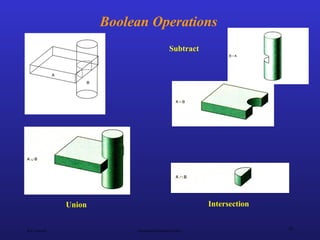
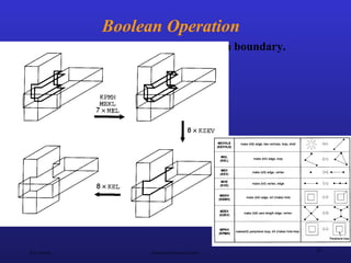
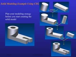
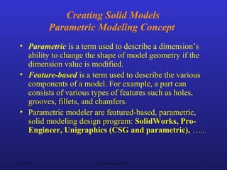
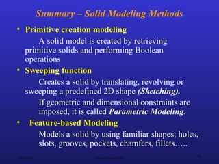
This document discusses different methods of 3D modeling, including wireframe modeling, surface modeling, and solid modeling. It provides details on each modeling method, including their advantages and disadvantages. For example, wireframe modeling only contains edge information and cannot represent actual solids, while solid modeling defines enclosed volumes and allows simulation under real-life conditions. The document also covers specific solid modeling techniques like boundary representation and constructive solid geometry, as well as parametric modeling concepts.
The document discusses different methods for modeling solid objects in 3D, including constructive solid geometry (CSG) and boundary representation (B-Rep). CSG uses boolean operations on primitive solids, represented as a tree structure, while B-Rep defines solids by their enclosing faces, edges and vertices with topological connectivity. Both have advantages such as unambiguous definitions but also challenges around complexity, storage or modeling restrictions. Hybrid approaches combine benefits of both methods.
Top down assembly modeling involves first creating an assembly file with a skeleton layout sketch. Parts are then created within the assembly file and assembled using constraints. This approach allows designing from the overall assembly down to individual components. Benefits include having all design information centralized, reducing errors, and better managing large assemblies with thousands of parts. However, more upfront analysis is required compared to the bottom up approach of first creating individual parts separately before assembling them.
Surface modeling represents the surfaces of 3D objects and can be used to model complex shapes like vehicles, ships, and aircraft wings. There are two main types of surface modeling: parametric surfaces and implicit surfaces. Parametric surfaces use a set of equations to define the x, y, and z coordinates as functions of parameters u and v. Common parametric surface types include planes, ruled surfaces, surfaces of revolution, and tabulated cylinders. Implicit surfaces use a single polynomial equation to define the surface. Surface modeling provides more realistic representations than wireframe models and can be used for applications like finite element analysis, machining tool paths, and rendering models.
Unit 3-ME8691 & COMPUTER AIDED DESIGN AND MANUFACTURINGMohanumar S
This document discusses various CAD standards including:
1. Graphical standards like GKS and OpenGL that define graphics primitives and device independence.
2. Data exchange standards like IGES and STEP that define neutral formats for transferring geometric and non-geometric CAD data between systems.
3. Communication standards like LAN and WAN that define how CAD data is transferred over networks between systems.
The goals of CAD standards are to enable interoperability and portability of CAD data across different software and hardware platforms. They aim to support the complete transfer of product description data.
This document discusses synthetic curves used in mechanical CAD. Synthetic curves are needed to model complex curved shapes and allow manipulation by changing control point positions. There are three main types of synthetic curves: Hermite cubic splines, Bezier curves, and B-spline curves. Bezier curves use control points to influence the curve path without requiring the curve to pass through the points. The curve is defined by a polynomial equation involving blending functions. Bezier curves have tangent lines at the start and end points and maintain tangency when control points are moved.
This document summarizes different types of surfaces that are important from a CAD/CAM perspective. It discusses analytic surfaces like planes, ruled surfaces, tabulated surfaces, and surfaces of revolution which are defined by equations. It also discusses synthetic surfaces like Hermite bi-cubic surfaces, Bezier surfaces, B-spline surfaces, Coons surfaces, fillet surfaces, and offset surfaces which are defined by a set of data points and approximated with polynomials. The document provides examples and definitions of each surface type.
Solid modeling represents 3D objects on a computer by providing surfaces and filling in spaces to make objects appear solid. It allows for accurate mass property calculations, hidden surface removal, and shaded renderings. Solid models are the preferred format for CAD as they provide an unambiguous representation that can be used for simulation, analysis of properties like volume and inertia, and manufacturing. There are three main types - wireframe, surface, and solid - with solid models being the most complete representation. Solid modeling has applications in engineering, entertainment, medicine, and more.
Unit 1-ME8691 & COMPUTER AIDED DESIGN AND MANUFACTURINGMohanumar S
This document provides an introduction and syllabus for a course on computer aided design and manufacturing (CAD/CAM). It discusses the product design and manufacturing processes, including sequential and concurrent engineering models. It also describes CAD systems and computer graphics technologies used to design products digitally. This includes topics like 2D and 3D coordinate systems, geometric transformations, line drawing algorithms, and viewing transformations. The goal of the course is to introduce students to how computer technologies are used in the product design and manufacturing fields.
Solid modeling-Sweep Representation and B-representationDestro Destro
Solid modeling is a computer representation of a physical 3D object that allows for its creation and visualization in digital form. A solid model contains both geometric information about the object's shape, size, and angles as well as topological information about how its parts are connected. Solid models provide a more complete representation than earlier wireframe models and can be represented using techniques like boundary representation, sweeps along trajectories, or as polyhedrons with flat faces, edges and vertices.
This document discusses two common parametric surface representations: Hermite bi-cubic surfaces and Bezier surfaces.
Hermite bi-cubic surfaces connect four corner points and eight tangent vectors at the corners, requiring 16 vectors (48 scalars) to determine the surface coefficients. The parametric equation uses polynomials of the parameters u and v.
Bezier surfaces are defined by a set of control points and basic functions of the parameters u and v. The surface passes through the boundary control points but not necessarily through all interior points. Properties include partition of unity and the surface lying within the convex hull of control points.
This document discusses different types of 3D modeling including wireframe models, surface models, and solid models. It focuses on solid modeling which provides a complete, valid, and unambiguous geometric representation of physical objects. Solid models contain geometric and topological data and can be represented using constructive solid geometry (CSG) which constructs objects by combining simpler solid objects called primitives using Boolean set operations like union, intersection, and difference. CSG starts with basic primitives that are combined and recombined to model complex objects.
The document discusses wireframe modeling in computer-aided design. It defines wireframe modeling as consisting only of points and curves without faces. A wireframe model uses a vertex table and edge table to define geometry. Advantages include ease of creation and low hardware/software requirements, while disadvantages include difficulty visualizing designs. The document also covers classifications of curves used in wireframe modeling like analytical, synthetic, and parametric curves. It provides examples of representing common curves like lines, circles, and splines parametrically.
This document provides an introduction to CAD/CAM/CAE. It begins by defining each term: CAD assists in computer-aided design, CAM plans and controls manufacturing through computer interfaces, and CAE applies computer analysis to engineering components. It then discusses how 3D CAD data can be read by CAM software to generate tool paths for CNC machining. The document also defines computer-integrated manufacturing (CIM) as the total integration of CAD/CAM and business operations using computer systems. It provides an overview of how CAD, CAM, and CAE are applied within the overall product design and manufacturing cycle.
1. Numerical control (NC) systems were developed to automate machine tools using programmed sequences of instructions to control machine motions and functions.
2. NC systems use machine control units to read part programs containing coded instructions and translate them into mechanical actions to control machine tools.
3. Modern computer numerical control (CNC) systems provide greater flexibility over early NC systems by using computers to generate part programs and allow real-time adjustments to machine operations.
This document discusses techniques for achieving visual realism in geometric modeling. It covers topics like hidden line removal, hidden surface determination, shading models, transparency, reflection, and camera models. The goal of visual realism is to generate images that capture effects of light interacting with physical objects similarly to how we see the real world. This involves modeling objects and lighting conditions, determining visible surfaces, assigning color to pixels, and creating animated sequences. Realistic images find applications in simulation, design, entertainment, research, and control.
This document discusses graphic standards and provides details about GKS, CORE, IGES, and their use. It explains that GKS is an international standard for 2D graphics and describes its primitives like polyline and text. It also discusses IGES for exchanging CAD models between different software packages through a neutral file format. The document includes an example of drawing a duck using GKS primitives and an IGES file case study.
The document discusses computer aided design and manufacturing (CAD/CAM). It begins by introducing CAD as using computers to assist in design processes like defining geometry, analysis, and optimization. CAM uses computers to plan, manage, and control manufacturing operations. The benefits of CAD/CAM over manual drafting include increased accuracy, easier modification, storage, and sharing of designs. CAD systems require hardware like workstations, computers, and output devices. Graphics software is used for modeling, drafting, analysis and optimization. Computers have influenced manufacturing by allowing for computer monitoring and control of processes as well as manufacturing support applications.
Unit 2-ME8691 & COMPUTER AIDED DESIGN AND MANUFACTURINGMohanumar S
This document discusses different geometric modeling techniques. It describes wireframe modeling where object edges are represented by lines. Surface modeling uses techniques like patches to represent curved surfaces. Solid modeling represents objects as solids to avoid misinterpretation. Constructive solid geometry and boundary representation are two common solid modeling techniques. CSG uses primitives and Boolean operations while boundary representation uses edges, vertices and faces to define boundaries.
CAD - Unit-1 (Fundamentals of Computer Graphics)Priscilla CPG
This document provides an overview of computer-aided design (CAD). It discusses the different types of CAD (2D, 2.5D, and 3D) and how CAD software is used to create and test models. CAD is used in fields like architecture, engineering, and medical design. The document then covers the product design cycle and how CAD/CAM fits within stages like synthesis, analysis, and manufacturing. It also discusses concurrent engineering and the benefits of a collaborative design process. Finally, it explains fundamental CAD concepts like transformations, viewing, clipping algorithms, and the Sutherland-Hodgman area clipping method.
This document discusses different types of geometric modeling methods including wireframe, surface, and solid modeling. Wireframe modeling uses points and lines to define objects but does not represent actual surfaces or volumes. Surface modeling defines the outer surfaces of an object. Solid modeling precisely defines the enclosed volume of an object using its faces, edges, and vertices. Constructive solid geometry and boundary representation are two common solid modeling techniques. CSG uses Boolean operations to combine primitive shapes, while boundary representation stores topological information about faces, edges, and vertices. Feature-based modeling allows shapes to be created through operations like extruding, revolving, sweeping, and filling.
1. The document discusses CAD & CAM and provides an overview of key concepts related to computer-aided design and manufacturing. It covers topics such as the role of computers in industrial manufacturing including pre-processing, monitoring and control, and post-processing support applications.
2. The document also defines CAD as a design process using computer graphics and CAM as using computers to plan, manage and control manufacturing operations. It discusses the product lifecycle in both traditional and CAD/CAM environments.
3. Additionally, the types of production are classified including job shop production, batch production, mass production, and continuous flow processes. The document provides information on different manufacturing industries and production arrangements.
The document summarizes the history and development of numerical control, including its evolution from mechanized machining in the 15th century to computerized numerical control (CNC) in the 20th century. It describes the basic components and functions of NC machines, including the machine control unit, machine tool, control loops unit, and data processing unit. It also discusses the different types of numerical control systems such as conventional NC, direct NC, and computer NC.
The document provides an introduction to CAD/CAM (computer aided design and computer aided manufacturing). It discusses the need for CAD/CAM due to factors like global competition, demand for new products with enhanced features, and short product life cycles. It also describes developments in computers that have enabled the growth of CAD/CAM technologies. CAD is defined as using computers to assist in the design process, while CAM uses computers to plan and control manufacturing operations. The document outlines the benefits of CAD/CAM including improved productivity, quality, communication and databases of standardized parts.
The document discusses the Initial Graphics Exchange Specification (IGES) format, which is a neutral file format used for CAD data exchange between different software packages. It describes the key components of an IGES file, including the start section, global section, directory entry section, parameter data section, and terminal section. The global section provides metadata about the file. The directory entry and parameter data sections define the geometric entities using parameters. Common entities that can be represented include lines, circles, surfaces of revolution. IGES aims to enable translation between different CAD systems by providing a common format for exchange of geometry and topology data.
This document provides an introduction to computer-aided design (CAD). It defines CAD and computer-aided manufacturing (CAM) as using computers to aid in design and manufacturing functions. The document outlines the basic product design cycle and how CAD/CAM can be integrated at various stages, including computer-aided drafting, process planning, and computer-controlled manufacturing. It also describes the basic hardware and software components of CAD systems, including how interactive computer graphics are used to aid designers. Finally, it summarizes the general six-phase design process.
This document provides information about numerical control (NC) and computer numerical control (CNC) machining. It defines NC as using coded programs to automatically operate machines, with CNC adding an onboard computer. The history of NC is described from its origins in 1947 to modern CNC. Key aspects of CNC systems like controllers, programming, and integrated CAD/CAM are summarized. Other machining techniques like EDM and laser cutting are also briefly outlined.
Geometric modeling involves creating mathematical representations of geometric objects using CAD software. There are three main types of geometric models: wireframe models using lines and curves, surface models representing an object's surface, and solid models representing the complete volumetric shape. Solid modeling is now the most common approach as it allows for properties like mass to be calculated and enables applications like finite element analysis. Geometric models can be created using set operations in constructive solid geometry or parametric modeling techniques.
CAD software can be divided based on the modeling technique used, including 2D, basic 3D, sculpted surfaces, and 3D solid modeling. Geometric modeling is a fundamental part of CAD tools and refers to techniques for developing efficient representations of a design's geometric aspects. The main geometric modeling approaches are wireframe modeling, surface modeling, and solid modeling. Solid modeling provides the most complete description of an object's shape, surface, volume, and density.
This document provides an overview of solid modeling schemes and techniques. It discusses six common solid modeling representations: spatial enumeration, cell decomposition, boundary representation, sweep methods, primitive instancing, and constructive solid geometry. It focuses on the last three techniques, which are most commonly used in modeling packages. Constructive solid geometry uses basic shapes combined with Boolean operations. Boundary representation describes a solid using its enclosing faces, edges and vertices. The document provides examples of both techniques and discusses how solid models allow designers to determine important properties and make design changes more easily compared to other modeling types.
The document discusses different types of geometric models used in modeling including wireframe models, surface models, and solid models. It provides details on each type of model, including their advantages and disadvantages. Wireframe models are the simplest but use the least amount of memory and are easy to create. Surface models are more complex but provide more geometric constraints for engineering applications. Solid models provide the most complete representation and allow calculation of mass properties. The document also discusses different modeling approaches like constructive solid geometry (CSG) and boundary representation (B-rep) used for solid modeling.
The document discusses different modeling techniques in CAD, with the most advanced being 3D solid modeling. It describes the three main approaches to 3D modeling as wireframe modeling, surface modeling, and solid modeling. Solid modeling represents objects most completely by constructing actual 3D geometry and assigning material properties, allowing representation of mass properties and photorealistic appearance.
This document discusses different methods for representing 3D models, including:
- Traditional representations using engineering drawings had weaknesses like ambiguity.
- Computer representations include wireframe geometry, surface representations using tabulated, ruled or swept surfaces, and solid modeling using constructive solid geometry (CSG) or boundary representation (B-rep).
- Surface modeling overcomes some ambiguities of wireframes by specifying surfaces, but is computationally demanding.
- Solid modeling with CSG uses primitives and boolean operations, while B-rep ensures topological consistency of faces, edges and vertices.
- B-rep is more popular than CSG due to limitations of CSG for displays and easier conversion from CSG to
This document discusses computer integrated manufacturing and CAD/CAM modeling techniques. It introduces wireframe, surface, and solid modeling approaches used in geometric modeling. Wireframe models represent objects with edges, while surface modeling uses surfaces defined by vertices and edges. Solid modeling represents objects as bounded 3D volumes divided space into interior and exterior regions. The document then discusses modeling primitives, drawing entities, and algorithms for drawing lines and circles in computer graphics. It concludes by introducing the concept of representing curves and surfaces through implicit and parametric equations.
Geometric modeling is an important part of CAD systems. There are several techniques for geometric modeling including wireframe modeling, surface modeling, and solid modeling. Solid modeling uses half-spaces and boolean operations to define objects by their volume and boundaries. Constructive solid geometry (CSG) and boundary representation (B-rep) are two common solid modeling techniques. CSG uses predefined geometric primitives and boolean operations to combine them. B-rep represents solids as collections of boundary surfaces and records the geometry and topology of the surfaces.
Geometric modeling is a fundamental CAD technique that allows for the complete representation of parts, including their geometry and topology. There are several techniques for geometric modeling, including wireframe modeling, surface modeling, and solid modeling. Solid modeling uses half-spaces and Boolean operations to represent parts as volumes. Common solid modeling techniques are Constructive Solid Geometry (CSG) and Boundary Representation (B-rep). CSG uses primitives and Boolean operations to combine them into a modeling tree, while B-rep represents parts using their boundary surfaces and connectivity. Feature-based, parametric modeling further advanced modeling by using modeling features instead of basic primitives. Geometric modeling continues to evolve with new challenges like modeling porous media and biomedical
1) Geometric modeling is a fundamental CAD technique that represents objects using points, lines, curves, surfaces or solids.
2) Early techniques included wireframe and surface modeling but they were ambiguous and could not fully support engineering activities like stress analysis.
3) Solid modeling uses half-spaces and Boolean operations to unambiguously represent objects spatially and allow full engineering analysis.
1) Geometric modeling is a fundamental CAD technique that represents objects using points, lines, curves, surfaces or solids.
2) Early techniques included wireframe and surface modeling but they were ambiguous and lacked topological data.
3) Solid modeling techniques like CSG and B-Rep overcome these issues by representing objects unambiguously using their volume and topology.
4) Feature-based modeling further advanced CAD by modeling objects parametrically using high-level features like holes and rounds.
This document discusses different types of geometric modeling methods including wireframe, surface, and solid modeling. Wireframe modeling uses points and lines to define objects but does not represent actual surfaces or volumes. Surface modeling defines the outer surfaces of an object. Solid modeling precisely defines the enclosed volume of an object using its faces, edges, and vertices. Constructive solid geometry and boundary representation are two common solid modeling techniques. CSG uses Boolean operations to combine primitive shapes, while boundary representation precisely defines the boundaries and topology of a model.
Geometric modeling is a fundamental technique in CAD. There are several techniques including wireframe modeling, surface modeling, and solid modeling. Wireframe models only use points and curves, while surface models add topology. Solid models provide complete spatial representations using half-spaces and boundary representations (B-rep). Constructive solid geometry (CSG) builds models from primitives using Boolean operations, while B-rep defines models by their surfaces. Parametric, feature-based modeling in systems like Pro/E uses sketches, extrusions, and features to efficiently generate complex models.
This document provides information about solid modeling and drafting presented by Mr. H.B. Wagh. It discusses topics like solid modeling methods, geometry and topology in solid modeling, wireframe vs solid modeling, solid modeling primitives and features, constructive solid geometry, boundary representation, sweeping operations, assembly modeling, and design for manufacturing and assembly principles. Methods of solid modeling discussed include constructive solid geometry using Boolean operations, and boundary representation using vertices, edges, faces and Euler's equation.
Engineering drawings are technical drawings used to define requirements for engineered items. They contain various views, dimensions, and details. There are different types of engineering drawings for different fields like machine drawings, structural drawings, and electrical drawings. Engineering drawings are based on geometric drawings and are important for communicating design ideas, analyzing designs, stimulating further design, and supporting manufacturing. They contain various elements like lines, scales, dimensions, projections, and symbols to convey important information about an engineering design.
This document covers the basics of engineering design. It discusses engineering drawings, including part drawings and assembly drawings. It also discusses projections, scales, units, geometric dimensioning and tolerancing symbols, engineering change notices, title blocks, and using a drawing grid for accuracy. The document provides examples and descriptions to explain these core design concepts. It is intended to teach students the fundamentals of technical drawing and visualization that are essential for engineering design work.
Cst training core module - antenna - (2)Marina Natsir
This document provides an overview of CST Studio Suite, a 3D electromagnetic simulation software. It discusses CST's history and products. It also outlines the software's modeling tools like shapes, curves, and boolean operations. Solvers for time and frequency domain simulations are introduced. Finally, the document describes help resources like documentation, tutorials, and customer support.
The document provides information about vocational training at the Indian Railway station in Agra Cantt. It discusses:
1. The training helps students learn about the various systems used at the station including transformers, feeders, traction motors, and overhead electrification systems.
2. Key components discussed include the 25kV autotransformer system used on overhead lines, oil-filled transformers that help insulate and cool internal parts, and pantographs that draw electricity from overhead catenaries to power train motors.
3. Indian Railways uses both 1.5kV DC and 25kV AC electrification systems, with the voltages used varying based on the region.
This document provides an overview of various latest technologies including nano-technology, sixth sense technology, 4G technology, and blue eyes technology. It describes nano-technology as the study of controlling matter on an atomic or molecular scale and discusses some medical applications. Sixth sense technology is described as a wearable gesture interface that augments the physical world with digital information using hand gestures. It works by using a camera, projector, and mirror coupled in a pendant to capture gestures, process the information, and project images onto surfaces. 4G technology is defined as an extension of 3G providing higher bandwidth and more services through high quality audio/video streaming over the internet. Blue eyes technology aims to build machines that can observe and identify user actions
The document provides details about railway coaches in Indian Railways. It discusses maintenance schedules, wheel profiles and defects, types of coaches including ICF and LHB, components like axles, brake discs, brake shoes, air brake systems, bogie frames, body shells, windows, and water tanks. It also describes the Controlled Discharge Toilet System and Coach Repair Workshop in Harnaut, Bihar.
This document provides an overview of electronic control systems in high-tech vehicles. It discusses the electronic control module that receives sensor data and controls various systems. It describes the electronic fuel injection and ignition systems that are controlled by sensors and the ECM to optimize fuel efficiency and reduce emissions. It also discusses the electronic exhaust system and how catalytic converters use oxidation and reduction catalysts to reduce harmful emissions exiting the vehicle.
A gas turbine works by compressing air, mixing it with fuel and igniting it to produce hot exhaust gases that drive the turbine and generate power. It has an upstream compressor coupled to a downstream turbine with a combustion chamber in between. Gas turbines operate on the Brayton cycle and may be open or closed systems. They are used in power plants, vehicles, and other applications due to their high power-to-weight ratio and ability to operate on different fuels.
The document discusses modern trends in internal combustion engines to make them more economical, environmentally friendly, and safer. It outlines technologies like direct fuel injection, variable valve timing and lift, turbocharging and supercharging, hybrid engines, and rotating liner engines. These technologies allow for more precise fuel delivery, improved engine efficiency, lower emissions, and enhanced performance. While alternative powertrains are emerging, internal combustion engines equipped with modern solutions will likely continue powering most vehicles.
Google announced its first fully functional driverless car ready for testing on public roads, marking a breakthrough in automotive technology. Automakers are also developing automated manual transmissions, vehicle-to-vehicle communication technologies, and advanced driver assistance systems using sensors and automatic braking to increase safety and prevent collisions. Meanwhile, new infotainment systems are allowing smartphone-like interfaces in vehicles, and materials like aluminum are making cars lighter and more fuel efficient.
The document discusses various technologies related to natural gas vehicles (NGVs). It describes that NGVs use compressed natural gas (CNG) or liquefied natural gas (LNG) as fuel. The document then discusses the components of NGV engines and fuel systems, the types of vehicles that can run on natural gas including dedicated NGVs and bi-fuel NGVs, examples of NGV models, and obstacles and solutions to wider adoption of NGVs. It concludes that natural gas combustion produces fewer emissions and may be cheaper than gasoline.
The document discusses different modes of fracture in materials including ductile fracture, brittle fracture, and the transition between ductile and brittle. It examines fracture initiation and propagation at the microstructural level, including mechanisms such as void nucleation, growth, and coalescence in ductile materials. Factors that influence fracture such as grain structure, inclusions, and impurities are also explored.
Metal forming processes use plastic deformation to change the shape of metal workpieces. Rolling is one of the most common metal forming processes, accounting for around 90% of metal shaping. In rolling, the metal workpiece is passed through one or more sets of rolls, reducing the thickness and changing the cross-sectional area under compressive forces applied by the rolls. The geometry of the final product is determined by the shape and contour of the roll gap. Rolling can be performed hot or cold, and is used to produce a wide variety of parts for structural applications and transportation.
Robotic sensing devices are becoming more common as technology advances. These devices use sensors and computer programs to detect and process information about their environment. They can gather various types of data through their built-in sensors and use that information to guide movements or interactions.
Sheet metal processes involve cutting, bending, and drawing operations. Shearing is the primary cutting operation used to cut sheet metal blanks from large sheets. It involves using a punch and die to cut along a straight line. Bending forms sheet metal by curving it around a straight axis and is done using V-bending or edge bending. Both cutting and bending can result in springback as the sheet tries to return to its original shape after forming. Process parameters like punch and die design, clearance, and lubrication affect the quality of cuts and bends in sheet metal fabrication.
This document discusses creep, which is the time-dependent permanent deformation of materials under constant stress, especially at high temperatures. It identifies the primary mechanisms of creep as diffusion and dislocation climb, which are significant at grain boundaries and in the bulk. Creep tests are described where strain over time is measured under a constant load. Classical creep curves are analyzed to determine steady state creep rates and model parameters. Stress rupture curves map time to failure at different stresses and temperatures. The threshold for creep in an alloy is given as 40% of its melting temperature. An example calculates if lead would creep at room temperature. Creep of ice is also discussed.
The document discusses casting processes and the importance of fluid flow. It describes the components of a gating system including the sprue, runner, ingates and riser. It explains that the gating system helps trap contaminants in the molten metal and regulates flow into the mold cavity to ensure proper solidification. The document also covers topics like riser design and function, types of gates, permeability, and cleaning and finishing of castings.
This lecture discusses introductory mechanics models and constitutive models for biomaterials. The objectives are to establish biomaterial constitutive models, determine biomechanical response to load, analyze prosthetic design, and estimate health status of living tissues under stress. The lecture covers introductory mechanics modeling including stress analysis, normal and pure bending. Methods of biomechanics including analytical, experimental, and numerical techniques like FEM are presented. Constitutive models including elastic behavior, Hooke's law, elastic constants, material anisotropy, orthotropy, transverse isotropy, and isotropy are discussed.
This document discusses various common defects that can occur in sand castings, their causes, and how to minimize them. It describes defects such as misruns and cold shuts caused by improper filling before solidification. Shrinkage faults result from inadequate feeding due to poor gating/risering design or solidification issues. Rat tails and buckles are caused by compressed sand layers from heat expansion. Core shifts are from improper core support. Remedies involve design improvements and controlling variables like pouring temperature and solidification.
The Sherline Model 5400 milling machine has a table size of 2.75" x 13" and can fit in a small home machine shop. It has X, Y, and Z travel distances of 8.38", 5", and 6.25" respectively. The milling machine comes in several options, including a basic model, one with a digital readout, a CNC-ready version, and a complete CNC package with computer and software.
This document discusses various machining processes used to produce complex shapes beyond simple round profiles. It describes milling operations like face milling and slab milling. Milling can produce parts with intricate shapes efficiently using computer numerical control (CNC) machines. Other shaping processes covered include broaching, sawing, and gear cutting. Broaching is well-suited for producing internal and external spline and gear teeth. Gears can be generated through hobbing, shaping, or fine-finished through grinding. The document explores the different machining methods, tools, and economics of producing complex geometries.
Abrasive jet machining is an unconventional machining process that uses a high-velocity stream of abrasive particles suspended in a gas to remove material through erosion. It can machine hard and brittle materials that cannot be cut through conventional processes. The process involves mixing abrasive particles with a pressurized gas and passing them through a nozzle to erode away the workpiece material. It provides advantages like ability to machine heat-sensitive materials without damaging them and capability to cut intricate holes, but has low material removal rates and accuracy issues due to stray cutting.
This document provides guidance on using PowerPoint to design effective presentations. It covers topics like planning content, getting started with design, displaying text and graphics, animating slides, and presenting. The document instructs the reader to follow steps marked "YOUR TURN" to practice applying the tips. It emphasizes organizing information clearly for the audience, using visuals and animation purposefully, and preparing and practicing the presentation.
More from *noT yeT workinG! !M stilL studyinG* (20)
ACEP Magazine edition 4th launched on 05.06.2024Rahul
This document provides information about the third edition of the magazine "Sthapatya" published by the Association of Civil Engineers (Practicing) Aurangabad. It includes messages from current and past presidents of ACEP, memories and photos from past ACEP events, information on life time achievement awards given by ACEP, and a technical article on concrete maintenance, repairs and strengthening. The document highlights activities of ACEP and provides a technical educational article for members.
Introduction- e - waste – definition - sources of e-waste– hazardous substances in e-waste - effects of e-waste on environment and human health- need for e-waste management– e-waste handling rules - waste minimization techniques for managing e-waste – recycling of e-waste - disposal treatment methods of e- waste – mechanism of extraction of precious metal from leaching solution-global Scenario of E-waste – E-waste in India- case studies.
Presentation of IEEE Slovenia CIS (Computational Intelligence Society) Chapte...University of Maribor
Slides from talk presenting:
Aleš Zamuda: Presentation of IEEE Slovenia CIS (Computational Intelligence Society) Chapter and Networking.
Presentation at IcETRAN 2024 session:
"Inter-Society Networking Panel GRSS/MTT-S/CIS
Panel Session: Promoting Connection and Cooperation"
IEEE Slovenia GRSS
IEEE Serbia and Montenegro MTT-S
IEEE Slovenia CIS
11TH INTERNATIONAL CONFERENCE ON ELECTRICAL, ELECTRONIC AND COMPUTING ENGINEERING
3-6 June 2024, Niš, Serbia
DEEP LEARNING FOR SMART GRID INTRUSION DETECTION: A HYBRID CNN-LSTM-BASED MODELgerogepatton
As digital technology becomes more deeply embedded in power systems, protecting the communication
networks of Smart Grids (SG) has emerged as a critical concern. Distributed Network Protocol 3 (DNP3)
represents a multi-tiered application layer protocol extensively utilized in Supervisory Control and Data
Acquisition (SCADA)-based smart grids to facilitate real-time data gathering and control functionalities.
Robust Intrusion Detection Systems (IDS) are necessary for early threat detection and mitigation because
of the interconnection of these networks, which makes them vulnerable to a variety of cyberattacks. To
solve this issue, this paper develops a hybrid Deep Learning (DL) model specifically designed for intrusion
detection in smart grids. The proposed approach is a combination of the Convolutional Neural Network
(CNN) and the Long-Short-Term Memory algorithms (LSTM). We employed a recent intrusion detection
dataset (DNP3), which focuses on unauthorized commands and Denial of Service (DoS) cyberattacks, to
train and test our model. The results of our experiments show that our CNN-LSTM method is much better
at finding smart grid intrusions than other deep learning algorithms used for classification. In addition,
our proposed approach improves accuracy, precision, recall, and F1 score, achieving a high detection
accuracy rate of 99.50%.
Harnessing WebAssembly for Real-time Stateless Streaming PipelinesChristina Lin
Traditionally, dealing with real-time data pipelines has involved significant overhead, even for straightforward tasks like data transformation or masking. However, in this talk, we’ll venture into the dynamic realm of WebAssembly (WASM) and discover how it can revolutionize the creation of stateless streaming pipelines within a Kafka (Redpanda) broker. These pipelines are adept at managing low-latency, high-data-volume scenarios.
Literature Review Basics and Understanding Reference Management.pptxDr Ramhari Poudyal
Three-day training on academic research focuses on analytical tools at United Technical College, supported by the University Grant Commission, Nepal. 24-26 May 2024
5214-1693458878915-Unit 6 2023 to 2024 academic year assignment (AutoRecovere...
Introduction to solid modeling
1. Ken Youssefi Mechanical Engineering Dept.
1
Introduction to Solid Modeling
Parametric Modeling
2. Ken Youssefi Mechanical Engineering Dept.
2
Why draw 3D Models?
• 3D models are easier to interpret.
• Simulation under real-life conditions.
• Less expensive than building a physical model.
• 3D models can be used to perform finite element
analysis (stress, deflection, thermal…..).
• 3D models can be used directly in manufacturing,
Computer Numerical Control (CNC).
• Can be used for presentations and marketing.
3. Ken Youssefi Mechanical Engineering Dept.
3
3D Modeling
• Wireframe modeling
• Surface modeling
• Solid modeling
There are three basic types of three-dimensional computer
geometric modeling methods:
4. Ken Youssefi Mechanical Engineering Dept.
4
Wireframe Modeling
• Contains information about the locations of all the points
(vertices) and edges in space coordinates.
• Each vertex is defined by x, y, z coordinate.
• Edges are defined by a pair of vertices.
• Faces are defined as three or more edges.
• Wireframe is a collection of edges, there is no skin
defining the area between the edges.
5. Ken Youssefi Mechanical Engineering Dept.
5
Wireframe Modeling
• Can quickly and efficiently convey information
than multiview drawings.
• The only lines seen are the intersections of
surfaces.
• Can be used for finite element analysis.
• Can be used as input for CNC machines to
generate simple parts.
• Contain most of the information needed to create
surface, solid and higher order models
Advantages:
6. Ken Youssefi Mechanical Engineering Dept.
6
Wireframe Modeling
• Do not represent an actual solids (no surface and
volume).
• Cannot model complex curved surfaces.
• Cannot be used to calculate dynamic properties.
• Ambiguous views
Disadvantages:
8. Ken Youssefi Mechanical Engineering Dept.
8
Surface Modeling
• Surface models define the surface features, as well
as the edges, of objects.
• A mathematical function describes the path of a
curve (parametric techniques).
• Surfaces are edited as single entities.
A surface model represents the skin of an object,
these skins have no thickness or material type.
9. Ken Youssefi Mechanical Engineering Dept.
9
Surface Modeling
• Eliminates ambiguity and non-uniqueness present in
wireframe models by hiding lines not seen.
• Renders the model for better visualization and
presentation, objects appear more realistic.
• Provides the surface geometry for CNC machining.
• Provides the geometry needed for mold and die design.
• Can be used to design and analyze complex free-formed
surfaces (ship hulls, airplane fuselages, car bodies, …).
• Surface properties such as roughness, color and
reflectivity can be assigned and demonstrated.
Advantages:
10. Ken Youssefi Mechanical Engineering Dept.
10
Surface Modeling
• Surface models provide no information about the
inside of an object.
• Complicated computation, depending on the
number of surfaces
Disadvantages:
11. Ken Youssefi Mechanical Engineering Dept.
11
Solid Models
• Has all the advantages of surface models (uniqueness,
non-ambiguous, realistic, surface profile) plus
volumetric information.
• Allows the designer to create multiple options for a
design.
• 2D standard drawings, assembly drawing and exploded
views are generated form the 3D model.
In the solid modeling, the solid definitions include vertices
(nodes), edges, surfaces, weight, and volume. The model is a
complete and unambiguous representation of a precisely
enclosed and filled volume.
Advantages:
12. Ken Youssefi Mechanical Engineering Dept.
12
Solid Models
• Can easily be exported to different Finite Element
Methods programs for analysis.
• Can be used in newly manufacturing techniques;
computer integrated manufacturing (CIM),
computer aided manufacturing (CAM) and design
for manufacturability ans assembly (DFM, DFA)
• Mass and volumetric properties of an object can
be easily obtained; total mass, mass center, area
and mass moment of inertia, volume, radius of
gyration, …
Advantages:
13. Ken Youssefi Mechanical Engineering Dept.
13
• Volumetric and Mass properties of an object can be easily obtained.
Corresponding mass properties are obtained if density is included.
14. Ken Youssefi Mechanical Engineering Dept.
14
Solid Models
• More intensive computation than wireframe and
surface modeling.
• Requires more powerful computers (faster with
more memory and good graphics), not a problem
any more.
Disadvantages:
15. Ken Youssefi Mechanical Engineering Dept.
15
Methods of Creating Solid Models
• Boundary Representation (B-rep), mostly used in
finite element programs.
• Constructive Solid Geometry (CSG), CAD
packages; Unigraphics, AutoCAD – 3D modeler.
• Parametric Modeling, CAD packages;
Unigraphics, SolidWorks, Inventor by AutoDesk,
Pro/Engineer, ….
16. Ken Youssefi Mechanical Engineering Dept.
16
Solid Modeling
Boundary Representation (B-rep)
• A solid model is formed by defining the surfaces that form
its boundary (edges and surfaces)
• The face of a B-rep represents an oriented surface, there
are two sides to the surface; solid side (inside) and void
side (outside), unlike faces in a wireframe.
• B-rep model is created using Euler operation
• Many Finite Element Method (FEM) programs use this
method. Allows the interior meshing of the volume to be
more easily controlled.
18. Ken Youssefi Mechanical Engineering Dept.
18
Euler Operators
Geometric entities stored in B-Rep data structures are the
shell, face, loop, edge, and vertex.
Operators are needed to manipulate these entities (e.g., an
operator to make an edge, an operator to delete an edge,…)
19. Ken Youssefi Mechanical Engineering Dept.
19
Euler-Poincare Formula
v – e + f – h =2 (s – p)
v represents the number of vortices, e the number of edges, f the
number of faces, h the number of hole loops, s the number of shells
and p the number of passages (through holes of a solid)
Applies to the geometric entities
21. Ken Youssefi Mechanical Engineering Dept.
21
Constructive Solid Geometry, CSG
• CSG defines a model in terms of combining basic and
generated (using extrusion and sweeping operation) solid
shapes.
• CSG uses Boolean operations to construct a model (George
Boole, 1815-1864, invented Boolean algebra).
• There are three basic Boolean operations:
Union (Unite, join) - the operation combines two
volumes included in the different solids into a single
solid.
Subtract (cut) - the operation subtracts the volume of
one solid from the other solid object.
Intersection - the operation keeps only the volume
common to both solids
22. Ken Youssefi Mechanical Engineering Dept.
22
Primitive Solids and Boolean Operations
The basic primitive solid:
23. Ken Youssefi Mechanical Engineering Dept.
23
Primitive Solids
The location of
the insertion base
or base point and
default axes
orientation.
25. Ken Youssefi Mechanical Engineering Dept.
25
Implementing Boolean Operation
Consider solids A and B.
26. Ken Youssefi Mechanical Engineering Dept.
26
Boolean Operation
The intersection curves of all the faces of solid A and B
are calculated. These intersections are inscribed on the
associated faces of the two solids.
27. Ken Youssefi Mechanical Engineering Dept.
27
Boolean Operation
The faces of solid A are classified according to their relative location
with respect to solid B. Each face is tested to determine whether it is
located inside, outside, or on the boundary surface of solid B.
The faces in group A1
are outside solid B, and those of group B1
are
inside solid A.
28. Ken Youssefi Mechanical Engineering Dept.
28
Boolean Operation
Groups of faces are collected according to the specific
Boolean operation and the unnecessary face groups are
eliminated. For example, for union operation, group A1
and
B2
are collected and A2
and B1
are eliminated.
29. Ken Youssefi Mechanical Engineering Dept.
29
Boolean Operation
The two solids are glued at their common boundary.
30. Ken Youssefi Mechanical Engineering Dept.
30
Union
Plan your modeling strategy
before you start creating the
solid model
Solid Modeling Example Using CSG
Cut
Cut
31. Ken Youssefi Mechanical Engineering Dept.
31
Creating Solid Models
Parametric Modeling Concept
• Parametric is a term used to describe a dimension’s
ability to change the shape of model geometry if the
dimension value is modified.
• Feature-based is a term used to describe the various
components of a model. For example, a part can
consists of various types of features such as holes,
grooves, fillets, and chamfers.
• Parametric modeler are featured-based, parametric,
solid modeling design program: SolidWorks, Pro-
Engineer, Unigraphics (CSG and parametric), …..
32. Ken Youssefi Mechanical Engineering Dept.
32
Design Intent
• In parametric modeling, dimensions
control the model.
• Design intent is how your model
will react when dimension values
are changed.
33. Ken Youssefi Mechanical Engineering Dept.
33
Design Intent
Remember that the placement of dimensions is very important
because they are being used to drive the shape of the geometry. If
the 2.5 in. vertical dimension increases, the 2.5 in. flat across the
chamfer will be maintained, but its angle will change.
The drawing shows the intent of the
designer that the inclined plane
(chamfer) should have a flat area
measuring 2.5 inches and that it
should start at a point 1.25 inches
from the base of the drawing. These
parameters are what the designer
deemed significant for this model.
2.50
4.00
1.25
2.50
Example:
34. Ken Youssefi Mechanical Engineering Dept.
34
Design Intent
In this drawing, what is important to
the designer is the vertical location and
horizontal dimension of the chamfer,
rather than the flat of the chamfer.
2.50
4.00
1.25
2.125
In the last drawing, the designer calls
for a specific angle for the chamfer.
In this case the angle of the chamfer
should be dimensioned.
2.50
4.00
1.75
30.0O
36. Ken Youssefi Mechanical Engineering Dept.
36
Design Notes
• Keep in mind that dimensioning scheme can be
changed at any time. You are not locked into a
specific design. You can also design without
dimensioning, rough out a sketch, and then later
go back and fully define it.
• Do not be concerned with dimensioning to datum
or stacked tolerances in the part. Those issues can
be addressed in the drawing layout. Be more
concerned with your design intent.
37. Ken Youssefi Mechanical Engineering Dept.
37
Boolean Versus Parametric Modeling
The ability to go back on some earlier stage in the design
process and make changes by editing a sketch or changing
some dimensions is extremely important to a designer. This is
the main advantage of a parametric (SolidWorks, Unigraphics,
Inventor, Pro-Engineer) over a non-parametric modeler
(AutoCAD 3D modeler – Boolean operation)
38. Ken Youssefi Mechanical Engineering Dept.
38
Boolean Versus Parametric Modeling
Example:
Let’s assume that it is desired to design a part consisting of a
ring with a certain thickness and a series of counterbore holes
along the perimeter.
39. Ken Youssefi Mechanical Engineering Dept.
39
Boolean Versus Parametric Modeling
Boolean operation
Make the base part by creating two
cylinders and subtract the small one
from the large one
Create the solid geometry that will
become the counterbore holes and
generate the pattern.
40. Ken Youssefi Mechanical Engineering Dept.
40
Boolean Versus Parametric Modeling
Position the pattern about the perimeter of the
base part. Locating the holes is critical to
creating an accurate solid model.
What would happen if you had to come back to this part to change
the thickness of the ring or size of the counterbore holes?
Since Boolean operation was used to create the part, changing the
thickness would not increase the height of the holes. There is no
association between the thickness and the hole pattern location.
Subtract the pattern from the base part to
create the actual holes.
41. Ken Youssefi Mechanical Engineering Dept.
41
Boolean Versus Parametric Modeling
Parametric modeling (SolidWorks, ProE, UG, …)
Create the initial base, the ring, by
extruding the profile (circles) in a
particular direction (Pro/E or
SolidWorks) or use primitive solids
and Boolean operation (UG).
Create the counterbore as a feature.
Select the top surface of the ring
and either sketch the two holes and
extrude at different depth or use the
hole feature option.
42. Ken Youssefi Mechanical Engineering Dept.
42
Boolean Versus Parametric Modeling
The next step would be to pattern the
hole. The pattern would actually be
considered a feature in itself, and
would have its set of parametric
variables, such as the number of
copies and the angle between copies.
The model created would be identical to the one created
using Boolean operation, but with intelligence built into
the model.
43. Ken Youssefi Mechanical Engineering Dept.
43
Boolean Versus Parametric Modeling
The true power of parametric modeling shines through when
design changes need to be made. The design modification is
made by simply changing a dimension.
Since the counterbore is associated with the top surface of the
ring, any changes in the thickness of the ring would automatically
be reflected on the counterbore depth.
44. Ken Youssefi Mechanical Engineering Dept.
44
Sketching and Features
• Take the word sketch literally. A sketch should be just
that, a sketch.
• When sketching, it is not necessary to create geometry
with accuracy. Lines, arcs, and additional geometry need
not be created with exact dimensions in mind.
• When the dimensions are added, the sketch will change
size and shape. This is the essence of Parametric
Modeling.
When discussing the mind-set needed for working with
parametric modelers, there are two topics that need to be
expanded: Sketching and Features
Sketching
In short, the sketch need only be the approximate size and shape
of the part being designed. When dimensions and constraints are
added, they will drive the size and the shape of the geometry.
45. Ken Youssefi Mechanical Engineering Dept.
45
Sketching and Features
• Sketched Feature
Features
Create a feature from the sketch by extruding,
revolving, sweeping, lofting and blending.
2.75
2.51.0
.25
.75
Create a 2D sketch.
Revolved feature Extruded feature
47. Ken Youssefi Mechanical Engineering Dept.
47
Sketching and Features
• Applied Feature
Applied feature does not require a sketch.
They are applied directly to the model.
Fillets and chamfers are very common
applied features.
Chamfer
Fillet
48. Ken Youssefi Mechanical Engineering Dept.
48
Summary – Solid Modeling Methods
• Primitive creation modeling
A solid model is created by retrieving
primitive solids and performing Boolean
operations
• Sweeping function
Creates a solid by translating, revolving or
sweeping a predefined 2D shape (Sketching).
If geometric and dimensional constraints are
imposed, it is called Parametric Modeling.
• Feature-based Modeling
Models a solid by using familiar shapes; holes,
slots, grooves, pockets, chamfers, fillets…..
49. Ken Youssefi Mechanical Engineering Dept.
49
Summary – Solid Modeling Methods
• Modifying functions
Rounding (or blending) and lifting.
• Boundary Modeling
Lower entities of a solid (vertices, edges and
faces) are directly manipulated.
50. Ken Youssefi Mechanical Engineering Dept.
50
Sketching
• Take the word sketch literally. A sketch should
be just that, a sketch.
• Sketches are able to capture the designer’s intent
for the part like no other technique.
• The sketch is the best tool for creating solids
because of flexibility in shapes and the ability to
edit.
• Ideal for creating unusual freeform shapes.
51. Ken Youssefi Mechanical Engineering Dept.
51
Sketching
• A sketch is a set of two dimensional curves joined
in a string that when swept or extruded forms a
solid body.
• When sketching it is not necessary to create
geometry with accuracy.
• Lines, arcs, and additional geometry need not be
created with exact dimensions in mind.
52. Ken Youssefi Mechanical Engineering Dept.
52
Sketching
• When the dimensions are added, the sketch will
change size and shape. This is the essence of
parametric modeling
• In short, the sketch need only be the approximate
size and shape of the part being designed. The
geometric constraints and dimensions, when
added, will drive the size and the shape of the
geometry.
• Curves are parametrically associated to each other
and the solid that is created by them.