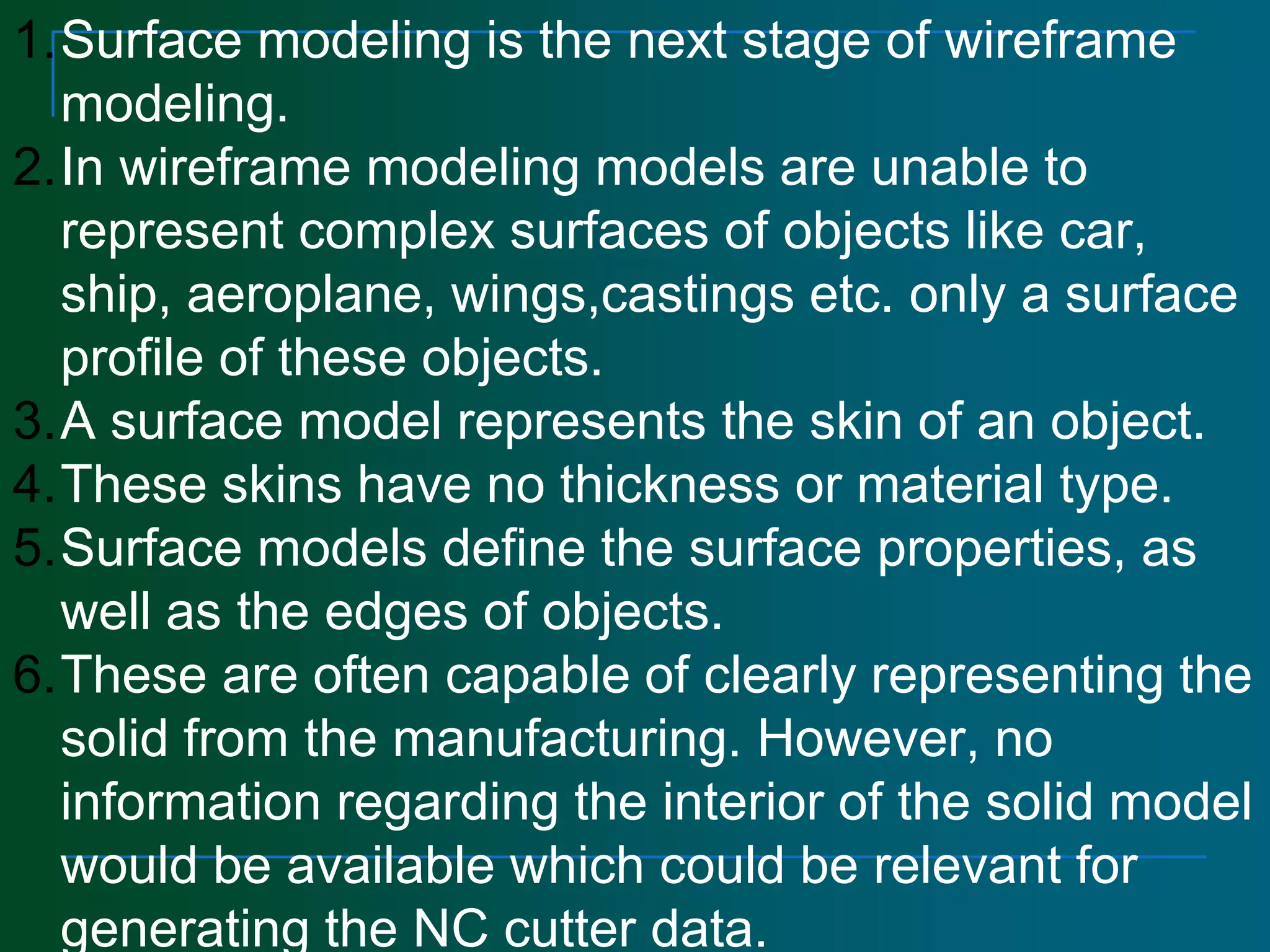
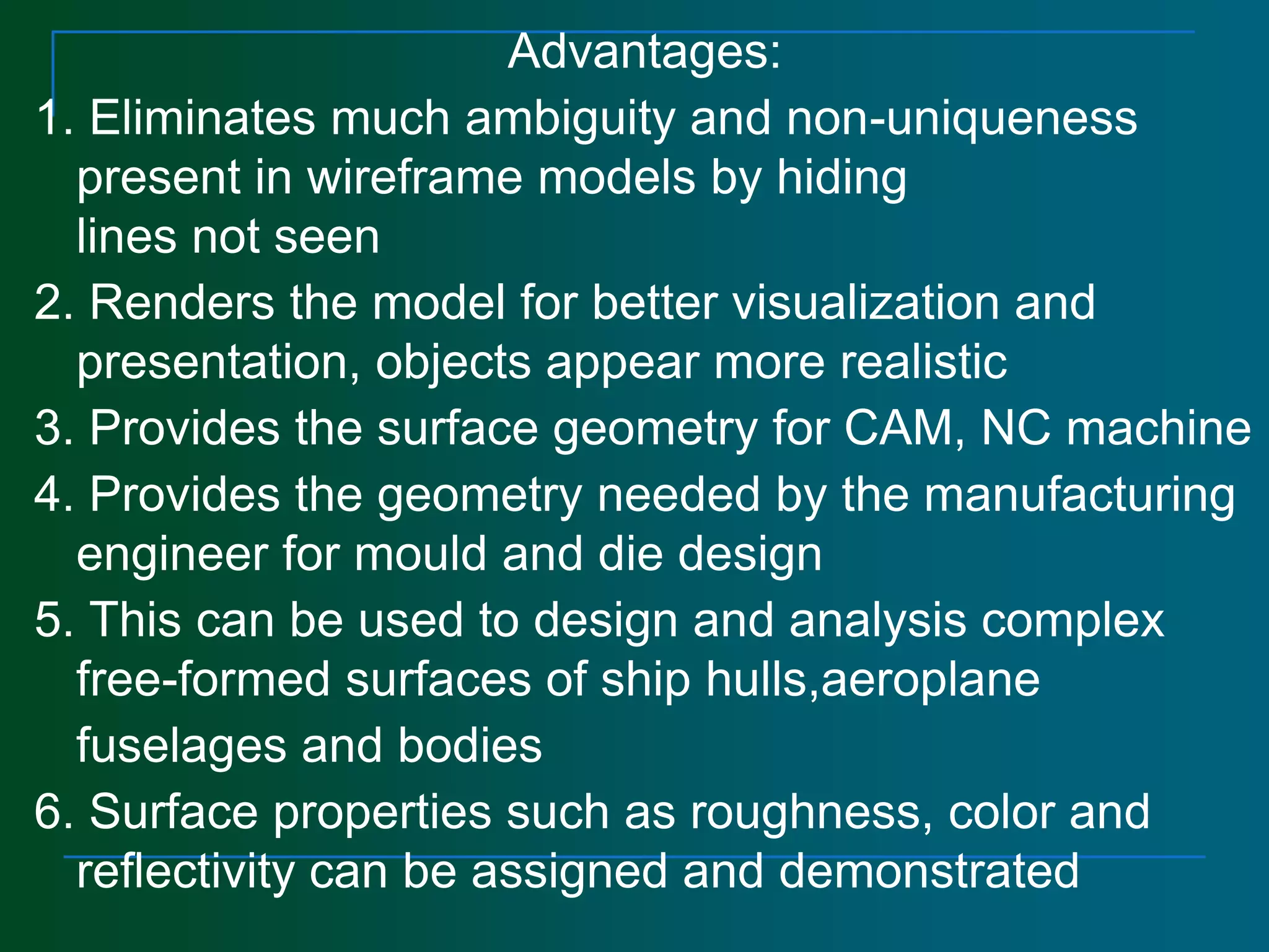
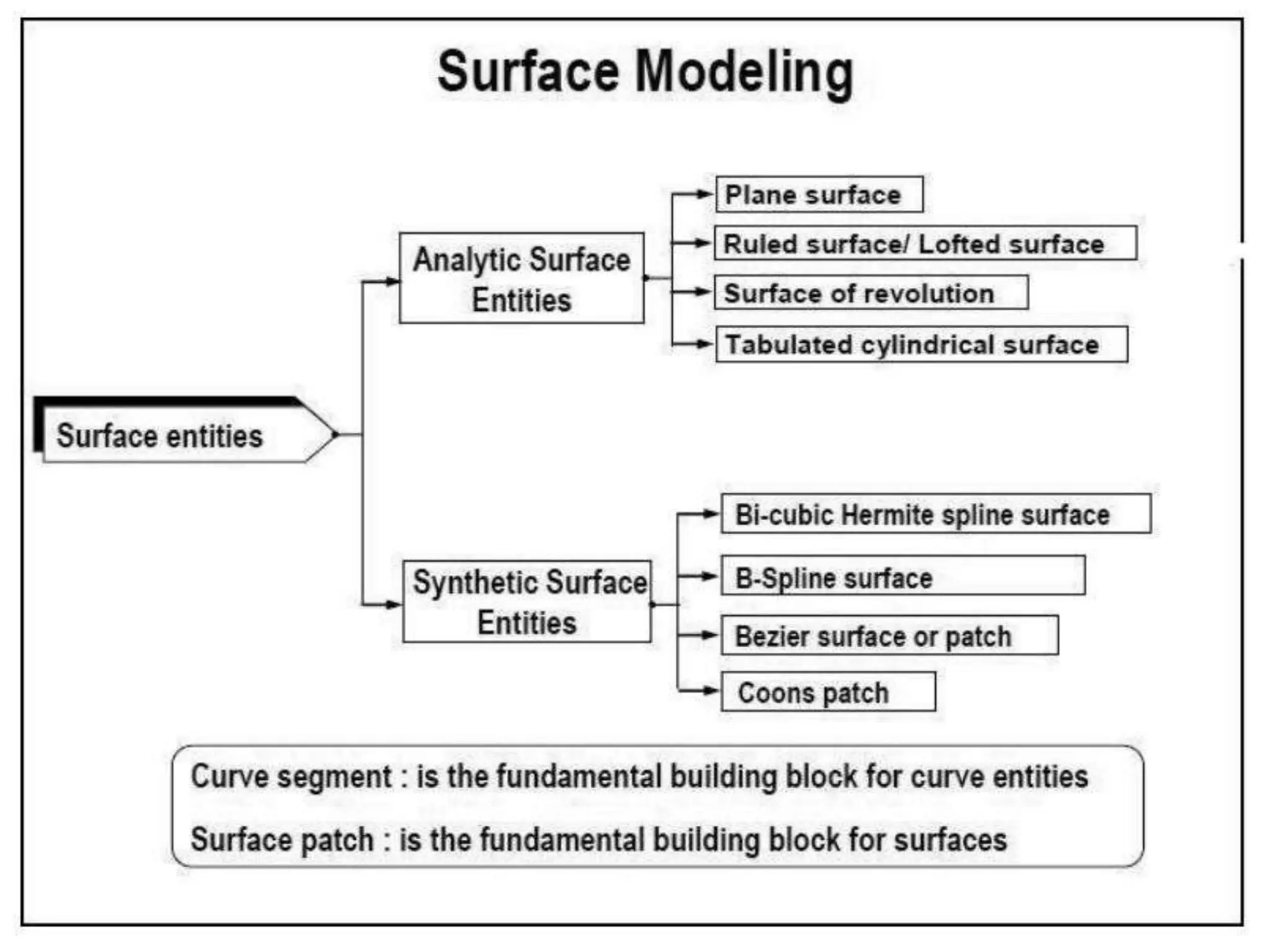
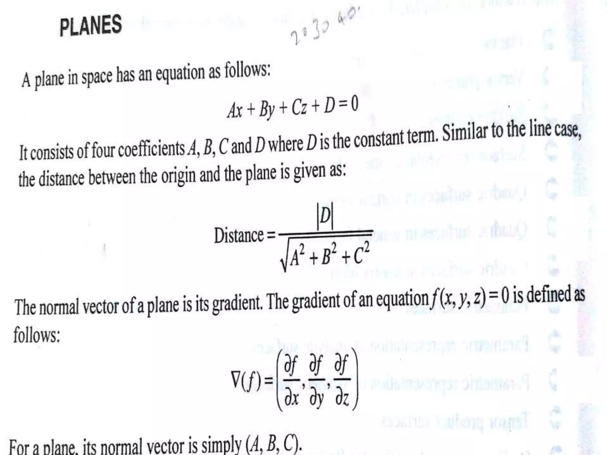
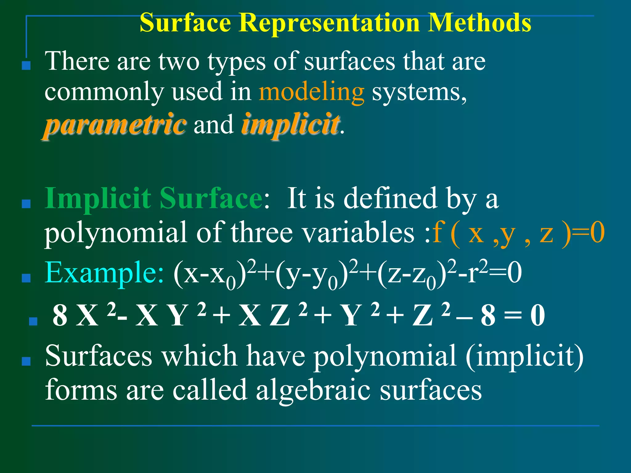
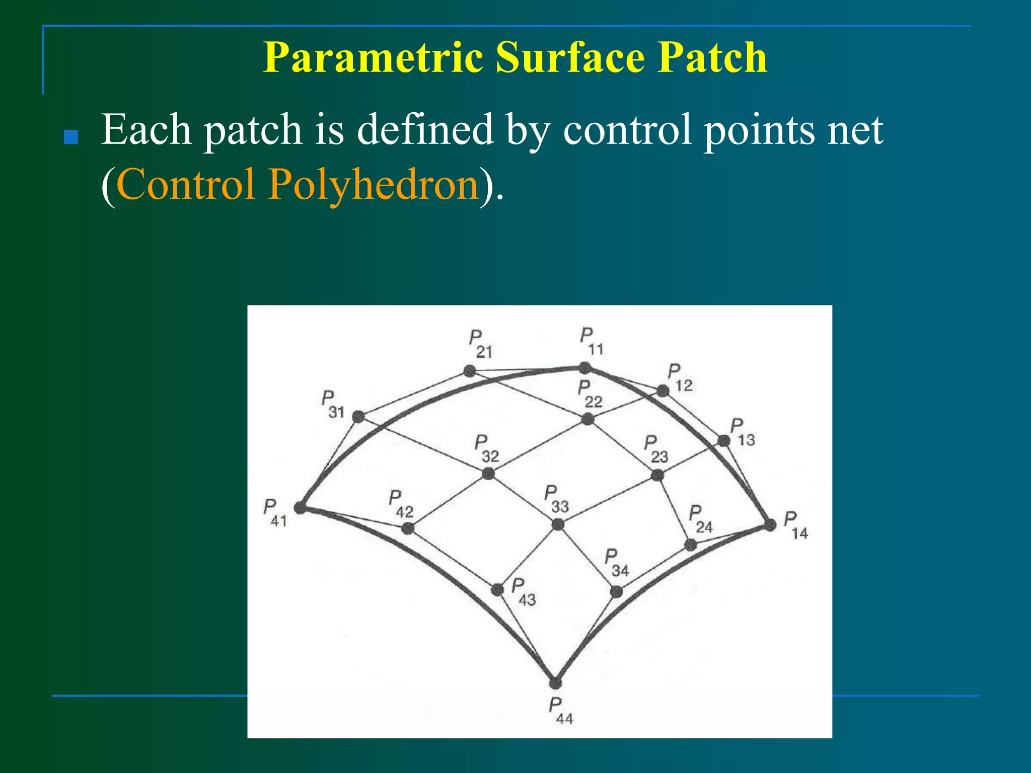
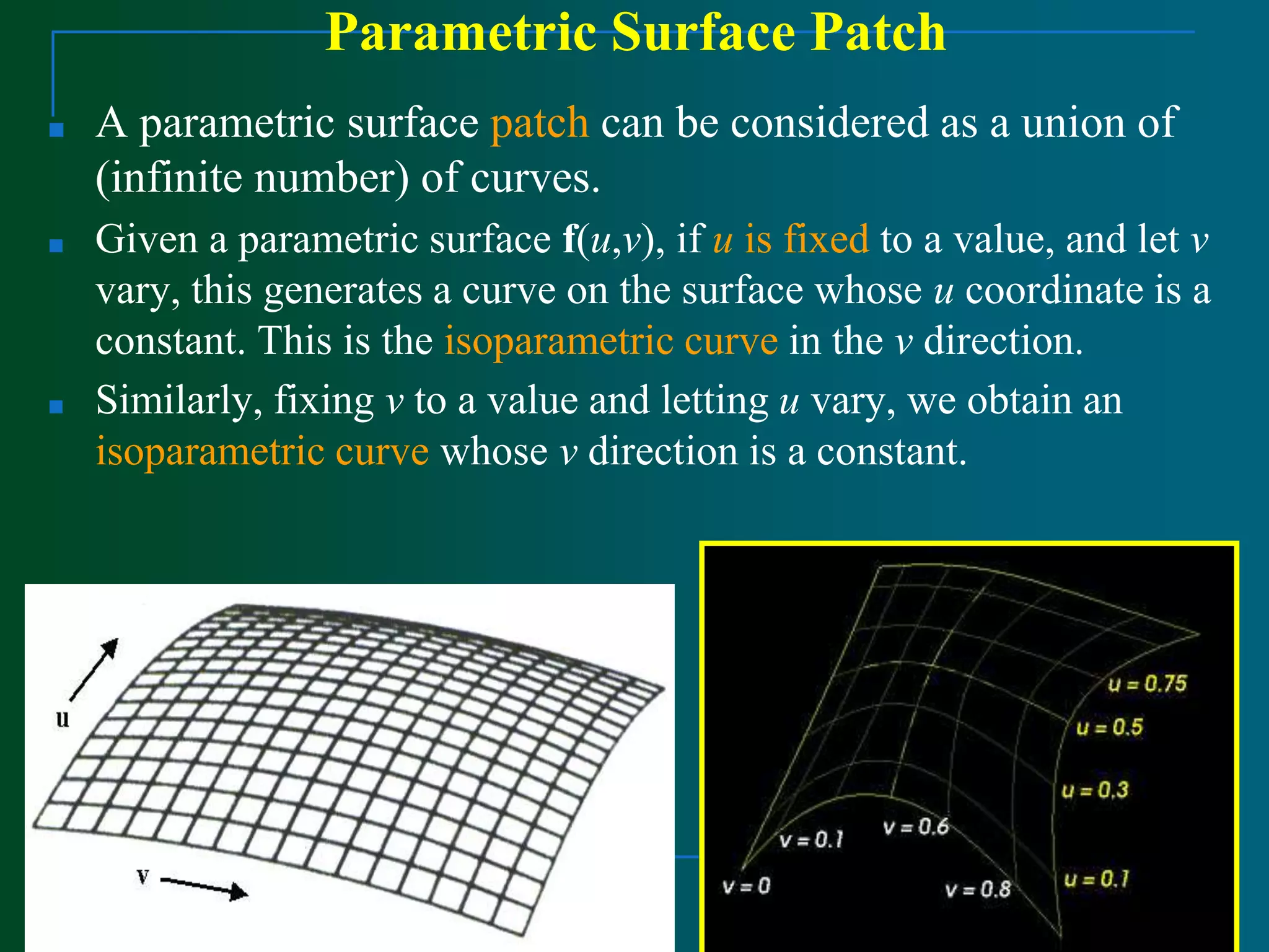
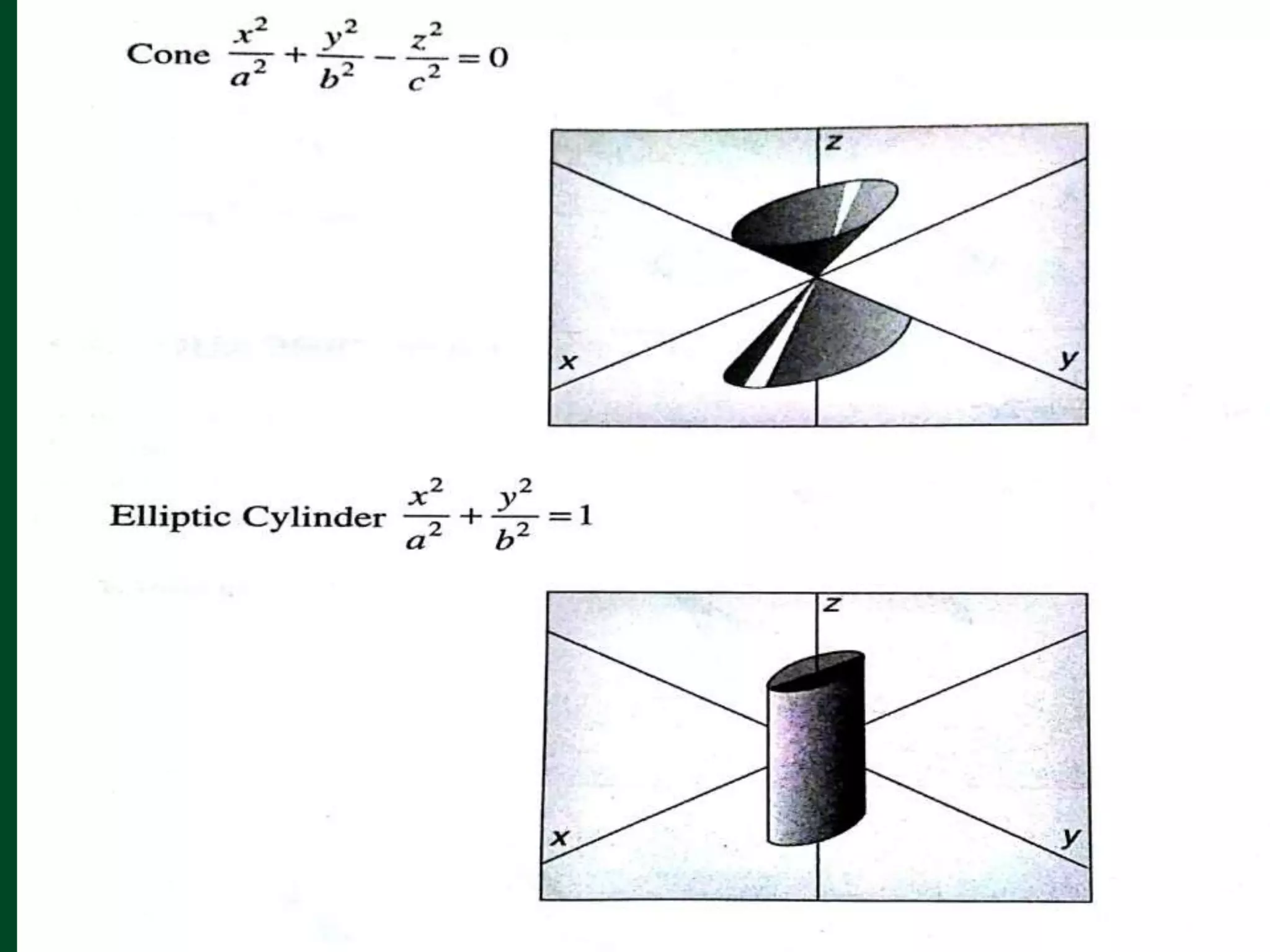
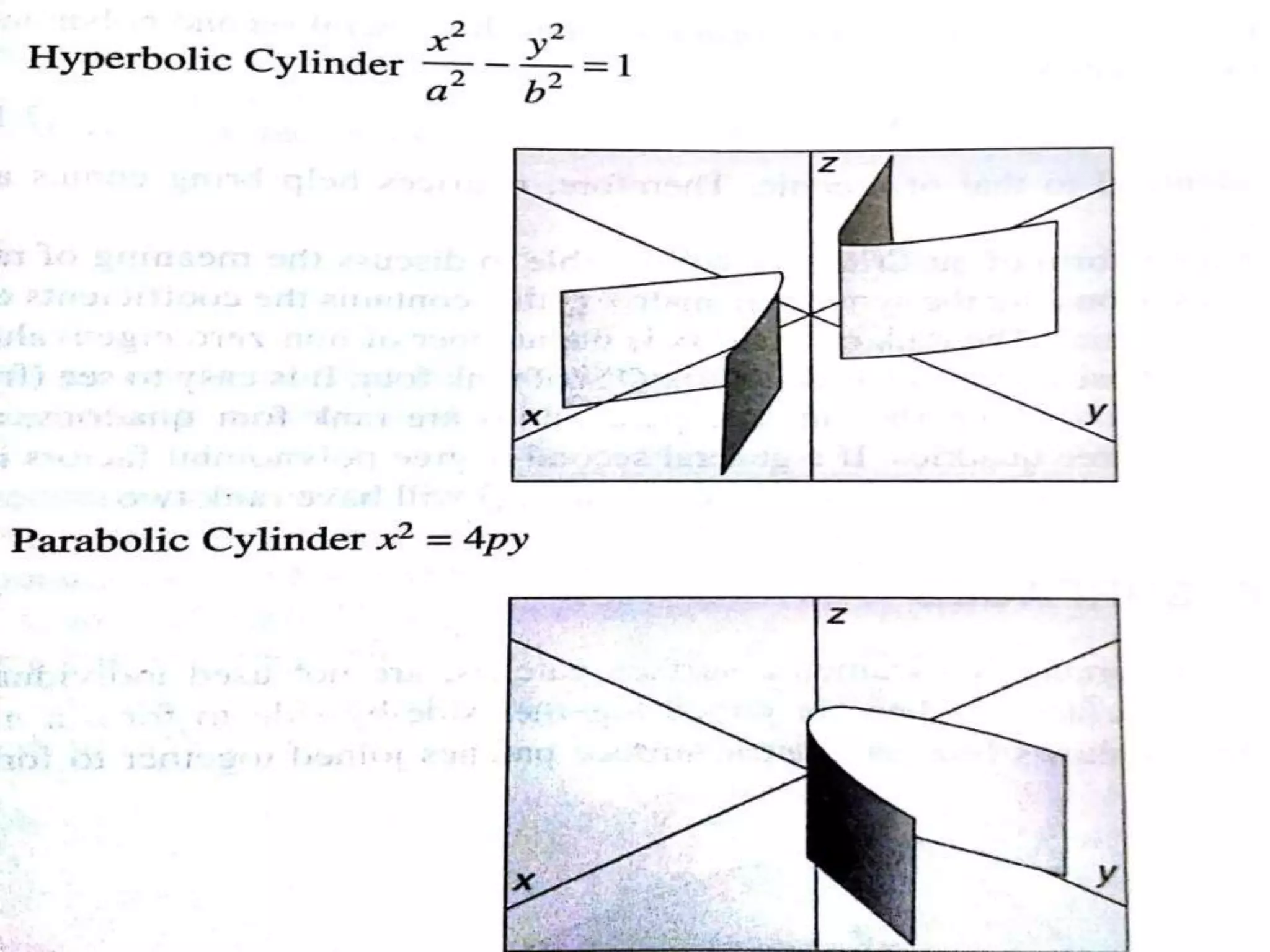
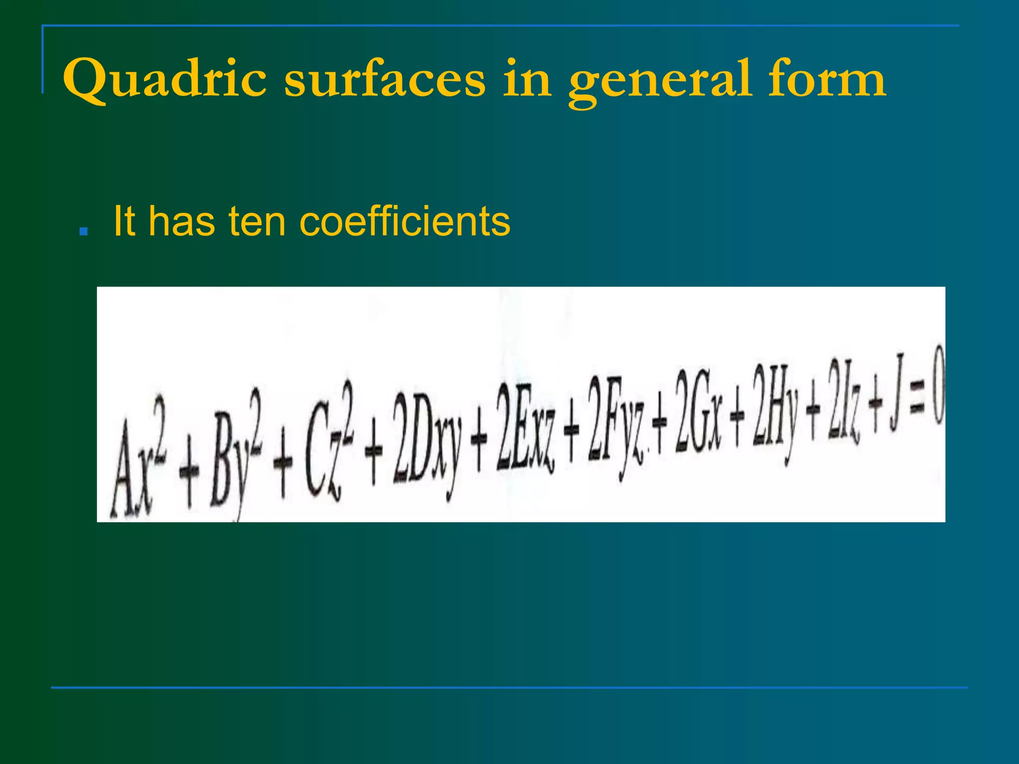
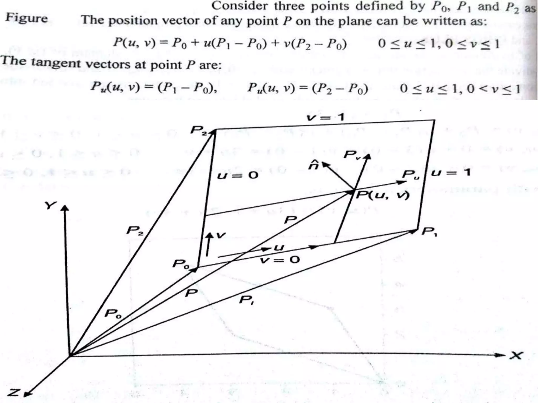
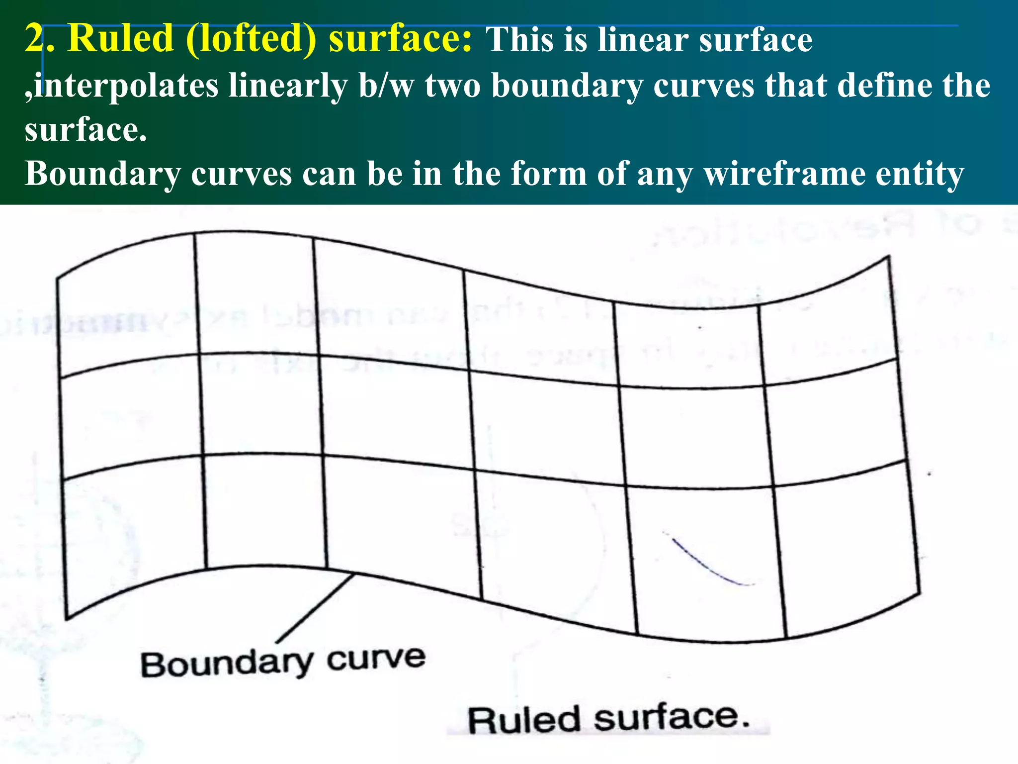
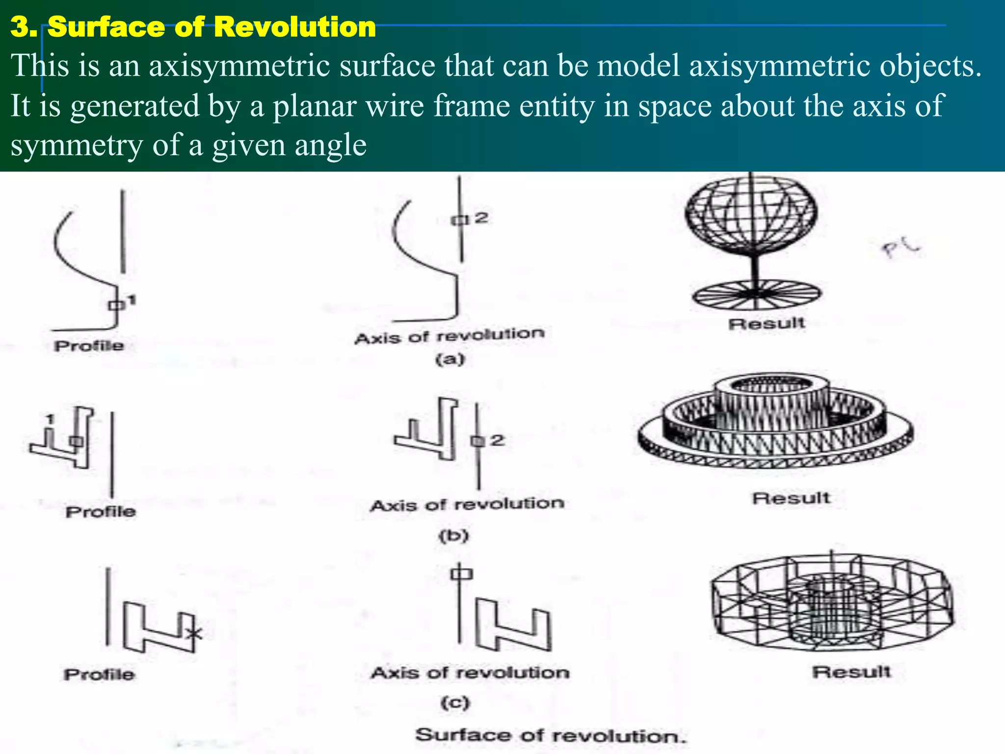
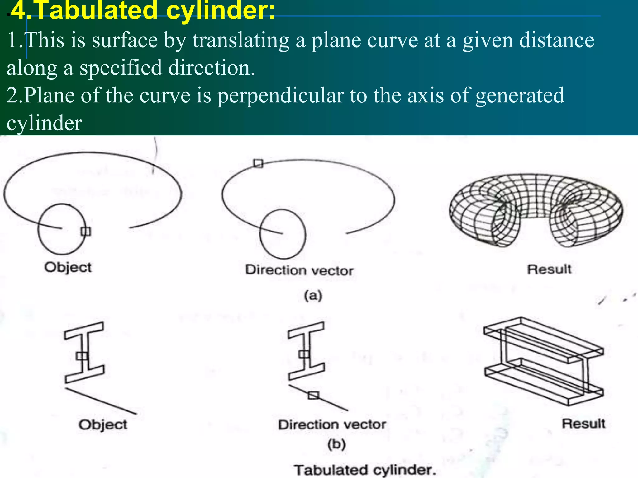
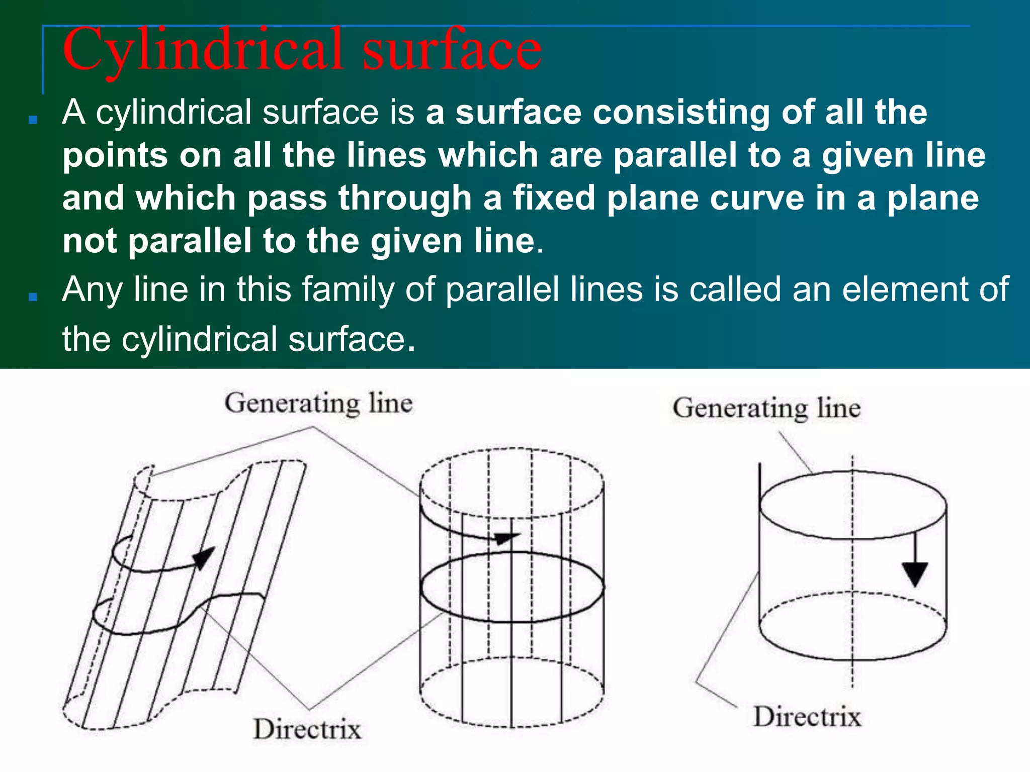
Surface Modelling
Surface Modelling
Parametric Surfaces
1. Wire frame modelling are unable to represent complex
surfaces of objects like car , ship, airplane wing, castings
but surface model can used to represent the surface profile
of these objects
2. surface model can be used for calculating mass properties
, and interference between parts for generating view and
finite elements mesh and NC tool paths for continuous
path machining
3. This model used for fitting experimental data , discretised
solutions of differential equations, construction of pressure
surfaces , construction of stress distribution.
4. This surface of object is a more complete and less
ambiguous than the wire frame modeling
1.Surface modeling is the next stage of wireframe
modeling.
2.In wireframe modeling models are unable to
represent complex surfaces of objects like car,
ship, aeroplane, wings,castings etc. only a surface
profile of these objects.
3.A surface model represents the skin of an object.
4.These skins have no thickness or material type.
5.Surface models define the surface properties, as
well as the edges of objects.
6.These are often capable of clearly representing the
solid from the manufacturing. However, no
information regarding the interior of the solid model
would be available which could be relevant for
generating the NC cutter data.
Advantages:
1. Eliminates much ambiguity and non-uniqueness
present in wireframe models by hiding
lines not seen
2. Renders the model for better visualization and
presentation, objects appear more realistic
3. Provides the surface geometry for CAM, NC machine
4. Provides the geometry needed by the manufacturing
engineer for mould and die design
5. This can be used to design and analysis complex
free-formed surfaces of ship hulls,aeroplane
fuselages and bodies
6. Surface properties such as roughness, color and
reflectivity can be assigned and demonstrated
Disadvantages:
1. Provides no information about the
inside of an object
2. Curved surfaces need a fine mesh to
be accurate
3. Provides wrong results if mesh is too
coarse
4. Complicated computation, depending
on the number of surfaces
Surface Entities
■ 1.Analytic surfaces
Plane , Ruled surfaces, Surface of revolution and
Tabulated cylinder.
■ 2 Synthetic surfaces
Hermite bi- cubic surface , Bezier surface and B –
Spline surface
Surface Representation Methods
■ There are two types of surfaces that are
commonly used in modeling systems,
parametric and implicit.
■ Implicit Surface: It is defined by a
polynomial of three variables :f ( x ,y , z )=0
■ Example: (x-x0)2+(y-y0)2+(z-z0)2-r2=0
■ 8 X 2- X Y 2 + X Z 2 + Y 2 + Z 2 – 8 = 0
■ Surfaces which have polynomial (implicit)
forms are called algebraic surfaces
Parametric Surfaces
■ Parametric surfaces are defined by a set of three functions,
one for each coordinate
x=f(u,v), y=f(u,v), z=f(u,v)
■ Where u and v are in certain domain in the range of 0 and 1 .
■ Thus (u , v ) is a point in the square defined by (0,0)
(1,0) ,(0,1) and (1,1)in the uv – coordinate plane.
■ Parametric surfaces :
f(u,v) = ( x(u,v), y(u,v), z(u,v) )
■ Assume both u and v are in the range of 0 and 1.
Parametric Surfaces
■ Parametric surfaces or more precisely parametric surface
patches are not used individually.
■ Many parametric surface patches are joined together side-by-
side to form a more complicated shape.
Patch
Parametric Surface Patch
■ Each patch is defined by control points net
(Control Polyhedron).
Parametric Surface Patch
■ A parametric surface patch can be considered as a union of
(infinite number) of curves.
■ Given a parametric surface f(u,v), if u is fixed to a value, and let v
vary, this generates a curve on the surface whose u coordinate is a
constant. This is the isoparametric curve in the v direction.
■ Similarly, fixing v to a value and letting u vary, we obtain an
isoparametric curve whose v direction is a constant.
Parametric Surface Patch
■ Point Q(u,v) on the patch is the tensor product
of parametric curves defined by the control
points.
Surface Patch
■ The effect of “lifting” one of he control points of
a patch.
Quadric surfaces in normal forms
Quadric surfaces in general form
■ It has ten coefficients
Parametric representation of Analytic surfaces
1. Plane surface :
■ This is the simplest surface and requires three non –
coincidental points to define an infinite plane
■ The plane surface can be used to generate cross –
sectional views by intersecting a surface with it.
Generate the surface having four sides with parameters u and
v if x+3u + v & y= 2u+uv with boundaries specified as
follows:
2. Ruled (lofted) surface: This is linear surface
,interpolates linearly b/w two boundary curves that define the
surface.
Boundary curves can be in the form of any wireframe entity
3. Surface of Revolution
This is an axisymmetric surface that can be model axisymmetric objects.
It is generated by a planar wire frame entity in space about the axis of
symmetry of a given angle
Line AB is rotated about the z- axis through an angle of 1800
generating cylinder.
Any point on the surface is a function of two parameters U and ɵ
u describes the entity to be rotated and ɵ represent the angle of
rotation .In general form
P(u , v)= r (u) cos ɵ + r(u) sin ɵ + z(u ) n3
•4.Tabulated cylinder:
1.This is surface by translating a plane curve at a given distance
along a specified direction.
2.Plane of the curve is perpendicular to the axis of generated
cylinder
Cylindrical surface
■ A cylindrical surface is a surface consisting of all the
points on all the lines which are parallel to a given line
and which pass through a fixed plane curve in a plane
not parallel to the given line.
■ Any line in this family of parallel lines is called an element of
the cylindrical surface.
SURFACE MODELLING .pptx

SURFACE MODELLING .pptx

  • 1.
  • 2.
    Surface Modelling Parametric Surfaces 1.Wire frame modelling are unable to represent complex surfaces of objects like car , ship, airplane wing, castings but surface model can used to represent the surface profile of these objects 2. surface model can be used for calculating mass properties , and interference between parts for generating view and finite elements mesh and NC tool paths for continuous path machining 3. This model used for fitting experimental data , discretised solutions of differential equations, construction of pressure surfaces , construction of stress distribution. 4. This surface of object is a more complete and less ambiguous than the wire frame modeling
  • 3.
    1.Surface modeling isthe next stage of wireframe modeling. 2.In wireframe modeling models are unable to represent complex surfaces of objects like car, ship, aeroplane, wings,castings etc. only a surface profile of these objects. 3.A surface model represents the skin of an object. 4.These skins have no thickness or material type. 5.Surface models define the surface properties, as well as the edges of objects. 6.These are often capable of clearly representing the solid from the manufacturing. However, no information regarding the interior of the solid model would be available which could be relevant for generating the NC cutter data.
  • 4.
    Advantages: 1. Eliminates muchambiguity and non-uniqueness present in wireframe models by hiding lines not seen 2. Renders the model for better visualization and presentation, objects appear more realistic 3. Provides the surface geometry for CAM, NC machine 4. Provides the geometry needed by the manufacturing engineer for mould and die design 5. This can be used to design and analysis complex free-formed surfaces of ship hulls,aeroplane fuselages and bodies 6. Surface properties such as roughness, color and reflectivity can be assigned and demonstrated
  • 5.
    Disadvantages: 1. Provides noinformation about the inside of an object 2. Curved surfaces need a fine mesh to be accurate 3. Provides wrong results if mesh is too coarse 4. Complicated computation, depending on the number of surfaces
  • 9.
    Surface Entities ■ 1.Analyticsurfaces Plane , Ruled surfaces, Surface of revolution and Tabulated cylinder. ■ 2 Synthetic surfaces Hermite bi- cubic surface , Bezier surface and B – Spline surface
  • 10.
    Surface Representation Methods ■There are two types of surfaces that are commonly used in modeling systems, parametric and implicit. ■ Implicit Surface: It is defined by a polynomial of three variables :f ( x ,y , z )=0 ■ Example: (x-x0)2+(y-y0)2+(z-z0)2-r2=0 ■ 8 X 2- X Y 2 + X Z 2 + Y 2 + Z 2 – 8 = 0 ■ Surfaces which have polynomial (implicit) forms are called algebraic surfaces
  • 11.
    Parametric Surfaces ■ Parametricsurfaces are defined by a set of three functions, one for each coordinate x=f(u,v), y=f(u,v), z=f(u,v) ■ Where u and v are in certain domain in the range of 0 and 1 . ■ Thus (u , v ) is a point in the square defined by (0,0) (1,0) ,(0,1) and (1,1)in the uv – coordinate plane.
  • 12.
    ■ Parametric surfaces: f(u,v) = ( x(u,v), y(u,v), z(u,v) ) ■ Assume both u and v are in the range of 0 and 1.
  • 13.
    Parametric Surfaces ■ Parametricsurfaces or more precisely parametric surface patches are not used individually. ■ Many parametric surface patches are joined together side-by- side to form a more complicated shape. Patch
  • 14.
    Parametric Surface Patch ■Each patch is defined by control points net (Control Polyhedron).
  • 15.
    Parametric Surface Patch ■A parametric surface patch can be considered as a union of (infinite number) of curves. ■ Given a parametric surface f(u,v), if u is fixed to a value, and let v vary, this generates a curve on the surface whose u coordinate is a constant. This is the isoparametric curve in the v direction. ■ Similarly, fixing v to a value and letting u vary, we obtain an isoparametric curve whose v direction is a constant.
  • 16.
    Parametric Surface Patch ■Point Q(u,v) on the patch is the tensor product of parametric curves defined by the control points.
  • 17.
    Surface Patch ■ Theeffect of “lifting” one of he control points of a patch.
  • 18.
    Quadric surfaces innormal forms
  • 23.
    Quadric surfaces ingeneral form ■ It has ten coefficients
  • 24.
    Parametric representation ofAnalytic surfaces 1. Plane surface : ■ This is the simplest surface and requires three non – coincidental points to define an infinite plane ■ The plane surface can be used to generate cross – sectional views by intersecting a surface with it.
  • 27.
    Generate the surfacehaving four sides with parameters u and v if x+3u + v & y= 2u+uv with boundaries specified as follows:
  • 29.
    2. Ruled (lofted)surface: This is linear surface ,interpolates linearly b/w two boundary curves that define the surface. Boundary curves can be in the form of any wireframe entity
  • 31.
    3. Surface ofRevolution This is an axisymmetric surface that can be model axisymmetric objects. It is generated by a planar wire frame entity in space about the axis of symmetry of a given angle
  • 32.
    Line AB isrotated about the z- axis through an angle of 1800 generating cylinder. Any point on the surface is a function of two parameters U and ɵ u describes the entity to be rotated and ɵ represent the angle of rotation .In general form P(u , v)= r (u) cos ɵ + r(u) sin ɵ + z(u ) n3
  • 33.
    •4.Tabulated cylinder: 1.This issurface by translating a plane curve at a given distance along a specified direction. 2.Plane of the curve is perpendicular to the axis of generated cylinder
  • 35.
    Cylindrical surface ■ Acylindrical surface is a surface consisting of all the points on all the lines which are parallel to a given line and which pass through a fixed plane curve in a plane not parallel to the given line. ■ Any line in this family of parallel lines is called an element of the cylindrical surface.