The document covers geometric modeling in mechanical engineering, detailing various techniques such as Hermite curves, Bezier curves, B-spline curves, and solid modeling methods like constructive solid geometry (CSG) and boundary representation (B-rep). It explains the properties and applications of each type of curve and surface used in modeling, emphasizing the advantages of 3D models for simulations, presentations, and manufacturing. Additionally, it discusses the validity and construction methods of solid models, highlighting the differences between CSG and B-rep approaches.


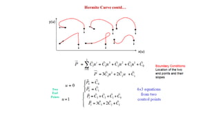

![Hermite Curve contd…
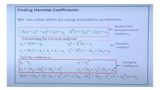
where [MH] is the Hermite matrix and V is the geometry (or boundary conditions)
vector.](https://image.slidesharecdn.com/cadmunit2-210216104659/85/UNIT-2-GEOMETRIC-MODELLING-27-320.jpg)