Download to read offline


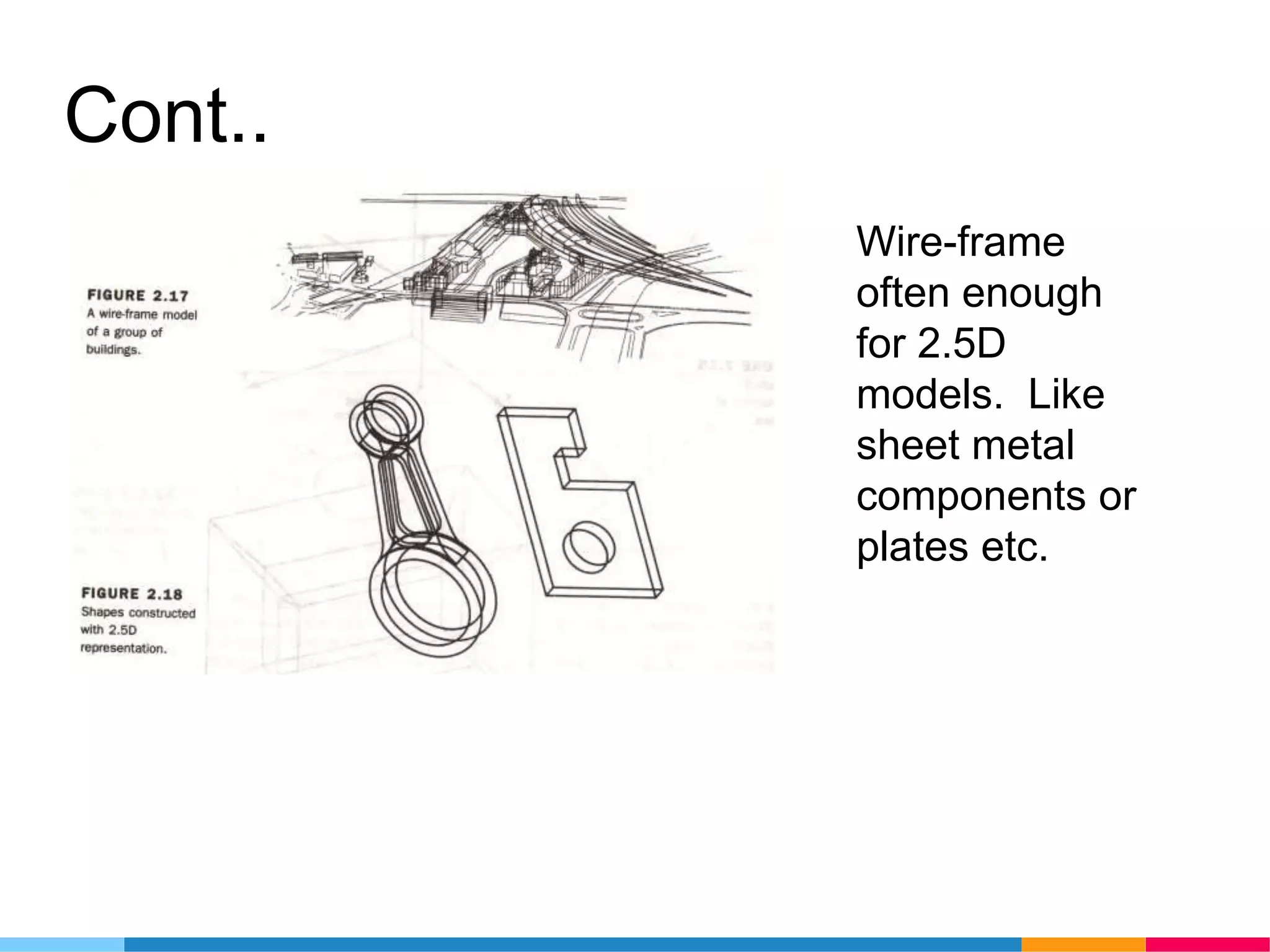
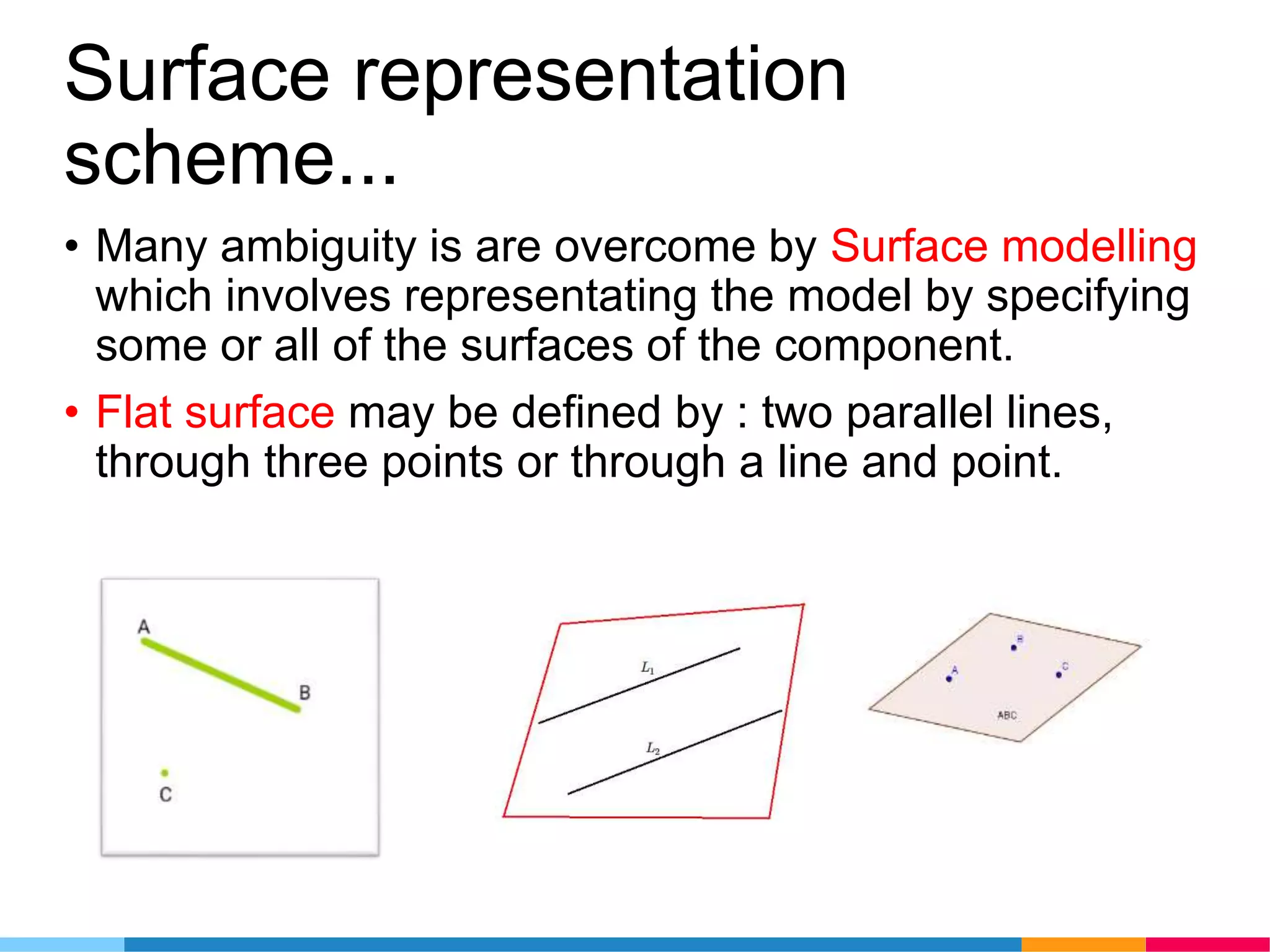
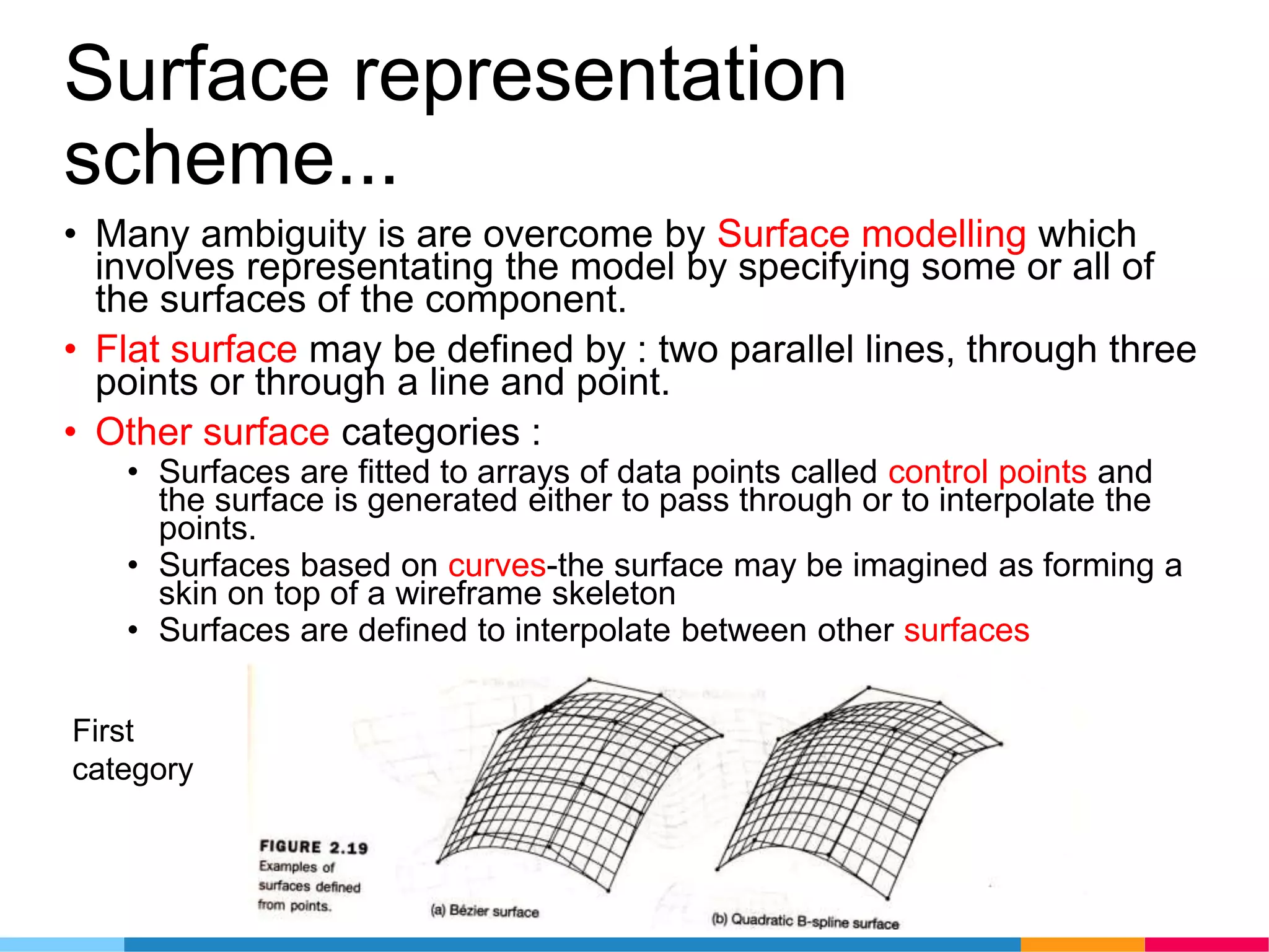
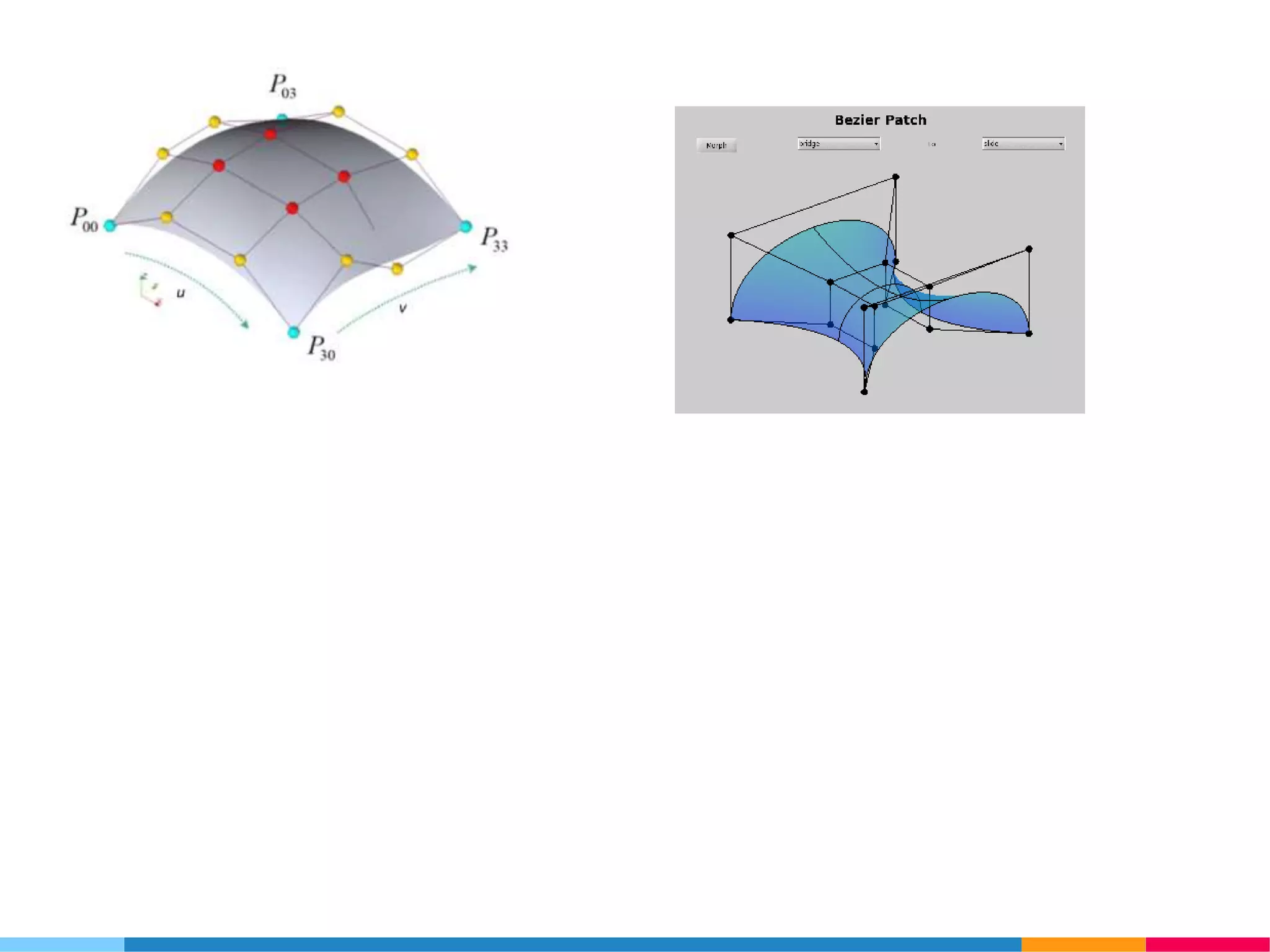
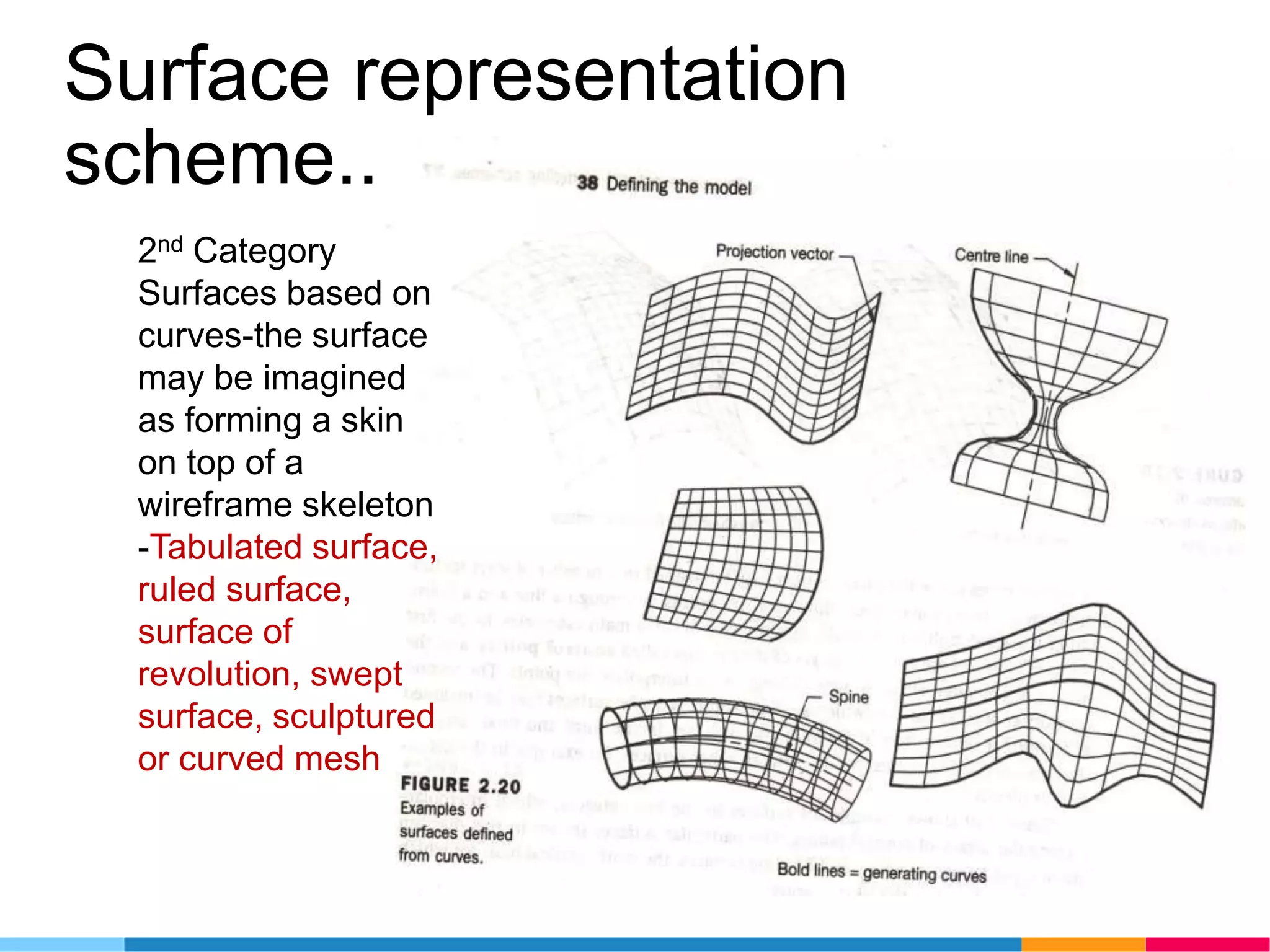

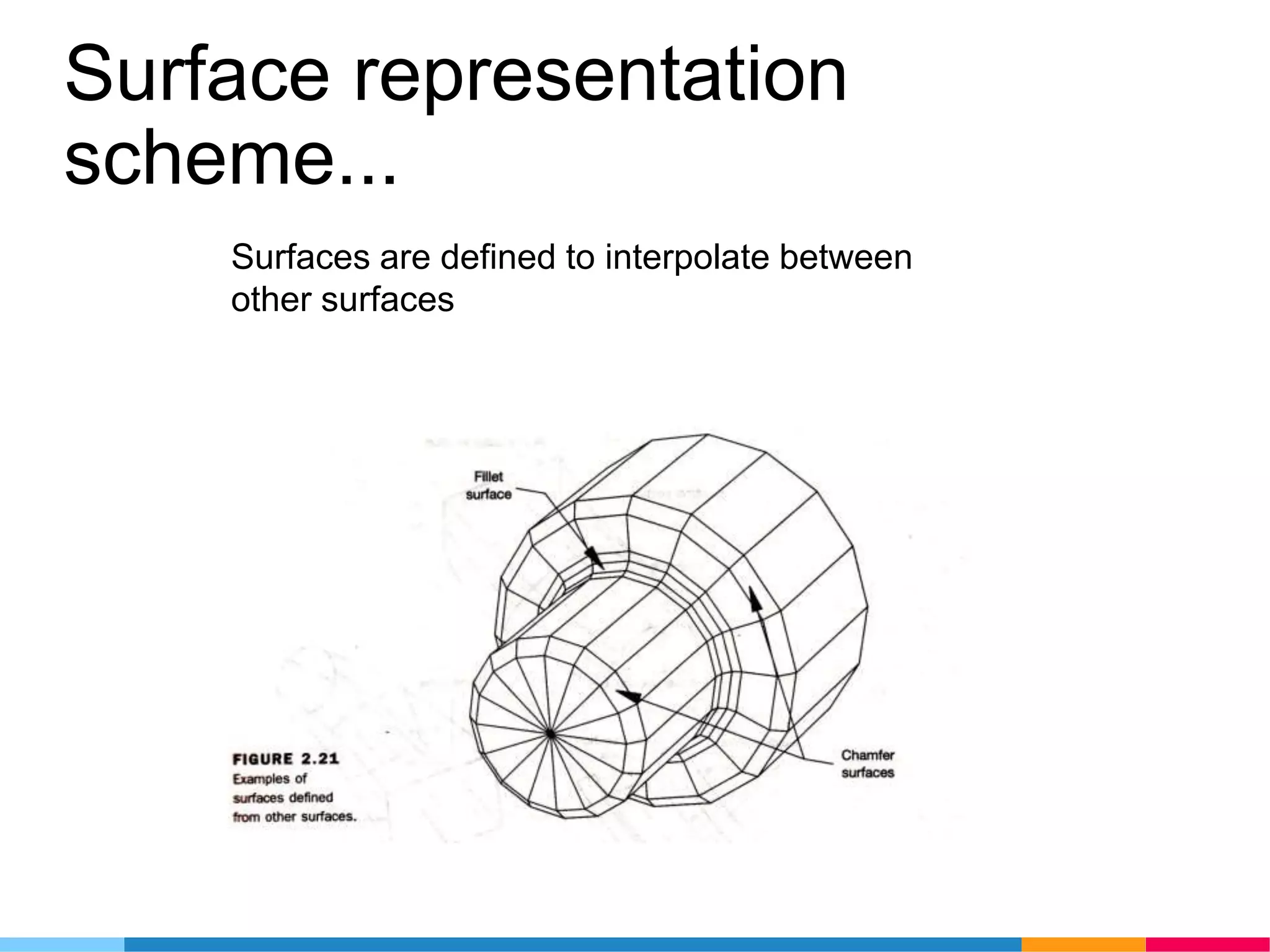

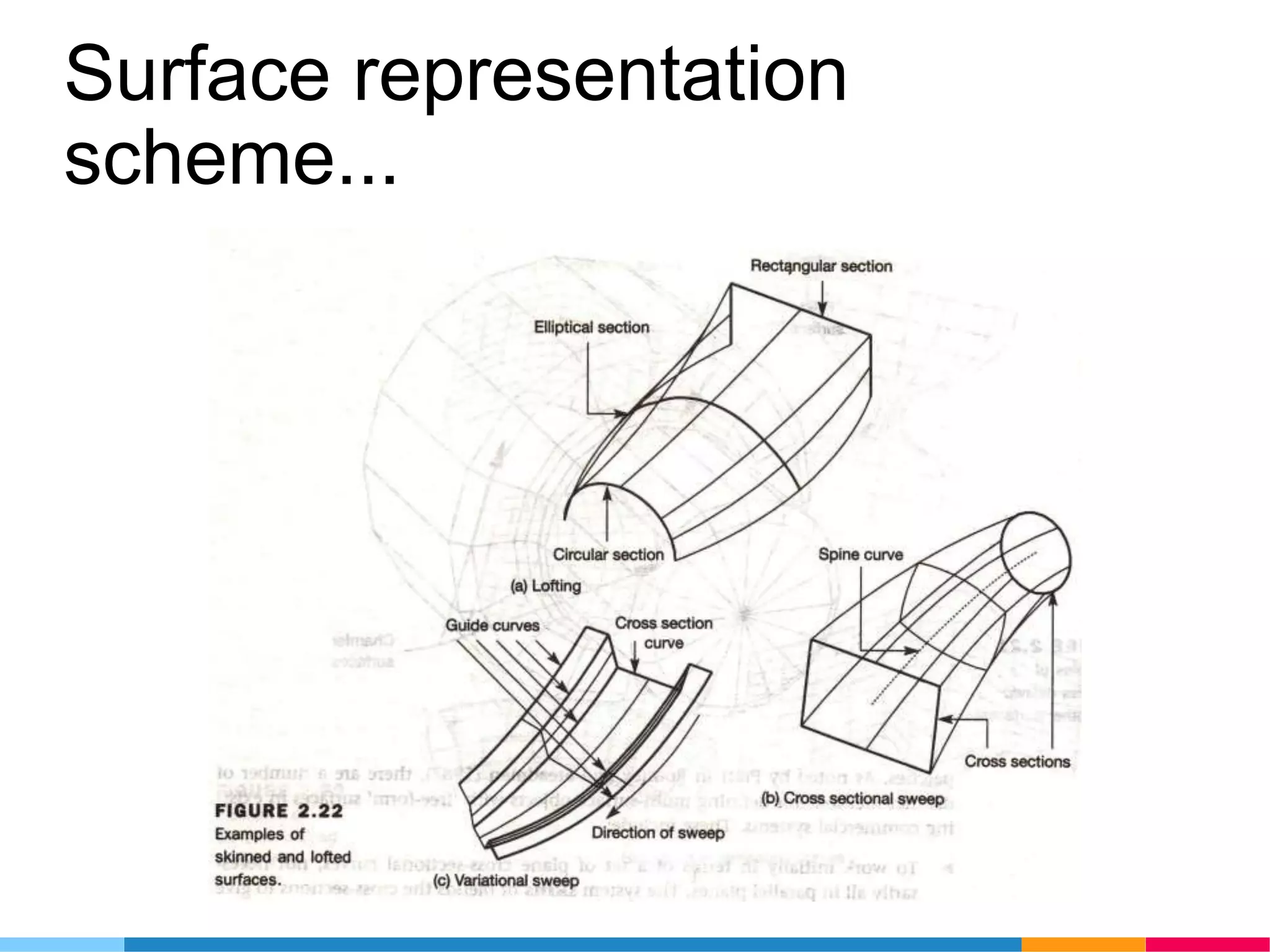


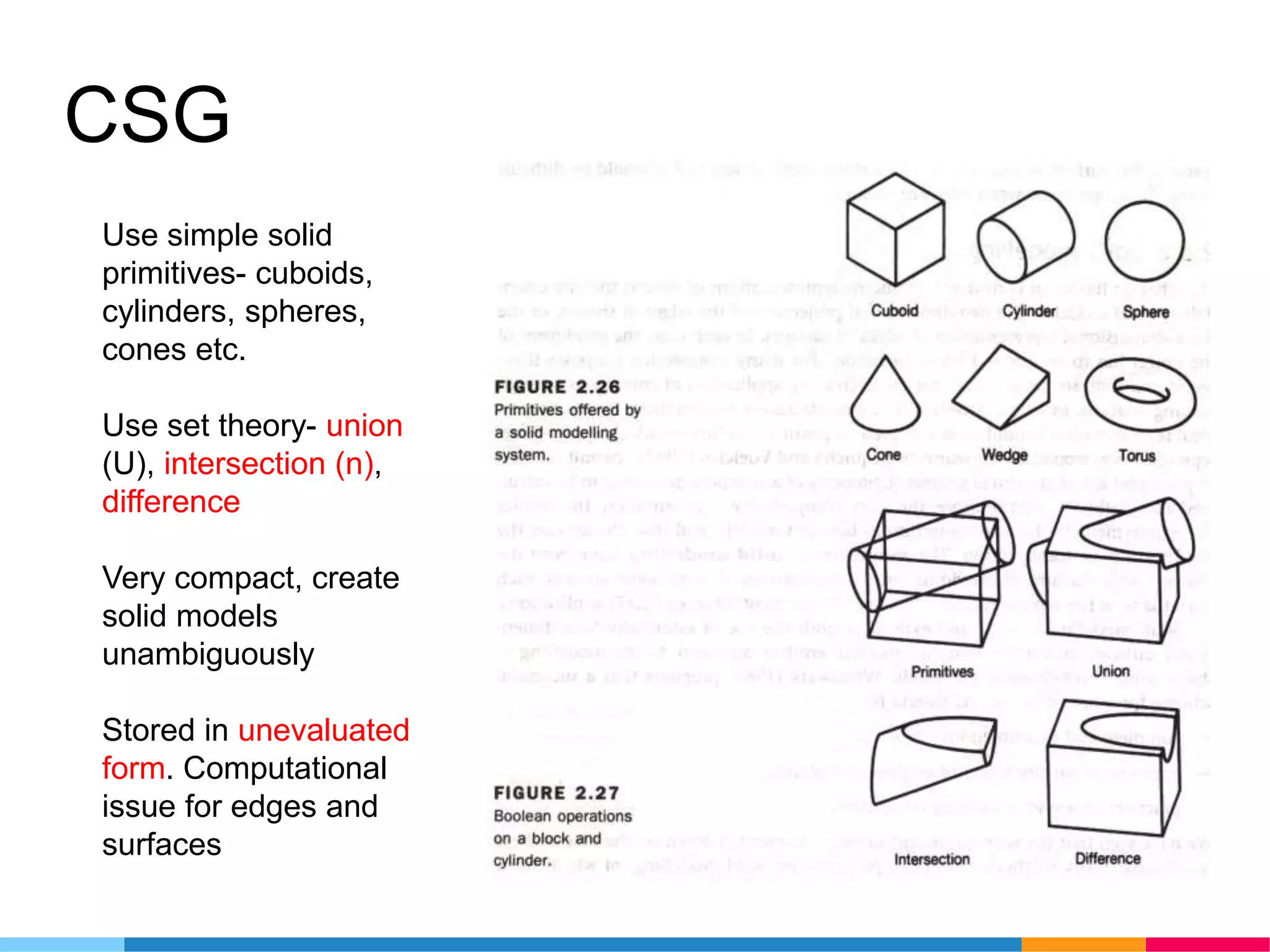


This document discusses different methods for representing 3D models, including: - Traditional representations using engineering drawings had weaknesses like ambiguity. - Computer representations include wireframe geometry, surface representations using tabulated, ruled or swept surfaces, and solid modeling using constructive solid geometry (CSG) or boundary representation (B-rep). - Surface modeling overcomes some ambiguities of wireframes by specifying surfaces, but is computationally demanding. - Solid modeling with CSG uses primitives and boolean operations, while B-rep ensures topological consistency of faces, edges and vertices. - B-rep is more popular than CSG due to limitations of CSG for displays and easier conversion from CSG to