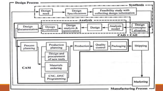
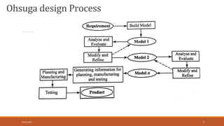
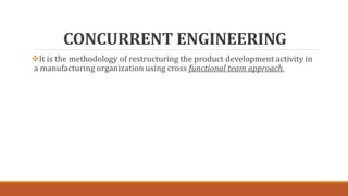
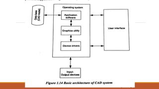
COMPUTER AIDED DESIGN AND
MANUFACTURING
UNIT 1
INTRODUCTION
SYALLABUS
Product cycle, Design process, Sequential and concurrent engineering
Computer aided design – CAD system architecture, Computer graphics
co-ordinate systems- 2D and 3D transformations – homogeneous coordinates
Line drawing -Clipping- viewing transformation
Brief introduction to CAD and CAM – Manufacturing Planning
Manufacturing control- Introduction to CAD/CAM –CAD/CAM concepts
Types of production - Manufacturing models and Metrics
Mathematical models of Production Performance
Product cycle
The cycle through which a product goes from development to
retirement is called product life cycle.
The product cycle starts with developing the product concept,
evolving the design, engineering the product, manufacturing the
part, marketing and servicing.
The product undergoes the following two main processes
Design process
Manufacturing process
DESIGN PROCESS
Design is an activity that needs to be well organized and should take into
account all influences that are likely to be responsible for the success of the
product under development.
The following models are considered in design purpose
Shigley
Pahl and Beitz
Ohsuga
Earle
Shigley design Process
28-03-2020 7
Pahl and Beitz design
Process
28-03-2020 8
Ohsuga design Process
28-03-2020 9
Earle design Process
28-03-2020 10
SEQUENCIAL ENGINEERING
Three major phases of conventional manufacturing process are design,
process planning and manufacturing.
All these phases are sequentially carried out.
CONCURRENT ENGINEERING
It is the methodology of restructuring the product development activity in
a manufacturing organization using cross functional team approach.
COMPARISION BETWEEN SEQUENTIAL
AND CONCURRENT ENGINEERING
Product development cost
Number of design changes
Lead time for product development
Customer satisfaction
Coordination between departments
COMPUTER AIDED DESIGN
Groover and Zimmers defined “CAD is the technology concerned with the use
of computer systems to assist the creation, modification, analysis and
optimization of a design”.
Roles of CAD in Design
Accurately generated and easily modifiable graphical representation of the
product.
User can nearly view the actual product on the screen, make any
modification to it and present his ideas on screen without any prototype,
especially during the early stages of the design process.
Complex design analysis in short time. By implementing Finite Element
Analysis (FEA) methods user can perform as follows
Static, dynamic & natural frequency analysis
Heat transfer analysis
Fluid flow analysis
Plastic analysis
Roles of CAD in Design
It records and recalls information with consistency and speed
Use of Product Data Management (PDM) systems can store the whole
design and processing history of a certain product for future reuse and
upgrade.
CAD PROCESS
APPLICATION OF CAD
Mechanical engineering
Civil engineering
Electrical and electronics engineering
Textile industry
ADVANTAGES OF CAD
Easy editing
High quality
Compact storage
3D Drawing
CAD SYSTEM ARCHITECTURE
It is an early model which was used for the basic geometry construction
and modelling purpose.
Four major components of CAD System Architecture are
1. Database
2. Operating system
3. Input/output devices
4. User interface
COMPUTER GRAPHICS (CG)
Computer graphics is a technology which uses the display of the drawing or
the geometric model of the component in CAD.
CG may be defined as the process of creation, storage and manipulation of
drawings and pictures with aid of a computer.
It is an extremely effective medium for communication between users and
computers.
There are two types
1. Passive CG
2. Interactive CG
Interactive CG
The following functions of the ICG
Modelling
Storage
Manipulation
Viewing
ADVANTAGES OF COMPUTER
GRAPHICS
The object drawings can be denoted by its geometric model in three
dimensions. i.e. X, Y, Z coordinates.
Accurate drawings can be made.
Sectional drawings can be easily created.
Modification of geometric model of objects is easy.
It is easy storage and retrieval of drawings.
APPLICATIONS OF COMPUTER
GRAPHICS
Paint programs
Design programs
Presentation graphics software
Animation software
CAD software
Desktop publishing
Education and training
Image processing
CO-ORDINATE SYSTEMS
In general, there are two types of co-ordinate system
1. Cartesian – Linear distances X,Y and Z
2. Polar – Angles such as θ, α, φ
Left hand and right hand co-ordinate systems
Multiple co-ordinate systems
World co-ordinate system
Object co-ordinate system
Hierarchical co-ordinate system
View point co-ordinate system
Model view co-ordinate system
Screen co-ordinate system
View port co-ordinate system
Left and right handed
coordinate system
28-03-2020 34
2D & 3D
(GEOMETRIC)TRANSFORMATION
A geometric transformation is an operation that modifies
its shape, size, position, orientation etc. with respect to its
current configuration operating on the vertices.
Some of the important transformations are
Translation
Scaling
Rotation
Reflection
Shear
28-03-2020 35
2D & 3D TRASLATION
,
, ,
.
    
     
            
 
x y
x
y
x x t y y t
tx x
ty y
P P T
P P T
28-03-2020
36
2D FORMULA 3D FORMULA
2D & 3D SCALING
28-03-2020
38
2D FORMULA 3D FORMULA
,
0
0
x y
x
y
x x s y y s
sx x
sy y
    
     
         
  P S P
2D & 3D ROTATION
28-03-2020
40
2D FORMULA 3D FORMULA
CONCATENATION OR COMBINED
TRANSFORMATION
HOMOGENEOUS TRANSFORMATION
The three dimensional representation of two
dimensional plane is called as homogeneous
representation and the transformation using
homogeneous representation is called
homogeneous transformation.
28-03-2020 43
HOMOGENEOUS TRANSFORMATION
28-03-2020 44
LINE DRAWING
28-03-2020 46
Straight line segments are used a great deal in computer generated
pictures. The following criteria have been stipulated for line drawing
displays:
i. Lines should appear straight
ii.Lines should terminate accurately
iii.Lines should have constant density
iv.Line density should be independent of length and angle
v.Line should be drawn rapidly
DDA ALGORITHM
28-03-2020 47
A popular method uses an algorithm known as “Digital Differential
Analyzer” which generates lines from their differential equations.
For a line segment joining two points P1 and P2, a parametric
representation is given by
P(u) =P1+(P2-P1)u
In terms of x(u) and y(u)
x(u) = x1 + (x2-x1)u
y(u) = y1 + (y2-y1)u
BRESENHAM’S LINE ALGORITHM
28-03-2020 48
The basic principle of Bresenham’s line algorithms is to select the optimum
raster location to represents a straight line.
To achieve optimum raster scan, the algorithm always increments either x
or y by one unit depending on the slope line.
The increment in the other variable is determined by examining the
distance between the actual line location and the nearest pixel.
This distance is called decision variable or error.
CLIPPING
28-03-2020 49
If any part of the geometry is not inside the window, it is made invisible by
the graphic software is called clipping.
28-03-2020 50
28-03-2020 51
VIEWING TRANSFORMATIONS
28-03-2020 52
Displaying an image of a picture involves in mapping the co-ordinates of the
picture into the appropriate coordinates on the device where the image is to
be displayed.
28-03-2020 53

Unit 1-ME8691 & COMPUTER AIDED DESIGN AND MANUFACTURING

  • 1.
    COMPUTER AIDED DESIGNAND MANUFACTURING
  • 2.
  • 3.
    SYALLABUS Product cycle, Designprocess, Sequential and concurrent engineering Computer aided design – CAD system architecture, Computer graphics co-ordinate systems- 2D and 3D transformations – homogeneous coordinates Line drawing -Clipping- viewing transformation Brief introduction to CAD and CAM – Manufacturing Planning Manufacturing control- Introduction to CAD/CAM –CAD/CAM concepts Types of production - Manufacturing models and Metrics Mathematical models of Production Performance
  • 4.
    Product cycle The cyclethrough which a product goes from development to retirement is called product life cycle. The product cycle starts with developing the product concept, evolving the design, engineering the product, manufacturing the part, marketing and servicing. The product undergoes the following two main processes Design process Manufacturing process
  • 6.
    DESIGN PROCESS Design isan activity that needs to be well organized and should take into account all influences that are likely to be responsible for the success of the product under development. The following models are considered in design purpose Shigley Pahl and Beitz Ohsuga Earle
  • 7.
  • 8.
    Pahl and Beitzdesign Process 28-03-2020 8
  • 9.
  • 10.
  • 11.
    SEQUENCIAL ENGINEERING Three majorphases of conventional manufacturing process are design, process planning and manufacturing. All these phases are sequentially carried out.
  • 13.
    CONCURRENT ENGINEERING It isthe methodology of restructuring the product development activity in a manufacturing organization using cross functional team approach.
  • 15.
    COMPARISION BETWEEN SEQUENTIAL ANDCONCURRENT ENGINEERING Product development cost Number of design changes Lead time for product development Customer satisfaction Coordination between departments
  • 18.
    COMPUTER AIDED DESIGN Grooverand Zimmers defined “CAD is the technology concerned with the use of computer systems to assist the creation, modification, analysis and optimization of a design”.
  • 19.
    Roles of CADin Design Accurately generated and easily modifiable graphical representation of the product. User can nearly view the actual product on the screen, make any modification to it and present his ideas on screen without any prototype, especially during the early stages of the design process. Complex design analysis in short time. By implementing Finite Element Analysis (FEA) methods user can perform as follows Static, dynamic & natural frequency analysis Heat transfer analysis Fluid flow analysis Plastic analysis
  • 20.
    Roles of CADin Design It records and recalls information with consistency and speed Use of Product Data Management (PDM) systems can store the whole design and processing history of a certain product for future reuse and upgrade.
  • 21.
  • 22.
    APPLICATION OF CAD Mechanicalengineering Civil engineering Electrical and electronics engineering Textile industry
  • 23.
    ADVANTAGES OF CAD Easyediting High quality Compact storage 3D Drawing
  • 24.
    CAD SYSTEM ARCHITECTURE Itis an early model which was used for the basic geometry construction and modelling purpose. Four major components of CAD System Architecture are 1. Database 2. Operating system 3. Input/output devices 4. User interface
  • 27.
    COMPUTER GRAPHICS (CG) Computergraphics is a technology which uses the display of the drawing or the geometric model of the component in CAD. CG may be defined as the process of creation, storage and manipulation of drawings and pictures with aid of a computer. It is an extremely effective medium for communication between users and computers. There are two types 1. Passive CG 2. Interactive CG
  • 29.
    Interactive CG The followingfunctions of the ICG Modelling Storage Manipulation Viewing
  • 30.
    ADVANTAGES OF COMPUTER GRAPHICS Theobject drawings can be denoted by its geometric model in three dimensions. i.e. X, Y, Z coordinates. Accurate drawings can be made. Sectional drawings can be easily created. Modification of geometric model of objects is easy. It is easy storage and retrieval of drawings.
  • 31.
    APPLICATIONS OF COMPUTER GRAPHICS Paintprograms Design programs Presentation graphics software Animation software CAD software Desktop publishing Education and training Image processing
  • 32.
    CO-ORDINATE SYSTEMS In general,there are two types of co-ordinate system 1. Cartesian – Linear distances X,Y and Z 2. Polar – Angles such as θ, α, φ
  • 33.
    Left hand andright hand co-ordinate systems Multiple co-ordinate systems World co-ordinate system Object co-ordinate system Hierarchical co-ordinate system View point co-ordinate system Model view co-ordinate system Screen co-ordinate system View port co-ordinate system
  • 34.
    Left and righthanded coordinate system 28-03-2020 34
  • 35.
    2D & 3D (GEOMETRIC)TRANSFORMATION Ageometric transformation is an operation that modifies its shape, size, position, orientation etc. with respect to its current configuration operating on the vertices. Some of the important transformations are Translation Scaling Rotation Reflection Shear 28-03-2020 35
  • 36.
    2D & 3DTRASLATION , , , .                           x y x y x x t y y t tx x ty y P P T P P T 28-03-2020 36 2D FORMULA 3D FORMULA
  • 38.
    2D & 3DSCALING 28-03-2020 38 2D FORMULA 3D FORMULA , 0 0 x y x y x x s y y s sx x sy y                        P S P
  • 40.
    2D & 3DROTATION 28-03-2020 40 2D FORMULA 3D FORMULA
  • 42.
  • 43.
    HOMOGENEOUS TRANSFORMATION The threedimensional representation of two dimensional plane is called as homogeneous representation and the transformation using homogeneous representation is called homogeneous transformation. 28-03-2020 43
  • 44.
  • 46.
    LINE DRAWING 28-03-2020 46 Straightline segments are used a great deal in computer generated pictures. The following criteria have been stipulated for line drawing displays: i. Lines should appear straight ii.Lines should terminate accurately iii.Lines should have constant density iv.Line density should be independent of length and angle v.Line should be drawn rapidly
  • 47.
    DDA ALGORITHM 28-03-2020 47 Apopular method uses an algorithm known as “Digital Differential Analyzer” which generates lines from their differential equations. For a line segment joining two points P1 and P2, a parametric representation is given by P(u) =P1+(P2-P1)u In terms of x(u) and y(u) x(u) = x1 + (x2-x1)u y(u) = y1 + (y2-y1)u
  • 48.
    BRESENHAM’S LINE ALGORITHM 28-03-202048 The basic principle of Bresenham’s line algorithms is to select the optimum raster location to represents a straight line. To achieve optimum raster scan, the algorithm always increments either x or y by one unit depending on the slope line. The increment in the other variable is determined by examining the distance between the actual line location and the nearest pixel. This distance is called decision variable or error.
  • 49.
    CLIPPING 28-03-2020 49 If anypart of the geometry is not inside the window, it is made invisible by the graphic software is called clipping.
  • 50.
  • 51.
  • 52.
    VIEWING TRANSFORMATIONS 28-03-2020 52 Displayingan image of a picture involves in mapping the co-ordinates of the picture into the appropriate coordinates on the device where the image is to be displayed.
  • 53.