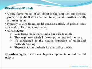
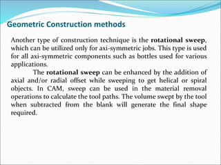
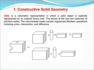
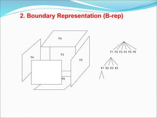
The document discusses different types of geometric models used in modeling including wireframe models, surface models, and solid models. It provides details on each type of model, including their advantages and disadvantages. Wireframe models are the simplest but use the least amount of memory and are easy to create. Surface models are more complex but provide more geometric constraints for engineering applications. Solid models provide the most complete representation and allow calculation of mass properties. The document also discusses different modeling approaches like constructive solid geometry (CSG) and boundary representation (B-rep) used for solid modeling.
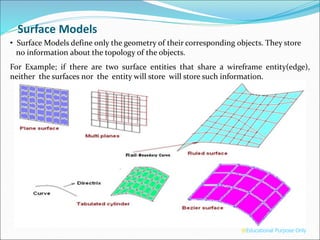


![Solids[1]](https://cdn.slidesharecdn.com/ss_thumbnails/solids1-150926053431-lva1-app6891-thumbnail.jpg?width=640&height=640&fit=bounds)