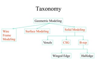
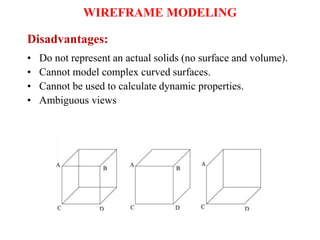
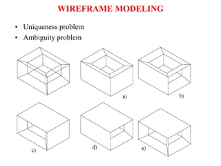
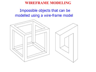
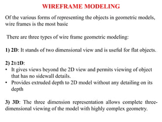
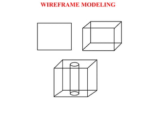
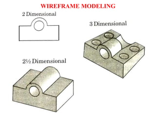
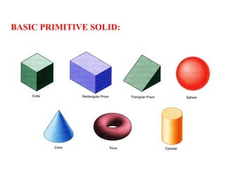
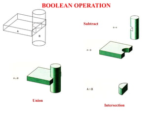
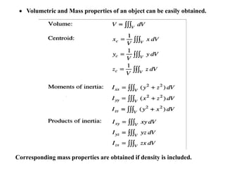
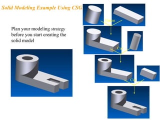
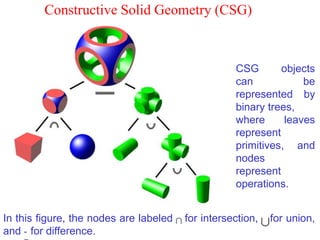
Introduction
to
Geometric Modeling
CAD/CAM/CAE
• To understand requirements for the information that is
generated during the geometric modelling stage.
• Study various types of geometric models possible
• Develop various methodologies used for geometric construction
such as sweep, surface models, solid models, etc.
• Recognize the various types of surfaces and their application as
used in geometric modelling
• Appreciate the concept of parametric modeling which is the
current mainstay of most of the 3D modeling systems
• Develop the various mathematical representations of the curves
used in the geometric construction
• Discuss the various CAD system requirements that need to be
considered while selecting a system for a given application
• Understand the concept of rapid prototyping and the various
methods available for the purpose.
OBJECTIVES OF GEOMETRIC MODELLING
• Stored in mathematical form, so modification can be easily done
• by commands like move, rotate, scale
BENEFITS OF GEOMETRIC MODELLING
GEOMETRIC MODELLING
• A prototype is needed for testing and optimizing design.
• Costly
• Time consuming
• CAD eliminates the need of developing prototype.
• Assists to evaluate the design.
• “Computer compatible mathematical description” of the
geometry of the object is called as geometric modelling.
• CAD software allows the mathematical description of the
object to be displayed as the image on the screen of computer
Steps through which designer create GM by using CAD software:
1) Creation of basic geometric objects:
• By using commands like points, lines, and circles
2) Transformations of the elements:
• By using transformation commands of the geometric elements
like scaling, translation etc.
3) Creation of the geometric model:
• Commands that cause integration of the objects or elements of
the geometric model to form the desired shape
• Merge, shell, loft, sweep
STEPS FOR CREATING GEOMETRIC MODEL
• During the process of geometric modeling
the computer
• converts various commands from the software into
mathematical models,
• stores them as the files and
• finally displays them as the image.
• The geometric models created by the designer can be opened at
any time for reviewing, editing or analysis.
STEPS FOR CREATING GEOMETRIC MODEL
• Wire Frame modeling
• Solid modeling
• Surface modeling
METHODS OF CREATING GEOMETRIC MODEL
Geometric Modeling
Surface Modeling
Solid Modeling
CSG
Voxels B-rep
Winged Edge Halfedge
Taxonomy
Wire
Frame
Modeling
WHY TO DRAW 3D MODELS?
• 3D models are easier to interpret.
• Simulation under real-life conditions.
• Less expensive than building a physical model.
• 3D models can be used to perform FEA (stress, deflection,
thermal…..).
• 3D models can be used directly in manufacturing, Computer
Numerical Control (CNC).
• Can be used for presentations and marketing.
3D MODELING
• Wireframe modeling
– modeling the curves of the part.
• Surface modeling
– Model the surfaces of the part, but without knowledge of
material.
• Solid modeling
– full solid representation
There are three basic types of three-dimensional computer geometric
modeling methods:
WIREFRAME MODELING
• W F models are drawn by using lines and curves.
• Connected by using their point coordinates or vertices.
• Simplest way of 3D representation.
• Difficult to understand and visualize the 3D model.
• Still used to generate simple geometric shapes and models.
WIREFRAME MODELING
• Entities used to generate model are classified as:
• Analytical curves: line, circle, hyperbola, parabola, E
• Synthetic curves: Hermite, Bezier, B-spline, Rational
• Basic curves are combined with desired continuity like C0, C1, C2
to get the required smoothness of the curve.
• Entities required are Line, Ellipse, Circle, Spline, Polygon etc
• Contains information about
the locations of all the points
(vertices) and edges in space
coordinates.
• Each vertex is defined by
x, y, z coordinate.
• Edges are defined by a pair of
vertices.
• Faces are defined as three or
more edges.
• Wireframe is a collection of
edges,
• there is no skin defining the
area between the edges.
WIREFRAME MODELING
Geometric model represented in wireframe model
WIREFRAME MODELING
• A cube can be generated with twelve edges generated from eight
vertices.
WIREFRAME MODELING
• Can quickly and efficiently convey information than multi-view
drawings.
• The only lines seen are the intersections of surfaces.
• Can be used as input for CNC machines to generate simple parts.
• Contain most of the information needed to create surface, solid and
higher order models.
Advantages:
WIREFRAME MODELING
• Do not represent an actual solids (no surface and volume).
• Cannot model complex curved surfaces.
• Cannot be used to calculate dynamic properties.
• Ambiguous views
Disadvantages:
WIREFRAME MODELING
• Uniqueness problem
• Ambiguity problem
WIREFRAME MODELING
WIREFRAME MODELING
Of the various forms of representing the objects in geometric models,
wire frames is the most basic
There are three types of wire frame geometric modeling:
1) 2D: It stands of two dimensional view and is useful for flat objects.
2) 21/2D:
• It gives views beyond the 2D view and permits viewing of object
that has no sidewall details.
• Provides extruded depth to 2D model without any detailing on its
depth
3) 3D: The three dimension representation allows complete three-
dimensional viewing of the model with highly complex geometry.
WIREFRAME MODELING
WIREFRAME MODELING
WIREFRAME MODELING
SURFACE MODELING
• Surface models define the surface features, as well as the edges, of
objects.
• A mathematical function describes the path of a curve (parametric
techniques).
• Surfaces are edited as single entities.
A surface model represents the skin of an object, these skins have no
thickness or material type.
SURFACE MODELING
SURFACE MODELING
• External shape of object can be obtained with no information
about internal shape.
• E.g. sheet metal cover, car body exteriors.
• The basic sketching tools required for surface generation are :
• extruded surface
• revolved surface
• swept surface
• offset surface
• A cube can be generated as surface model with six faces instead
of 12 edges
SURFACE MODELING
• Eliminates ambiguity and non-uniqueness present in WFM
• Renders the model for better visualization and presentation
• Objects appear more realistic.
• Provides the surface geometry for CNC machining.
• Provides the geometry needed for mold and die design.
• Can be used to design and analyze complex free-formed surfaces
(ship hulls, airplane wings, car bodies, …).
• Surface properties such as roughness, color and reflectivity can be
assigned and demonstrated.
ADVANTAGES:
SURFACE MODELING
• Surface models provide no information about the inside of
an object.
• Complicated computation, depending on the number of
surfaces .
DISADVANTAGES:
SURFACE MODELING
SOLID MODELS
• In the solid modeling, the solid definitions include vertices
(nodes), edges, surfaces, weight, and volume.
• The model is a complete and unambiguous representation of a
precisely enclosed and filled volume.
• It may be assessed for mass property calculations, analysis,
manufacturing, inspection, QC etc.
• Modeling software like SW, I, PE, I etc. are available.
• Most of the software provides various options to generate all three
types of models. (WF, S & S)
• Analysis automation and integration is possible only with solid
models has properties such as weight, moment of inertia, mass.
• Solid model consist of geometric and topological data
• Geometry  shape, size, location of geometric elements
• Topology connectivity and associativity of
geometric elements
SOLID MODELS
• Has all the advantages of surface models (uniqueness, non-
ambiguous, realistic, surface profile) plus volumetric information.
• Allows the designer to create multiple options for a design.
• 2D standard drawings, assembly drawing and exploded views are
generated form the 3D model.
ADVANTAGES:
SOLID MODELS
• Can easily be exported to different Finite Element Methods
programs for analysis.
• Can be used in newly manufacturing techniques;
– CIM, CAM and DFM & DFA
• Mass and volumetric properties of an object can be easily
obtained; total mass, mass center, area and mass moment of
inertia, volume, radius of gyration, …
ADVANTAGES:
SOLID MODELS
• More intensive computation than wireframe and surface
modeling.
• Requires more powerful computers (faster with more
memory and good graphics), not a problem any more.
DISADVANTAGES:
SOLID MODELS
WHY SOLID MODELING?
• Recall weakness of wireframe and surface modeling
– Ambiguous geometric description
– incomplete geometric description
– lack topological information
– Tedious modeling process
– Awkward user interface
Methods of Creating Solid Models
• Boundary Representation (B-rep), mostly used in finite
element programs.
• Constructive Solid Geometry (CSG), CAD packages;
Unigraphics, AutoCAD – 3D modeler.
• Parametric Modeling, CAD packages; Unigraphics,
SolidWorks, Inventor by AutoDesk, Pro/Engineer, ….
BASIC PRIMITIVE SOLID:
SET THEORY
Union Difference Intersection
• Union
– The sum of all points in each of two defined sets.
(logical “OR”)
– Also referred to as Add, Combine, Join, Merge
BOOLEAN OPERATION
• Difference
– The points in a source set minus the points common to a
second set. (logical “NOT”)
– Set must share common volume
– Also referred to as subtraction, remove, cut
BOOLEAN OPERATION
• Intersection
– Those points common to each of two defined sets (logical
“AND”)
– Set must share common volume
– Also referred to as common
BOOLEAN OPERATION
Union
Subtract
Intersection
BOOLEAN OPERATION
 Volumetric and Mass properties of an object can be easily obtained.
Corresponding mass properties are obtained if density is included.
Geometry
• Geometry is the actual dimensions that defines the entity of an
object
• It is called as metric information
• It includes
• length of line
• Angle between lines
• Centre of circle
• Radius of circle
• Geometry concerns size and shape of an object
• Topology generalizes many distance related concepts, such as
continuity, compactness and convergence.
• In topology we can consider two wholly different shapes in
geometry as the same because we can pull or push the lines or
move the vertices.
• It is the way in which entities are associated and connected.
Primitive Solids
Constructive Solid Geometry (CSG)
• The simplest the representation
are called primitives.
• Typically they are the objects of simple shape:
• cuboids, cylinders, prisms, pyramids, spheres, cones
• The set of allowable primitives is limited by each
software package.
• Some software packages allow CSG on curved objects
while other packages do not.
Constructive Solid Geometry (CSG)
• Constructive solid geometry (CSG) is a technique used in solid
modeling
• Constructive solid geometry allows a modeller to create a complex
surface or object by using Boolean operators to combine objects.
• Often CSG presents a model or surface that appears visually
complex,
• but is actually little more than cleverly combined or decombined
objects.
• CSG defines a model in terms of combining basic and generated
(using extrusion and sweeping operation) solid shapes.
Constructive Solid Geometry (CSG)
Union
Plan your modeling strategy
before you start creating the
solid model
Solid Modeling Example Using CSG
Cut
Cut
Constructive Solid Geometry (CSG)
CSG objects
can be
represented by
binary trees,
where leaves
represent
primitives, and
nodes
represent
operations.
In this figure, the nodes are labeled for intersection, for union,
and - for difference.
• CSG is powerful with high level command.
• Easy to construct a solid model – minimum
step.
• CSG modeling techniques lead to a concise
database less storage.
– Complete history of model is retained and can
be altered at any point.
• Can be converted to the corresponding
boundary representation.
Constructive solid geometry
(CSG) - advantage
• Only boolean operations are allowed in the modeling
process  with boolean operation alone, the range of
shapes to be modeled is severely restricted  not possible
to construct unusual shape.
• Requires a great deal of computation to derive the
information on the boundary, faces and edges which is
important for the interactive display/ manipulation of solid.
Constructive solid geometry
(CSG) - disadvantage
Solid Modeling
Boundary Representation (B-rep)
• A solid model is formed by defining the surfaces that form
its boundary (edges and surfaces)
• The face of a B-rep represents an oriented surface, there
are two sides to the surface; solid side (inside) and void
side (outside), unlike faces in a wireframe.
• B-rep model is created using Euler operation
• Many Finite Element Method (FEM) programs use this
method. Allows the interior meshing of the volume to be
more easily controlled.
• B-rep is a method to create solid models of physical objects
• B-rep solid is represented as a volume contained in a set of faces.
• It also contains topological information that defines the
relationship between faces.
• In B-rep a solid is bounded by its surface and has its exterior and
interior clearly defined.
• As it includes such topological information, a solid is represented
as a closed space in 3D space.
• The geometry can be described by its boundaries like vertices,
edges and surfaces.
• Each face is bounded by edge and each edge is bounded by
• Vertex: A unique point
(ordered triplet) in space.
• Edge :A finite, non-self
intersecting space curve
bounded by two vertices
that are not necessarily
distinct.
• Face :Finite, connected,
non-self intersecting
region of a closed,
orientable surface
bounded by one or more
loops.
A B-rep model of an object consists of faces, edges, vertices,
loops, genes (handle) and body.
• Loop :An ordered
alternating sequence of
vertices and edges. A
loop defines non-self
intersecting piecewise
closed space curve
which may be a
boundary of a face.
• Loop is a hole in a face
• Body :An independent
solid. Sometimes called a
shell has a set of faces that
bound single connected
closed volume. A
minimum body is a point
(vortex) which
topologically has one face
one vortex and no edges.
• A point is therefore called
a seminal or singular body.
• Genus : it is topological name for the number of handles or
through holes in an object
The total information present in a B-rep model is classified
into topological and geometrical data.,
The topological part of the data provides the relationship
among its objects such as vertices, edges and faces similar
to that used in WFM
Geometric information is usually equations of edges and
faces.
TYPES OF MODEL IN THIS SCHEME
There are two types of solid models in this scheme
a) Polyhedral solid or object
• Consists of planer faces connected at straight edges which in
turn are connected at vertices.
b) Curved solid or object:
• Similar to polyhedral objects but with curved faces and
edges.
Polyhedral objects are classified in to four class:
a) First class:
• do not have holes
• each face is bounded by a single set of connected edges
b) Second class
• face may have loop
c) Third class
• objects with holes that are not through
d) Fourth class
• Through holes
• Topologically holes are called as handle
• Topological name for no. of handles in object is genus
Euler Equation
Euler proved that polyhedra are topologically valid if they
satisfy the following equation
F – E + V – L = 2 ( B – G )
The simpler version of the above equation is
F – E + V = 2
Curved and Faceted B-rep model
• A closed cylindrical face has one edge and two vertices.
• A spherical face has one vertex and no edges.
• A boundary model of a closed cylinder has three faces (top,
bottom and cylindrical face) two vertices and one edge
connecting two vertices.
• The other edges are for visualization called as limb.
• The boundary model of a sphere consists of one face one
vertex and no edges
CONSTRAINT BASED MODELLING
FEATURE BASED MODELLING
•A feature is defined as a shape and operation to build parts.
•Shape is a 2D sketch
•Operation is activity that converts a sketch into 3D shape
FEATURE BASED MODELLING
STEPS TO CREATE OBJECT BY FEATURE
1. Create sketches
2. Create features
3. Use features to build parts
EXTRUDE
FEATURE BASED MODELLING
REVOLVE
FEATURE BASED MODELLING
SWEEP
FEATURE BASED MODELLING
LOFT
FEATURE BASED MODELLING
PATTERN
FEATURE BASED MODELLING
SPIRAL
FEATURE BASED MODELLING
•Shaft
•Pipe
•Boss
•Cut
•Hole
•Slot
•Pocket
•Shell
•Fillet
•Chamfer
•Rib
•Spring
FEATURE BASED MODELLING

introduction_to_solid_modeling__1_.pptx

  • 1.
  • 2.
    • To understandrequirements for the information that is generated during the geometric modelling stage. • Study various types of geometric models possible • Develop various methodologies used for geometric construction such as sweep, surface models, solid models, etc. • Recognize the various types of surfaces and their application as used in geometric modelling • Appreciate the concept of parametric modeling which is the current mainstay of most of the 3D modeling systems • Develop the various mathematical representations of the curves used in the geometric construction • Discuss the various CAD system requirements that need to be considered while selecting a system for a given application • Understand the concept of rapid prototyping and the various methods available for the purpose. OBJECTIVES OF GEOMETRIC MODELLING
  • 3.
    • Stored inmathematical form, so modification can be easily done • by commands like move, rotate, scale BENEFITS OF GEOMETRIC MODELLING
  • 4.
    GEOMETRIC MODELLING • Aprototype is needed for testing and optimizing design. • Costly • Time consuming • CAD eliminates the need of developing prototype. • Assists to evaluate the design. • “Computer compatible mathematical description” of the geometry of the object is called as geometric modelling. • CAD software allows the mathematical description of the object to be displayed as the image on the screen of computer
  • 5.
    Steps through whichdesigner create GM by using CAD software: 1) Creation of basic geometric objects: • By using commands like points, lines, and circles 2) Transformations of the elements: • By using transformation commands of the geometric elements like scaling, translation etc. 3) Creation of the geometric model: • Commands that cause integration of the objects or elements of the geometric model to form the desired shape • Merge, shell, loft, sweep STEPS FOR CREATING GEOMETRIC MODEL
  • 6.
    • During theprocess of geometric modeling the computer • converts various commands from the software into mathematical models, • stores them as the files and • finally displays them as the image. • The geometric models created by the designer can be opened at any time for reviewing, editing or analysis. STEPS FOR CREATING GEOMETRIC MODEL
  • 7.
    • Wire Framemodeling • Solid modeling • Surface modeling METHODS OF CREATING GEOMETRIC MODEL
  • 8.
    Geometric Modeling Surface Modeling SolidModeling CSG Voxels B-rep Winged Edge Halfedge Taxonomy Wire Frame Modeling
  • 9.
    WHY TO DRAW3D MODELS? • 3D models are easier to interpret. • Simulation under real-life conditions. • Less expensive than building a physical model. • 3D models can be used to perform FEA (stress, deflection, thermal…..). • 3D models can be used directly in manufacturing, Computer Numerical Control (CNC). • Can be used for presentations and marketing.
  • 10.
    3D MODELING • Wireframemodeling – modeling the curves of the part. • Surface modeling – Model the surfaces of the part, but without knowledge of material. • Solid modeling – full solid representation There are three basic types of three-dimensional computer geometric modeling methods:
  • 11.
    WIREFRAME MODELING • WF models are drawn by using lines and curves. • Connected by using their point coordinates or vertices. • Simplest way of 3D representation. • Difficult to understand and visualize the 3D model. • Still used to generate simple geometric shapes and models.
  • 12.
    WIREFRAME MODELING • Entitiesused to generate model are classified as: • Analytical curves: line, circle, hyperbola, parabola, E • Synthetic curves: Hermite, Bezier, B-spline, Rational • Basic curves are combined with desired continuity like C0, C1, C2 to get the required smoothness of the curve. • Entities required are Line, Ellipse, Circle, Spline, Polygon etc
  • 13.
    • Contains informationabout the locations of all the points (vertices) and edges in space coordinates. • Each vertex is defined by x, y, z coordinate. • Edges are defined by a pair of vertices. • Faces are defined as three or more edges. • Wireframe is a collection of edges, • there is no skin defining the area between the edges. WIREFRAME MODELING
  • 14.
    Geometric model representedin wireframe model WIREFRAME MODELING
  • 15.
    • A cubecan be generated with twelve edges generated from eight vertices. WIREFRAME MODELING
  • 16.
    • Can quicklyand efficiently convey information than multi-view drawings. • The only lines seen are the intersections of surfaces. • Can be used as input for CNC machines to generate simple parts. • Contain most of the information needed to create surface, solid and higher order models. Advantages: WIREFRAME MODELING
  • 17.
    • Do notrepresent an actual solids (no surface and volume). • Cannot model complex curved surfaces. • Cannot be used to calculate dynamic properties. • Ambiguous views Disadvantages: WIREFRAME MODELING
  • 18.
    • Uniqueness problem •Ambiguity problem WIREFRAME MODELING
  • 19.
  • 20.
    Of the variousforms of representing the objects in geometric models, wire frames is the most basic There are three types of wire frame geometric modeling: 1) 2D: It stands of two dimensional view and is useful for flat objects. 2) 21/2D: • It gives views beyond the 2D view and permits viewing of object that has no sidewall details. • Provides extruded depth to 2D model without any detailing on its depth 3) 3D: The three dimension representation allows complete three- dimensional viewing of the model with highly complex geometry. WIREFRAME MODELING
  • 21.
  • 22.
  • 23.
    SURFACE MODELING • Surfacemodels define the surface features, as well as the edges, of objects. • A mathematical function describes the path of a curve (parametric techniques). • Surfaces are edited as single entities. A surface model represents the skin of an object, these skins have no thickness or material type.
  • 24.
  • 25.
    SURFACE MODELING • Externalshape of object can be obtained with no information about internal shape. • E.g. sheet metal cover, car body exteriors. • The basic sketching tools required for surface generation are : • extruded surface • revolved surface • swept surface • offset surface
  • 26.
    • A cubecan be generated as surface model with six faces instead of 12 edges SURFACE MODELING
  • 27.
    • Eliminates ambiguityand non-uniqueness present in WFM • Renders the model for better visualization and presentation • Objects appear more realistic. • Provides the surface geometry for CNC machining. • Provides the geometry needed for mold and die design. • Can be used to design and analyze complex free-formed surfaces (ship hulls, airplane wings, car bodies, …). • Surface properties such as roughness, color and reflectivity can be assigned and demonstrated. ADVANTAGES: SURFACE MODELING
  • 28.
    • Surface modelsprovide no information about the inside of an object. • Complicated computation, depending on the number of surfaces . DISADVANTAGES: SURFACE MODELING
  • 29.
    SOLID MODELS • Inthe solid modeling, the solid definitions include vertices (nodes), edges, surfaces, weight, and volume. • The model is a complete and unambiguous representation of a precisely enclosed and filled volume. • It may be assessed for mass property calculations, analysis, manufacturing, inspection, QC etc. • Modeling software like SW, I, PE, I etc. are available. • Most of the software provides various options to generate all three types of models. (WF, S & S)
  • 30.
    • Analysis automationand integration is possible only with solid models has properties such as weight, moment of inertia, mass. • Solid model consist of geometric and topological data • Geometry  shape, size, location of geometric elements • Topology connectivity and associativity of geometric elements SOLID MODELS
  • 31.
    • Has allthe advantages of surface models (uniqueness, non- ambiguous, realistic, surface profile) plus volumetric information. • Allows the designer to create multiple options for a design. • 2D standard drawings, assembly drawing and exploded views are generated form the 3D model. ADVANTAGES: SOLID MODELS
  • 32.
    • Can easilybe exported to different Finite Element Methods programs for analysis. • Can be used in newly manufacturing techniques; – CIM, CAM and DFM & DFA • Mass and volumetric properties of an object can be easily obtained; total mass, mass center, area and mass moment of inertia, volume, radius of gyration, … ADVANTAGES: SOLID MODELS
  • 33.
    • More intensivecomputation than wireframe and surface modeling. • Requires more powerful computers (faster with more memory and good graphics), not a problem any more. DISADVANTAGES: SOLID MODELS
  • 34.
    WHY SOLID MODELING? •Recall weakness of wireframe and surface modeling – Ambiguous geometric description – incomplete geometric description – lack topological information – Tedious modeling process – Awkward user interface
  • 35.
    Methods of CreatingSolid Models • Boundary Representation (B-rep), mostly used in finite element programs. • Constructive Solid Geometry (CSG), CAD packages; Unigraphics, AutoCAD – 3D modeler. • Parametric Modeling, CAD packages; Unigraphics, SolidWorks, Inventor by AutoDesk, Pro/Engineer, ….
  • 36.
  • 37.
  • 38.
    • Union – Thesum of all points in each of two defined sets. (logical “OR”) – Also referred to as Add, Combine, Join, Merge BOOLEAN OPERATION
  • 39.
    • Difference – Thepoints in a source set minus the points common to a second set. (logical “NOT”) – Set must share common volume – Also referred to as subtraction, remove, cut BOOLEAN OPERATION
  • 40.
    • Intersection – Thosepoints common to each of two defined sets (logical “AND”) – Set must share common volume – Also referred to as common BOOLEAN OPERATION
  • 41.
  • 42.
     Volumetric andMass properties of an object can be easily obtained. Corresponding mass properties are obtained if density is included.
  • 43.
    Geometry • Geometry isthe actual dimensions that defines the entity of an object • It is called as metric information • It includes • length of line • Angle between lines • Centre of circle • Radius of circle • Geometry concerns size and shape of an object
  • 44.
    • Topology generalizesmany distance related concepts, such as continuity, compactness and convergence. • In topology we can consider two wholly different shapes in geometry as the same because we can pull or push the lines or move the vertices. • It is the way in which entities are associated and connected.
  • 47.
  • 48.
    • The simplestthe representation are called primitives. • Typically they are the objects of simple shape: • cuboids, cylinders, prisms, pyramids, spheres, cones • The set of allowable primitives is limited by each software package. • Some software packages allow CSG on curved objects while other packages do not. Constructive Solid Geometry (CSG)
  • 49.
    • Constructive solidgeometry (CSG) is a technique used in solid modeling • Constructive solid geometry allows a modeller to create a complex surface or object by using Boolean operators to combine objects. • Often CSG presents a model or surface that appears visually complex, • but is actually little more than cleverly combined or decombined objects. • CSG defines a model in terms of combining basic and generated (using extrusion and sweeping operation) solid shapes. Constructive Solid Geometry (CSG)
  • 50.
    Union Plan your modelingstrategy before you start creating the solid model Solid Modeling Example Using CSG Cut Cut
  • 51.
    Constructive Solid Geometry(CSG) CSG objects can be represented by binary trees, where leaves represent primitives, and nodes represent operations. In this figure, the nodes are labeled for intersection, for union, and - for difference.
  • 52.
    • CSG ispowerful with high level command. • Easy to construct a solid model – minimum step. • CSG modeling techniques lead to a concise database less storage. – Complete history of model is retained and can be altered at any point. • Can be converted to the corresponding boundary representation. Constructive solid geometry (CSG) - advantage
  • 53.
    • Only booleanoperations are allowed in the modeling process  with boolean operation alone, the range of shapes to be modeled is severely restricted  not possible to construct unusual shape. • Requires a great deal of computation to derive the information on the boundary, faces and edges which is important for the interactive display/ manipulation of solid. Constructive solid geometry (CSG) - disadvantage
  • 54.
    Solid Modeling Boundary Representation(B-rep) • A solid model is formed by defining the surfaces that form its boundary (edges and surfaces) • The face of a B-rep represents an oriented surface, there are two sides to the surface; solid side (inside) and void side (outside), unlike faces in a wireframe. • B-rep model is created using Euler operation • Many Finite Element Method (FEM) programs use this method. Allows the interior meshing of the volume to be more easily controlled.
  • 55.
    • B-rep isa method to create solid models of physical objects • B-rep solid is represented as a volume contained in a set of faces. • It also contains topological information that defines the relationship between faces. • In B-rep a solid is bounded by its surface and has its exterior and interior clearly defined. • As it includes such topological information, a solid is represented as a closed space in 3D space. • The geometry can be described by its boundaries like vertices, edges and surfaces. • Each face is bounded by edge and each edge is bounded by
  • 56.
    • Vertex: Aunique point (ordered triplet) in space. • Edge :A finite, non-self intersecting space curve bounded by two vertices that are not necessarily distinct. • Face :Finite, connected, non-self intersecting region of a closed, orientable surface bounded by one or more loops. A B-rep model of an object consists of faces, edges, vertices, loops, genes (handle) and body.
  • 57.
    • Loop :Anordered alternating sequence of vertices and edges. A loop defines non-self intersecting piecewise closed space curve which may be a boundary of a face. • Loop is a hole in a face
  • 58.
    • Body :Anindependent solid. Sometimes called a shell has a set of faces that bound single connected closed volume. A minimum body is a point (vortex) which topologically has one face one vortex and no edges. • A point is therefore called a seminal or singular body. • Genus : it is topological name for the number of handles or through holes in an object
  • 59.
    The total informationpresent in a B-rep model is classified into topological and geometrical data., The topological part of the data provides the relationship among its objects such as vertices, edges and faces similar to that used in WFM Geometric information is usually equations of edges and faces.
  • 60.
    TYPES OF MODELIN THIS SCHEME There are two types of solid models in this scheme a) Polyhedral solid or object • Consists of planer faces connected at straight edges which in turn are connected at vertices. b) Curved solid or object: • Similar to polyhedral objects but with curved faces and edges.
  • 61.
    Polyhedral objects areclassified in to four class: a) First class: • do not have holes • each face is bounded by a single set of connected edges b) Second class • face may have loop c) Third class • objects with holes that are not through d) Fourth class • Through holes • Topologically holes are called as handle • Topological name for no. of handles in object is genus
  • 63.
    Euler Equation Euler provedthat polyhedra are topologically valid if they satisfy the following equation F – E + V – L = 2 ( B – G ) The simpler version of the above equation is F – E + V = 2
  • 65.
    Curved and FacetedB-rep model • A closed cylindrical face has one edge and two vertices. • A spherical face has one vertex and no edges. • A boundary model of a closed cylinder has three faces (top, bottom and cylindrical face) two vertices and one edge connecting two vertices. • The other edges are for visualization called as limb. • The boundary model of a sphere consists of one face one vertex and no edges
  • 66.
  • 67.
  • 68.
  • 69.
  • 70.
  • 71.
  • 72.
    FEATURE BASED MODELLING •Afeature is defined as a shape and operation to build parts. •Shape is a 2D sketch •Operation is activity that converts a sketch into 3D shape
  • 73.
    FEATURE BASED MODELLING STEPSTO CREATE OBJECT BY FEATURE 1. Create sketches 2. Create features 3. Use features to build parts
  • 74.
  • 75.
  • 76.
  • 77.
  • 78.
  • 79.
  • 80.

Editor's Notes

  • #3 Understand the various requirements for the information that is generated during the geometric modelling stage. Study various types of geometric models possible and their applications Develop various methodologies used for geometric construction such as sweep, surface models, solid models, etc. Recognize the various types of surfaces and their application as used in geometric modelling Appreciate the concept of parametric modeling which is the current mainstay of most of the 3D modeling systems Develop the various mathematical representations of the curves used in the geometric construction Discuss the various CAD system requirements that need to be considered while selecting a system for a given application Understand the concept of rapid prototyping and the various methods available for the purpose.
  • #4 Understand the various requirements for the information that is generated during the geometric modelling stage. Study various types of geometric models possible and their applications Develop various methodologies used for geometric construction such as sweep, surface models, solid models, etc. Recognize the various types of surfaces and their application as used in geometric modelling Appreciate the concept of parametric modeling which is the current mainstay of most of the 3D modeling systems Develop the various mathematical representations of the curves used in the geometric construction Discuss the various CAD system requirements that need to be considered while selecting a system for a given application Understand the concept of rapid prototyping and the various methods available for the purpose.
  • #6 There are three steps in which the designer can create geometric models by using CAD software: Creation of basic geometric objects: Designer creates basic geometric elements by using commands like points, lines, and circles 2) Transformations of the elements: Designer uses commands like scaling, rotation and other related transformations of the geometric elements 3) Creation of the geometric model: Designer uses such commands that cause integration of the objects or elements of the geometric model to form the desired shape.