Downloaded 346 times


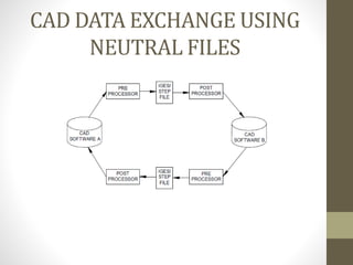
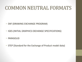


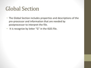


The document discusses the Initial Graphics Exchange Specification (IGES) format, which is a neutral file format used for CAD data exchange between different software packages. It describes the key components of an IGES file, including the start section, global section, directory entry section, parameter data section, and terminal section. The global section provides metadata about the file. The directory entry and parameter data sections define the geometric entities using parameters. Common entities that can be represented include lines, circles, surfaces of revolution. IGES aims to enable translation between different CAD systems by providing a common format for exchange of geometry and topology data.