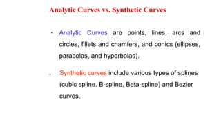
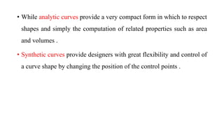
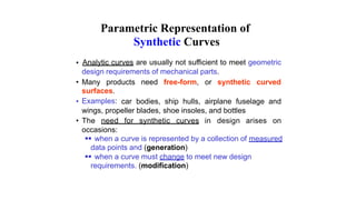
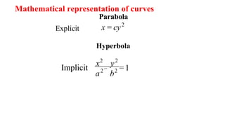
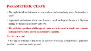
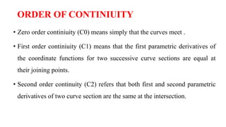
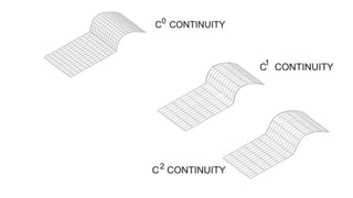
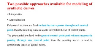
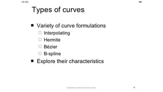
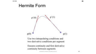
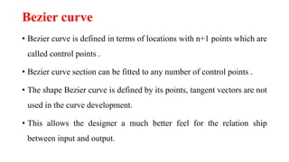
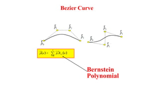
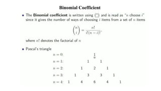
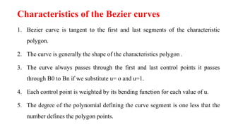
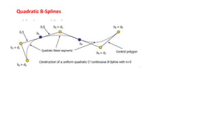
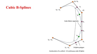
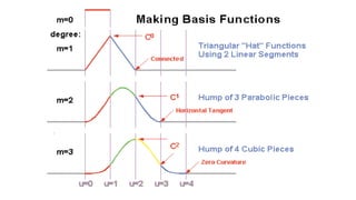
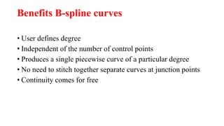
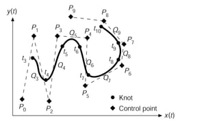
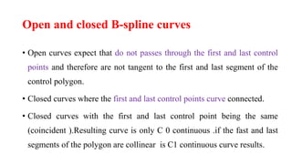
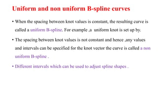
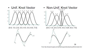
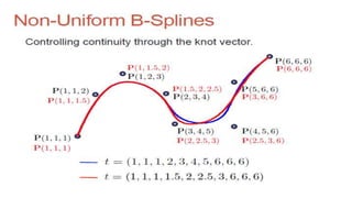
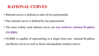
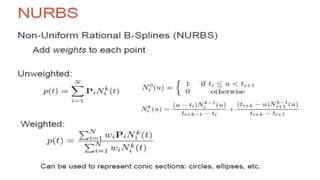
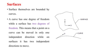
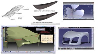
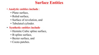
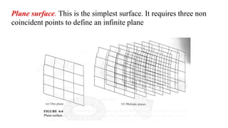
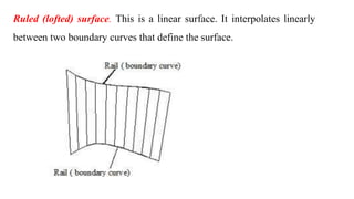
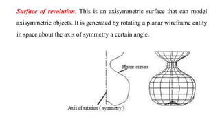
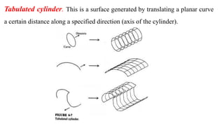
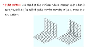
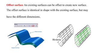
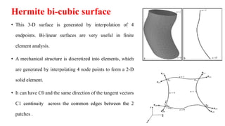
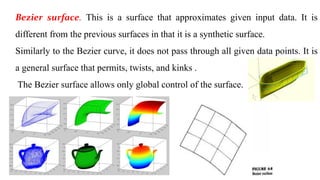
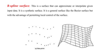
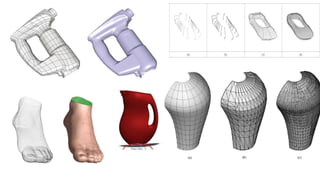
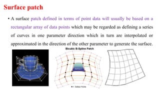
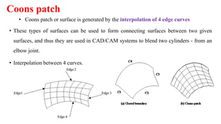
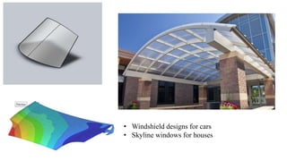
S.DHARANI KUMAR
Asst.professor
Department of Mechanical
Engineering
SRI ESHWAR COLLEGE OF
ENGINEERING ,COIMBATORE
,INDIA
UNIT-2
Curves & Surfaces
Analytic Curves vs. Synthetic Curves
• Analytic Curves are points, lines, arcs and
circles, fillets and chamfers, and conics (ellipses,
parabolas, and hyperbolas).
• Synthetic curves include various types of splines
(cubic spline, B-spline, Beta-spline) and Bezier
curves.
• While analytic curves provide a very compact form in which to respect
shapes and simply the computation of related properties such as area
and volumes .
• Synthetic curves provide designers with great flexibility and control of
a curve shape by changing the position of the control points .
Parametric Representation of
Synthetic Curves
Analytic curves are usually not sufficient to meet geometric•
design requirements of mechanical parts.
• Many products need free-form, or synthetic curved
surfaces.
Examples:• car bodies, ship hulls, airplane fuselage and
wings, propeller blades, shoe insoles, and bottles
• The need for synthetic curves in design arises on
occasions:
 when a curve is represented by a collection of measured
data points and (generation)
 when a curve must change to meet new design
requirements. (modification)
Parabola
x = cy2
Explicit
Hyperbola
x2
y2
=1−Implicit
a2
b2
Mathematical representation of curves
PARAMETERIC CURVE
• The explicit and implicit curve representations can be used only when the function is
know.
• In practical applications, where complex curves such as shape of the car or a flight are
needed the function is normally unknown.
• The defining equations of this type of curve are in terms of a simple and common
independent variable known as parametric variable.
X= x (u ) ,Y = y (u)
x & y are co-ordinates of the points on the curve which are the functions of parameter
variable is constrained in the interval .
The Order of Continuity
The order of continuity is a term usually used to measure
(C0 , C1 C2).,the degree of continuous derivatives
x x
Simplest Case
Linear
Segment High order polynomial may lead to
“ripples”
n
yi = ai0 + ai1x + ... + ain
x
yi = ai0 + ai1x
y
i=2
i=1 i=3
y
i=2
i=1 i=3
ORDER OF CONTINIUITY
• Zero order continiuity (C0) means simply that the curves meet .
• First order continiuity (C1) means that the first parametric derivatives of
the coordinate functions for two successive curve sections are equal at
their joining points.
• Second order continuity (C2) refers that both first and second parametric
derivatives of two curve section are the same at the intersection.
Two possible approaches available for modeling of
synthetic curves
• Interpolation
• Approximation
Polynomial sections are fitted so that the curve passes through each control
point, then the resulting curve is said to interpolate the set of control points .
The polynomial are fitted to the general control point path without necessarily
passing through any control point then the resulting curve is said to
approximate the set of control points.
DHARANI KUMAR.S/AP/MECH/SECE
Hermite curve
• Hermite curve is a type of cubic spline described by French mathematician Charles
hermite.
• Splines are functions which are used to fit a curve through a number of data points.
• Hermite cubic spline is the interpolation curve .
• Cubic polynomial has 4 coefficients and 4 conditions to be evaluate.
• Hermite cubic splines using two data points at its ends and two tangent vectors at the
these points.
Disadvantage
• It not used very popular due to the need for tangent vectors or slopes
to define the curve.
• For example changing the position of data points or end slopes
changes the entire shape of the spline ,which does not provide the
initiative feel required for design.
Bezier curve
Bezier curve
• Bezier curve is defined in terms of locations with n+1 points which are
called control points .
• Bezier curve section can be fitted to any number of control points .
• The shape Bezier curve is defined by its points, tangent vectors are not
used in the curve development.
• This allows the designer a much better feel for the relation ship
between input and output.
p0
p1
p3
p2
p2
p3
p0
p1
Bezier Curve
rr r
r
p3
r
r
r
p1
p(u) = pi Bi ,n (u)∑
n
i=0
rp0
p0
p3
p2
p2p1
Bernstein
Polynomial
Binomial Coefficient
Characteristics of the Bezier curves
1. Bezier curve is tangent to the first and last segments of the characteristic
polygon.
2. The curve is generally the shape of the characteristics polygon .
3. The curve always passes through the first and last control points it passes
through B0 to Bn if we substitute u= o and u=1.
4. Each control point is weighted by its bending function for each value of u.
5. The degree of the polynomial defining the curve segment is one less that the
number defines the polygon points.
Characteristics of the Bezier curves
6. Reversing the sequence of control point does not change the shape of the curve.
7.The curve is invariant under on affine transformation.
8.A closed Bezier curve can simply be generated by closing its characteristic
polygon.
9.The curve lies entirely within the convex hull formed by four points.
10.The curve shape can be modified either by changing one or by more vertices
of its polygon .
B-SPLINE
• B-Spline curves provide another effective method Bezier of generating
curves defined by data points.
• They provide local control of the curve shape as opposed to global
control by using blending functions which provide local influence.
• Control points sometimes called deboor points.
• The selected set of subinterval endpoints u is referred as a Knot
vector.
Characteristics of the B spline curves
1. The local control of the curve an be obtained by changing the position of
a control point.
2. The B-Spline curves do not pass through the first and last control points
except when the linear blending functions are used.
3. B-Spline allow us to vary the number of control points used to a design
a curve without changing the degree of the polynomial .
4. The B-spline curve becomes a Bezier curve if K equals the number of
control points (n+1) .
5.Multiple control points results the regions of high curvature of B-spline curve.
6.The number of degree of curve increases ,the curve tightness if the degree of
curve is less the control points will be closer.
7.As the degree of curve increases, it is more difficult to control and calculate
accurately. Thus, a cubic B-spline curve is sufficient for many applications .
Characteristics of the B spline curves
Linear Interpolation
P1
P2
P3
P4
Quadratic B-Splines
Cubic B-Splines
d0
d1
d3d5
d2
d4
b0 =
b1 =
b9 =
= b8
B-Spline polygon
Construction of a uniform C2-continuous cubic B-Spline
b4
b5
b7
b2
b3
b6
Cubic Bézier segments
Benefits B-spline curves
• User defines degree
• Independent of the number of control points
• Produces a single piecewise curve of a particular degree
• No need to stitch together separate curves at junction points
• Continuity comes for free
Open and closed B-spline curves
• Open curves expect that do not passes through the first and last control
points and therefore are not tangent to the first and last segment of the
control polygon.
• Closed curves where the first and last control points curve connected.
• Closed curves with the first and last control point being the same
(coincident ).Resulting curve is only C 0 continuous .if the fast and last
segments of the polygon are collinear is C1 continuous curve results.
Uniform and non uniform B-spline curves
• When the spacing between knot values is constant, the resulting curve is
called a uniform B-spline. For example ,a uniform knot is set up by.
• The spacing between knot values is not constant and hence ,any values
and intervals can be specified for the knot vector the curve is called a non
uniform B-spline .
• Different intervals which can be used to adjust spline shapes .
RATIONAL CURVES
• Rational curves is defined as ratio of two polynomials.
• Non rational curves is defined by one polynomials.
• The most widely used rational curves are non uniform rational B-splines
(NURBS)
• NURBS is capable of representing in a single form non –rational B-splines
and Bezier curves as well as linear and quadratic analytic curves.
Characteristics of rational curves
1. Rational curve can handle both analytical and synthetic curves.
2. Rational curve represents a point with homogenous coordinate system where a
3D coordinate system is expressed as (wi x, wi y ,wi z,wi).
3. Some information of simple shapes may be lost due to conversion in to rational
curve.
4. Using same control points with different weights ,different curves can be
generated.
5. The weight associated with each control point can affect the curve locally and the
curve is pulled towards the control point with increases valued of its weight wi.
Benefits of Rational Spline Curves
• Invariant under rotation, scale, translation, perspective
transformations.
• Can precisely define the conic sections and other analytic functions.
Surfaces
• Surface themselves are bounded by
curves.
• A curve has one degree of freedom
while a surface has two degrees of
freedom. This means that a point on a
curve can be moved in only one
independent direction while on
surfaces it has two independent
directions to move.
Curves and surfaces are the basic building blocks in
the following designs:
i. Body panels of passenger cars
ii. Aircraft bulk heads and other fuselage structures, slats, flaps, wings etc.
iii. Marine structures
iv. Consumer products like plastic containers, telephones etc. The NC tool
path for complex shaped components that are encountered in aerospace
structures, dies and moulds and automobile body panels.
Advantages
• Surface modeling can be used to preform interference checking.
• Surface modeling can be used check the aesthetic look of the product.
• Surface model precisely define the part geometry such as surface and
boundaries, they can help to produce NC machines instructions
automatically.
• Complex surfaces features such as shoes ,car panels, doors etc. can be
created very easily.
Disadvantages
• Difficult to construct.
• Difficult to calculate mass property.
• More time is required for creation.
• Requires high storage space.
• Also requires more time for manipulation.
Surface Entities
• Analytic entities include :
• Plane surface,
• Ruled surface,
• Surface of revolution, and
• Tabulated cylinder.
• Synthetic entities include
• Hermite Cubic spline surface,
• B-spline surface,
• Bezier surface, and
• Coons patches.
Plane surface. This is the simplest surface. It requires three non
coincident points to define an infinite plane
Ruled (lofted) surface. This is a linear surface. It interpolates linearly
between two boundary curves that define the surface.
Surface of revolution. This is an axisymmetric surface that can model
axisymmetric objects. It is generated by rotating a planar wireframe entity
in space about the axis of symmetry a certain angle.
Tabulated cylinder. This is a surface generated by translating a planar curve
a certain distance along a specified direction (axis of the cylinder).
• Fillet surface is a blend of two surfaces which intersect each other. If
required, a fillet of specified radius may be provided at the intersection of
two surfaces.
Offset surface An existing surfaces can be offset to create new surface.
The offset surface is identical in shape with the existing surface, but may
have the different dimensions.
Hermite bi-cubic surface
• This 3-D surface is generated by interpolation of 4
endpoints. Bi-linear surfaces are very useful in finite
element analysis.
• A mechanical structure is discretized into elements, which
are generated by interpolating 4 node points to form a 2-D
solid element.
• It can have C0 and the same direction of the tangent vectors
C1 continuity across the common edges between the 2
patches .
Bezier surface. This is a surface that approximates given input data. It is
different from the previous surfaces in that it is a synthetic surface.
Similarly to the Bezier curve, it does not pass through all given data points. It is
a general surface that permits, twists, and kinks .
The Bezier surface allows only global control of the surface.
Bezier surface
• It can have C0 and C1 continuity
• Bezier surface is superior to a hermit surface in that it does not require
tangent vector or twist vector to define the surface .
• Main disadvantages changing one or more control points affects the
shape of the whole surface.
B-spline surface. This is a surface that can approximate or interpolate given
input data. It is a synthetic surface. It is a general surface like the Bezier surface but
with the advantage of permitting local control of the surface.
Surface patch
• A surface patch defined in terms of point data will usually be based on a
rectangular array of data points which may be regarded as defining a series
of curves in one parameter direction which in turn are interpolated or
approximated in the direction of the other parameter to generate the surface.
Coons patch
• These types of surfaces can be used to form connecting surfaces between two given
surfaces, and thus they are used in CAD/CAM systems to blend two cylinders - from an
elbow joint.
• Interpolation between 4 curves.
• Coons patch or surface is generated by the interpolation of 4 edge curves
• Coons patch is particularly useful in blending four prescribed intersecting
curves which form a closed boundary .
• The two ruled surfaces connecting the two pairs of boundary curves
might satisfy the boundary curve conditions and produces the coons
patch.
• Main drawback of the bilinear blended coons patch's it that it only
provides C0 continuity between adjacent patches even it their curves
form a C1 continuity network .
• Windshield designs for cars
• Skyline windows for houses

Unit 2 curves & surfaces

  • 1.
    S.DHARANI KUMAR Asst.professor Department ofMechanical Engineering SRI ESHWAR COLLEGE OF ENGINEERING ,COIMBATORE ,INDIA UNIT-2 Curves & Surfaces
  • 2.
    Analytic Curves vs.Synthetic Curves • Analytic Curves are points, lines, arcs and circles, fillets and chamfers, and conics (ellipses, parabolas, and hyperbolas). • Synthetic curves include various types of splines (cubic spline, B-spline, Beta-spline) and Bezier curves.
  • 3.
    • While analyticcurves provide a very compact form in which to respect shapes and simply the computation of related properties such as area and volumes . • Synthetic curves provide designers with great flexibility and control of a curve shape by changing the position of the control points .
  • 4.
    Parametric Representation of SyntheticCurves Analytic curves are usually not sufficient to meet geometric• design requirements of mechanical parts. • Many products need free-form, or synthetic curved surfaces. Examples:• car bodies, ship hulls, airplane fuselage and wings, propeller blades, shoe insoles, and bottles • The need for synthetic curves in design arises on occasions:  when a curve is represented by a collection of measured data points and (generation)  when a curve must change to meet new design requirements. (modification)
  • 5.
  • 6.
    PARAMETERIC CURVE • Theexplicit and implicit curve representations can be used only when the function is know. • In practical applications, where complex curves such as shape of the car or a flight are needed the function is normally unknown. • The defining equations of this type of curve are in terms of a simple and common independent variable known as parametric variable. X= x (u ) ,Y = y (u) x & y are co-ordinates of the points on the curve which are the functions of parameter variable is constrained in the interval .
  • 7.
    The Order ofContinuity The order of continuity is a term usually used to measure (C0 , C1 C2).,the degree of continuous derivatives x x Simplest Case Linear Segment High order polynomial may lead to “ripples” n yi = ai0 + ai1x + ... + ain x yi = ai0 + ai1x y i=2 i=1 i=3 y i=2 i=1 i=3
  • 8.
    ORDER OF CONTINIUITY •Zero order continiuity (C0) means simply that the curves meet . • First order continiuity (C1) means that the first parametric derivatives of the coordinate functions for two successive curve sections are equal at their joining points. • Second order continuity (C2) refers that both first and second parametric derivatives of two curve section are the same at the intersection.
  • 10.
    Two possible approachesavailable for modeling of synthetic curves • Interpolation • Approximation Polynomial sections are fitted so that the curve passes through each control point, then the resulting curve is said to interpolate the set of control points . The polynomial are fitted to the general control point path without necessarily passing through any control point then the resulting curve is said to approximate the set of control points.
  • 11.
  • 12.
  • 13.
    Hermite curve • Hermitecurve is a type of cubic spline described by French mathematician Charles hermite. • Splines are functions which are used to fit a curve through a number of data points. • Hermite cubic spline is the interpolation curve . • Cubic polynomial has 4 coefficients and 4 conditions to be evaluate. • Hermite cubic splines using two data points at its ends and two tangent vectors at the these points.
  • 14.
    Disadvantage • It notused very popular due to the need for tangent vectors or slopes to define the curve. • For example changing the position of data points or end slopes changes the entire shape of the spline ,which does not provide the initiative feel required for design.
  • 15.
  • 16.
    Bezier curve • Beziercurve is defined in terms of locations with n+1 points which are called control points . • Bezier curve section can be fitted to any number of control points . • The shape Bezier curve is defined by its points, tangent vectors are not used in the curve development. • This allows the designer a much better feel for the relation ship between input and output.
  • 17.
    p0 p1 p3 p2 p2 p3 p0 p1 Bezier Curve rr r r p3 r r r p1 p(u)= pi Bi ,n (u)∑ n i=0 rp0 p0 p3 p2 p2p1 Bernstein Polynomial
  • 18.
  • 19.
    Characteristics of theBezier curves 1. Bezier curve is tangent to the first and last segments of the characteristic polygon. 2. The curve is generally the shape of the characteristics polygon . 3. The curve always passes through the first and last control points it passes through B0 to Bn if we substitute u= o and u=1. 4. Each control point is weighted by its bending function for each value of u. 5. The degree of the polynomial defining the curve segment is one less that the number defines the polygon points.
  • 20.
    Characteristics of theBezier curves 6. Reversing the sequence of control point does not change the shape of the curve. 7.The curve is invariant under on affine transformation. 8.A closed Bezier curve can simply be generated by closing its characteristic polygon. 9.The curve lies entirely within the convex hull formed by four points. 10.The curve shape can be modified either by changing one or by more vertices of its polygon .
  • 21.
    B-SPLINE • B-Spline curvesprovide another effective method Bezier of generating curves defined by data points. • They provide local control of the curve shape as opposed to global control by using blending functions which provide local influence. • Control points sometimes called deboor points. • The selected set of subinterval endpoints u is referred as a Knot vector.
  • 22.
    Characteristics of theB spline curves 1. The local control of the curve an be obtained by changing the position of a control point. 2. The B-Spline curves do not pass through the first and last control points except when the linear blending functions are used. 3. B-Spline allow us to vary the number of control points used to a design a curve without changing the degree of the polynomial . 4. The B-spline curve becomes a Bezier curve if K equals the number of control points (n+1) .
  • 23.
    5.Multiple control pointsresults the regions of high curvature of B-spline curve. 6.The number of degree of curve increases ,the curve tightness if the degree of curve is less the control points will be closer. 7.As the degree of curve increases, it is more difficult to control and calculate accurately. Thus, a cubic B-spline curve is sufficient for many applications . Characteristics of the B spline curves
  • 24.
  • 25.
  • 26.
    Cubic B-Splines d0 d1 d3d5 d2 d4 b0 = b1= b9 = = b8 B-Spline polygon Construction of a uniform C2-continuous cubic B-Spline b4 b5 b7 b2 b3 b6 Cubic Bézier segments
  • 28.
    Benefits B-spline curves •User defines degree • Independent of the number of control points • Produces a single piecewise curve of a particular degree • No need to stitch together separate curves at junction points • Continuity comes for free
  • 30.
    Open and closedB-spline curves • Open curves expect that do not passes through the first and last control points and therefore are not tangent to the first and last segment of the control polygon. • Closed curves where the first and last control points curve connected. • Closed curves with the first and last control point being the same (coincident ).Resulting curve is only C 0 continuous .if the fast and last segments of the polygon are collinear is C1 continuous curve results.
  • 31.
    Uniform and nonuniform B-spline curves • When the spacing between knot values is constant, the resulting curve is called a uniform B-spline. For example ,a uniform knot is set up by. • The spacing between knot values is not constant and hence ,any values and intervals can be specified for the knot vector the curve is called a non uniform B-spline . • Different intervals which can be used to adjust spline shapes .
  • 34.
    RATIONAL CURVES • Rationalcurves is defined as ratio of two polynomials. • Non rational curves is defined by one polynomials. • The most widely used rational curves are non uniform rational B-splines (NURBS) • NURBS is capable of representing in a single form non –rational B-splines and Bezier curves as well as linear and quadratic analytic curves.
  • 37.
    Characteristics of rationalcurves 1. Rational curve can handle both analytical and synthetic curves. 2. Rational curve represents a point with homogenous coordinate system where a 3D coordinate system is expressed as (wi x, wi y ,wi z,wi). 3. Some information of simple shapes may be lost due to conversion in to rational curve. 4. Using same control points with different weights ,different curves can be generated. 5. The weight associated with each control point can affect the curve locally and the curve is pulled towards the control point with increases valued of its weight wi.
  • 39.
    Benefits of RationalSpline Curves • Invariant under rotation, scale, translation, perspective transformations. • Can precisely define the conic sections and other analytic functions.
  • 40.
    Surfaces • Surface themselvesare bounded by curves. • A curve has one degree of freedom while a surface has two degrees of freedom. This means that a point on a curve can be moved in only one independent direction while on surfaces it has two independent directions to move.
  • 42.
    Curves and surfacesare the basic building blocks in the following designs: i. Body panels of passenger cars ii. Aircraft bulk heads and other fuselage structures, slats, flaps, wings etc. iii. Marine structures iv. Consumer products like plastic containers, telephones etc. The NC tool path for complex shaped components that are encountered in aerospace structures, dies and moulds and automobile body panels.
  • 43.
    Advantages • Surface modelingcan be used to preform interference checking. • Surface modeling can be used check the aesthetic look of the product. • Surface model precisely define the part geometry such as surface and boundaries, they can help to produce NC machines instructions automatically. • Complex surfaces features such as shoes ,car panels, doors etc. can be created very easily.
  • 44.
    Disadvantages • Difficult toconstruct. • Difficult to calculate mass property. • More time is required for creation. • Requires high storage space. • Also requires more time for manipulation.
  • 45.
    Surface Entities • Analyticentities include : • Plane surface, • Ruled surface, • Surface of revolution, and • Tabulated cylinder. • Synthetic entities include • Hermite Cubic spline surface, • B-spline surface, • Bezier surface, and • Coons patches.
  • 46.
    Plane surface. Thisis the simplest surface. It requires three non coincident points to define an infinite plane
  • 47.
    Ruled (lofted) surface.This is a linear surface. It interpolates linearly between two boundary curves that define the surface.
  • 48.
    Surface of revolution.This is an axisymmetric surface that can model axisymmetric objects. It is generated by rotating a planar wireframe entity in space about the axis of symmetry a certain angle.
  • 49.
    Tabulated cylinder. Thisis a surface generated by translating a planar curve a certain distance along a specified direction (axis of the cylinder).
  • 50.
    • Fillet surfaceis a blend of two surfaces which intersect each other. If required, a fillet of specified radius may be provided at the intersection of two surfaces.
  • 51.
    Offset surface Anexisting surfaces can be offset to create new surface. The offset surface is identical in shape with the existing surface, but may have the different dimensions.
  • 52.
    Hermite bi-cubic surface •This 3-D surface is generated by interpolation of 4 endpoints. Bi-linear surfaces are very useful in finite element analysis. • A mechanical structure is discretized into elements, which are generated by interpolating 4 node points to form a 2-D solid element. • It can have C0 and the same direction of the tangent vectors C1 continuity across the common edges between the 2 patches .
  • 53.
    Bezier surface. Thisis a surface that approximates given input data. It is different from the previous surfaces in that it is a synthetic surface. Similarly to the Bezier curve, it does not pass through all given data points. It is a general surface that permits, twists, and kinks . The Bezier surface allows only global control of the surface.
  • 54.
    Bezier surface • Itcan have C0 and C1 continuity • Bezier surface is superior to a hermit surface in that it does not require tangent vector or twist vector to define the surface . • Main disadvantages changing one or more control points affects the shape of the whole surface.
  • 55.
    B-spline surface. Thisis a surface that can approximate or interpolate given input data. It is a synthetic surface. It is a general surface like the Bezier surface but with the advantage of permitting local control of the surface.
  • 57.
    Surface patch • Asurface patch defined in terms of point data will usually be based on a rectangular array of data points which may be regarded as defining a series of curves in one parameter direction which in turn are interpolated or approximated in the direction of the other parameter to generate the surface.
  • 58.
    Coons patch • Thesetypes of surfaces can be used to form connecting surfaces between two given surfaces, and thus they are used in CAD/CAM systems to blend two cylinders - from an elbow joint. • Interpolation between 4 curves. • Coons patch or surface is generated by the interpolation of 4 edge curves
  • 59.
    • Coons patchis particularly useful in blending four prescribed intersecting curves which form a closed boundary . • The two ruled surfaces connecting the two pairs of boundary curves might satisfy the boundary curve conditions and produces the coons patch. • Main drawback of the bilinear blended coons patch's it that it only provides C0 continuity between adjacent patches even it their curves form a C1 continuity network .
  • 60.
    • Windshield designsfor cars • Skyline windows for houses