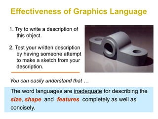
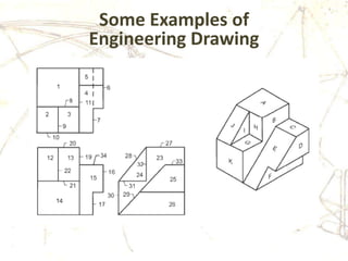
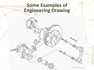
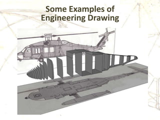
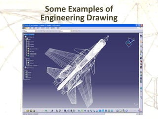
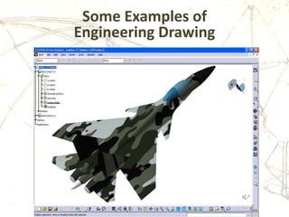
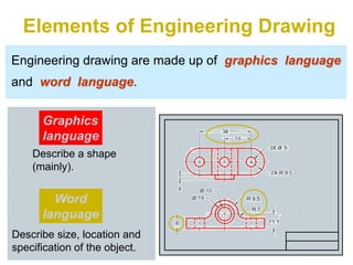
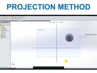
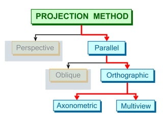
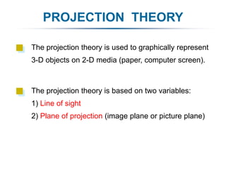
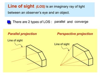
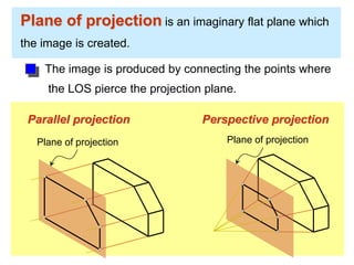
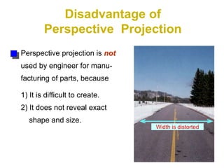
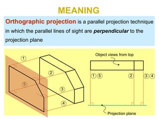
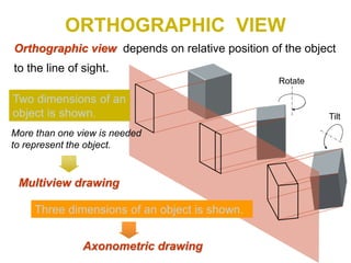
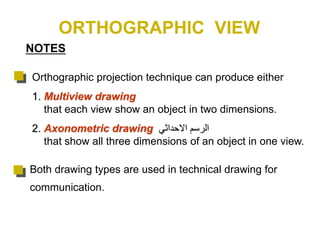
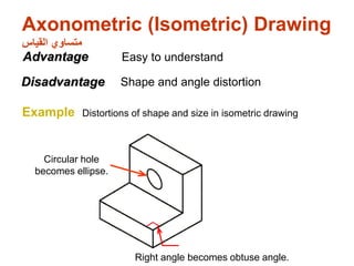
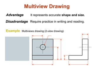
Lecture 5
Dr. Khaled Bakro
Engineering Drawing
Introduction to Engineering
and Profession Ethics
PART 4 – ENGINEERING GRAPHICAL COMMUNICATION
In this chapter: we will explain
16- ENGINEERING DRAWINGS AND SYMBOLS
Projection methods
Orthographic projection
Graphics language
Engineering drawing
GRAPHICS
LANGUAGE
1. Try to write a description of
this object.
2. Test your written description
by having someone attempt
to make a sketch from your
description.
Effectiveness of Graphics Language
The word languages are inadequate for describing the
size, shape and features completely as well as
concisely.
You can easily understand that …
Graphic language in “engineering application” use
lines to represent the surfaces, edges and contours
of objects.
A drawing can be done using freehand, instruments
or computer methods.
Composition of Graphic Language
The language is known as “drawing” or “drafting” .
Freehand drawing
The lines are sketched without using instruments other
than pencils and erasers.
Example
Instrument drawing
Instruments are used to draw straight lines, circles, and
curves concisely and accurately. Thus, the drawings are
usually made to scale.
Example
Why and What?
Why do we use sketching?
To make a quick, graphic representation of an
idea that can be easily communicated.
How do we represent objects so that others will
understand all essential features?
Use a graphics “language”. It has its own rules
and conventions so everybody can communicate.
How?
How do we represent a real object (3D) on paper
(2D)?
The graphics language has conventions for
different types of 2D “views.”
How do we develop the skill to read
representations made by other people?
Understand the “language” and practice using it.
Computer drawing
The drawings are usually made by commercial software
such as AutoCAD, solid works etc.
Example
Engineering Drawing
Engineering Drawing Definition
A language—a graphical language that
communicates ideas and information from one
mind to another.
Engineering Drawing Function
1. Information delivery
2. Preservation, archiving, use of information
3. Ways of thinking in the preparation of
information
Some Examples of
Engineering Drawing
Some Examples of
Engineering Drawing
Some Examples of
Engineering Drawing
Some Examples of
Engineering Drawing
Some Examples of
Engineering Drawing
Engineering Drawing
Elements of Engineering Drawing
Engineering drawing are made up of graphics language
and word language.
Graphics
language
Describe a shape
(mainly).
Word
language
Describe size, location and
specification of the object.
Basic Knowledge for Drafting
Graphics
language
Word
language
Line
types
Geometric
construction Lettering
Projection
method
Knowledge and Skills Require
Graphics
language
Word
language
Dimensions & Notes
Visualization is the ability to mentally picture things that do not exists.
VisualizationUsing line types
Geometric
construction
Projection
method
Engineering Drawing
PROJECTION
METHOD
PROJECTION METHOD
PROJECTION METHOD
Perspective
Oblique Orthographic
Axonometric Multiview
Parallel
PROJECTION THEORY
The projection theory is based on two variables:
1) Line of sight
2) Plane of projection (image plane or picture plane)
The projection theory is used to graphically represent
3-D objects on 2-D media (paper, computer screen).
Line of sight (LOS) is an imaginary ray of light
between an observer’s eye and an object.
Line of sight
Parallel projection
Line of sight
Perspective projection
There are 2 types of LOS : parallel convergeand
Plane of projection is an imaginary flat plane which
the image is created.
The image is produced by connecting the points where
the LOS pierce the projection plane.
Parallel projection Perspective projection
Plane of projection Plane of projection
Disadvantage of
Perspective Projection
Perspective projection is not
used by engineer for manu-
facturing of parts, because
1) It is difficult to create.
2) It does not reveal exact
shape and size.
Width is distorted
Orthographic
Projection
5
Orthographic projection is a parallel projection technique
in which the parallel lines of sight are perpendicular to the
projection plane
MEANING
Object views from top
Projection plane
1
2
3
4
51 2 3 4
ORTHOGRAPHIC VIEW
Orthographic view depends on relative position of the object
to the line of sight.
Two dimensions of an
object is shown.
Three dimensions of an object is shown.
Rotate
Tilt
More than one view is needed
to represent the object.
Multiview drawing
Axonometric drawing
Orthographic Projection
Orthographic projection technique can produce either
1. Multiview drawing
that each view show an object in two dimensions.
2. Axonometric drawing ‫االحداثي‬ ‫الرسم‬
that show all three dimensions of an object in one view.
Both drawing types are used in technical drawing for
communication.
NOTES
ORTHOGRAPHIC VIEW
Axonometric (Isometric) Drawing
‫القياس‬ ‫متساوي‬
Easy to understand
Right angle becomes obtuse angle.
Circular hole
becomes ellipse.
Distortions of shape and size in isometric drawing
Advantage
Disadvantage Shape and angle distortion
Example
Multiview Drawing
It represents accurate shape and size.Advantage
Disadvantage Require practice in writing and reading.
Multiviews drawing (2-view drawing)Example
SUMMARY
• You should have a good understanding of the
importance of engineering drawings in conveying
information to other engineers.
• You should understand what is meant by orthographic
views, isometric drawing, and solid modeling.
• You should understand the basic rules required for an
engineering drawing, including showing dimensions,
specifying material size, and indicating finished
surfaces.
• You should know when to use isometric views and
sectional views.

Introduction to Engineering and Profession Ethics Lecture5-Engineering Drawing-Dr.Khaled Bakro د. خالد بكرو

  • 1.
    Lecture 5 Dr. KhaledBakro Engineering Drawing Introduction to Engineering and Profession Ethics
  • 2.
    PART 4 –ENGINEERING GRAPHICAL COMMUNICATION In this chapter: we will explain 16- ENGINEERING DRAWINGS AND SYMBOLS Projection methods Orthographic projection Graphics language Engineering drawing
  • 3.
  • 4.
    1. Try towrite a description of this object. 2. Test your written description by having someone attempt to make a sketch from your description. Effectiveness of Graphics Language The word languages are inadequate for describing the size, shape and features completely as well as concisely. You can easily understand that …
  • 5.
    Graphic language in“engineering application” use lines to represent the surfaces, edges and contours of objects. A drawing can be done using freehand, instruments or computer methods. Composition of Graphic Language The language is known as “drawing” or “drafting” .
  • 6.
    Freehand drawing The linesare sketched without using instruments other than pencils and erasers. Example
  • 7.
    Instrument drawing Instruments areused to draw straight lines, circles, and curves concisely and accurately. Thus, the drawings are usually made to scale. Example
  • 8.
    Why and What? Whydo we use sketching? To make a quick, graphic representation of an idea that can be easily communicated. How do we represent objects so that others will understand all essential features? Use a graphics “language”. It has its own rules and conventions so everybody can communicate.
  • 9.
    How? How do werepresent a real object (3D) on paper (2D)? The graphics language has conventions for different types of 2D “views.” How do we develop the skill to read representations made by other people? Understand the “language” and practice using it.
  • 10.
    Computer drawing The drawingsare usually made by commercial software such as AutoCAD, solid works etc. Example
  • 11.
  • 12.
    Engineering Drawing Definition Alanguage—a graphical language that communicates ideas and information from one mind to another.
  • 13.
    Engineering Drawing Function 1.Information delivery 2. Preservation, archiving, use of information 3. Ways of thinking in the preparation of information
  • 14.
  • 15.
  • 16.
  • 17.
  • 18.
  • 19.
  • 20.
    Elements of EngineeringDrawing Engineering drawing are made up of graphics language and word language. Graphics language Describe a shape (mainly). Word language Describe size, location and specification of the object.
  • 21.
    Basic Knowledge forDrafting Graphics language Word language Line types Geometric construction Lettering Projection method
  • 22.
    Knowledge and SkillsRequire Graphics language Word language Dimensions & Notes Visualization is the ability to mentally picture things that do not exists. VisualizationUsing line types Geometric construction Projection method Engineering Drawing
  • 23.
  • 24.
  • 25.
  • 26.
    PROJECTION THEORY The projectiontheory is based on two variables: 1) Line of sight 2) Plane of projection (image plane or picture plane) The projection theory is used to graphically represent 3-D objects on 2-D media (paper, computer screen).
  • 27.
    Line of sight(LOS) is an imaginary ray of light between an observer’s eye and an object. Line of sight Parallel projection Line of sight Perspective projection There are 2 types of LOS : parallel convergeand
  • 28.
    Plane of projectionis an imaginary flat plane which the image is created. The image is produced by connecting the points where the LOS pierce the projection plane. Parallel projection Perspective projection Plane of projection Plane of projection
  • 29.
    Disadvantage of Perspective Projection Perspectiveprojection is not used by engineer for manu- facturing of parts, because 1) It is difficult to create. 2) It does not reveal exact shape and size. Width is distorted
  • 30.
  • 31.
    5 Orthographic projection isa parallel projection technique in which the parallel lines of sight are perpendicular to the projection plane MEANING Object views from top Projection plane 1 2 3 4 51 2 3 4
  • 32.
    ORTHOGRAPHIC VIEW Orthographic viewdepends on relative position of the object to the line of sight. Two dimensions of an object is shown. Three dimensions of an object is shown. Rotate Tilt More than one view is needed to represent the object. Multiview drawing Axonometric drawing
  • 33.
  • 34.
    Orthographic projection techniquecan produce either 1. Multiview drawing that each view show an object in two dimensions. 2. Axonometric drawing ‫االحداثي‬ ‫الرسم‬ that show all three dimensions of an object in one view. Both drawing types are used in technical drawing for communication. NOTES ORTHOGRAPHIC VIEW
  • 35.
    Axonometric (Isometric) Drawing ‫القياس‬‫متساوي‬ Easy to understand Right angle becomes obtuse angle. Circular hole becomes ellipse. Distortions of shape and size in isometric drawing Advantage Disadvantage Shape and angle distortion Example
  • 36.
    Multiview Drawing It representsaccurate shape and size.Advantage Disadvantage Require practice in writing and reading. Multiviews drawing (2-view drawing)Example
  • 37.
    SUMMARY • You shouldhave a good understanding of the importance of engineering drawings in conveying information to other engineers. • You should understand what is meant by orthographic views, isometric drawing, and solid modeling. • You should understand the basic rules required for an engineering drawing, including showing dimensions, specifying material size, and indicating finished surfaces. • You should know when to use isometric views and sectional views.