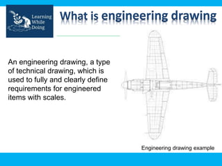
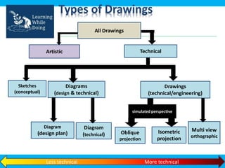
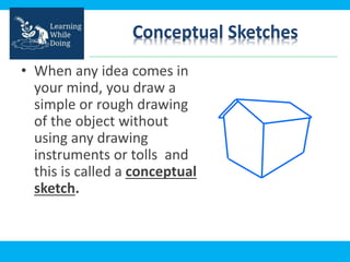
Engineering Drawing
What is engineering drawing
An engineering drawing, a type
of technical drawing, which is
used to fully and clearly define
requirements for engineered
items with scales.
Engineering drawing example
Types of Drawings
Artistic
Sketches
(conceptual)
Diagrams
(design & technical)
Drawings
(technical/engineering)
Diagram
(design plan)
All Drawings
Technical
Diagram
(technical)
simulated perspective
Oblique
projection
Isometric
projection
Multi view
orthographic
Less technical More technical
Conceptual Sketches
• When any idea comes in
your mind, you draw a
simple or rough drawing
of the object without
using any drawing
instruments or tolls and
this is called a conceptual
sketch.
Importance of Engineering
Drawings
• Helps as a reference to workers, technicians or
architects.
• Easy to understand : Since a picture is easiest
method than thousand words, a technical drawing is
a much more effective tool for engineers than a
written plan.
• Engineering drawings is used in all engineering
fields, including, but not limited to, civil engineering,
electrical engineering, mechanical engineering and
architecture.
Sketch Vs Engineering drawing
• Sketch: made without drafting tools... Just pencil and
paper. Scale is approximate, not accurate, but the
sketch should still look like the object.
• Engineering Drawing: Made with drafting tools...
Ruler, set squares, protractor and compass. Scale
should be accurate and the drawing carefully made.
Projection
• If straight lines are drawn from various points on
the contour (A contour line is a imaginary line
which connects points of equal elevation) of an
object to meet a plane, the object is said to be
projected on that plane.
• The figure formed by joining, in correct sequence,
the points at which these lines meet the plane, is
called the projection of the object.
• The lines from the object to the plane are called
projectors.
Projection
Projection Types
• Orthographic projection
• Isometric projection
Orthographic projection
• Orthographic Projection is a way of drawing an
3D object from different directions.
• Usually a front, side and plan view are drawn so
that a person looking at the drawing can see all
the important sides.
• Orthographic drawings are useful especially
when a design has been developed to a stage
whereby it is almost ready to manufacture.
Orthographic projection views
OBJECT
Orthographic projection
• As shown in the earlier slide, if an observer at
position ‘A’ moves to infinity, the projectors to
his eyes becomes parallel to the object and he
observes the same shape and size as that of the
object. The view so formed is known as the
orthographic projection.
• Similarly, the parallel projectors shall form the
pictures on the respective picture planes from
the positions B and C.
Isometric Projection
• Isometric projection is a method for visually
representing three-dimensional objects in two
dimensions in technical and engineering drawings
• Isometric drawings consist of two-dimensional
drawings that are tilted at some angle to expose
other views and give the viewer the illusion that
what he or she is viewing is a three-dimensional
drawing.
An Isometric Drawing
Comparison of Projections
Orthographic Isometric
Used for : Drafting, maps, floor
plans
Technical drawings, drafting,
conceptual sketches (sometimes)
Used for : Conceptual sketches,
technical drawings (sometimes)
Orthographic is a set of 3 Plane
Projections
Isometric is a 3-D sketch
Diagrams
• Diagrams are simplified versions of a drawing.
Diagrams show how an object works, not
necessarily how it looks.
• Diagrams often use symbols rather than actual
pictures to represent things.
A Circuit Diagram
– Doesn’t show what the circuit looks like, but tells
an electrician how its all connected.

Engineering_Engineering_Drawing_Engineer.ppt

  • 1.
  • 2.
    What is engineeringdrawing An engineering drawing, a type of technical drawing, which is used to fully and clearly define requirements for engineered items with scales. Engineering drawing example
  • 3.
    Types of Drawings Artistic Sketches (conceptual) Diagrams (design& technical) Drawings (technical/engineering) Diagram (design plan) All Drawings Technical Diagram (technical) simulated perspective Oblique projection Isometric projection Multi view orthographic Less technical More technical
  • 4.
    Conceptual Sketches • Whenany idea comes in your mind, you draw a simple or rough drawing of the object without using any drawing instruments or tolls and this is called a conceptual sketch.
  • 5.
    Importance of Engineering Drawings •Helps as a reference to workers, technicians or architects. • Easy to understand : Since a picture is easiest method than thousand words, a technical drawing is a much more effective tool for engineers than a written plan. • Engineering drawings is used in all engineering fields, including, but not limited to, civil engineering, electrical engineering, mechanical engineering and architecture.
  • 6.
    Sketch Vs Engineeringdrawing • Sketch: made without drafting tools... Just pencil and paper. Scale is approximate, not accurate, but the sketch should still look like the object. • Engineering Drawing: Made with drafting tools... Ruler, set squares, protractor and compass. Scale should be accurate and the drawing carefully made.
  • 7.
    Projection • If straightlines are drawn from various points on the contour (A contour line is a imaginary line which connects points of equal elevation) of an object to meet a plane, the object is said to be projected on that plane. • The figure formed by joining, in correct sequence, the points at which these lines meet the plane, is called the projection of the object. • The lines from the object to the plane are called projectors.
  • 8.
  • 9.
    Projection Types • Orthographicprojection • Isometric projection
  • 10.
    Orthographic projection • OrthographicProjection is a way of drawing an 3D object from different directions. • Usually a front, side and plan view are drawn so that a person looking at the drawing can see all the important sides. • Orthographic drawings are useful especially when a design has been developed to a stage whereby it is almost ready to manufacture.
  • 11.
  • 12.
    Orthographic projection • Asshown in the earlier slide, if an observer at position ‘A’ moves to infinity, the projectors to his eyes becomes parallel to the object and he observes the same shape and size as that of the object. The view so formed is known as the orthographic projection. • Similarly, the parallel projectors shall form the pictures on the respective picture planes from the positions B and C.
  • 13.
    Isometric Projection • Isometricprojection is a method for visually representing three-dimensional objects in two dimensions in technical and engineering drawings • Isometric drawings consist of two-dimensional drawings that are tilted at some angle to expose other views and give the viewer the illusion that what he or she is viewing is a three-dimensional drawing.
  • 14.
  • 15.
    Comparison of Projections OrthographicIsometric Used for : Drafting, maps, floor plans Technical drawings, drafting, conceptual sketches (sometimes) Used for : Conceptual sketches, technical drawings (sometimes) Orthographic is a set of 3 Plane Projections Isometric is a 3-D sketch
  • 16.
    Diagrams • Diagrams aresimplified versions of a drawing. Diagrams show how an object works, not necessarily how it looks. • Diagrams often use symbols rather than actual pictures to represent things.
  • 17.
    A Circuit Diagram –Doesn’t show what the circuit looks like, but tells an electrician how its all connected.