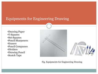
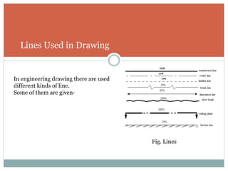
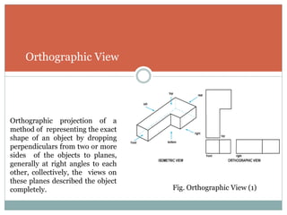
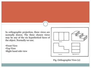
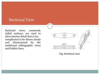
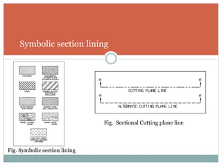
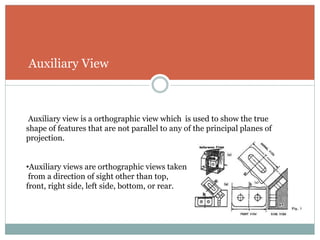
This document provides an introduction to engineering drawing. It outlines the objectives of learning engineering drawing such as understanding basic concepts, necessary equipment, lines, dimensions, orthographic views, sectional views, and auxiliary views. It defines engineering drawing as using geometric shapes, lines and dimensions to convey design and manufacturing information for machines, structures or systems. The key equipment used for engineering drawing are listed. Orthographic, sectional and auxiliary views are described as the main types of graphical projections used. Sectional views show interior details, auxiliary views show features not parallel to common planes, and orthographic views use front, top and side views.
G R OU P M E M B E R S :
1 . M D . R O K I B U L H A Q U E ( 2 0 1 4 3 3 4 0 6 2 )
2 . S H A R I F M U K T A D I R H O S S A I N C H O W D H U R Y ( 2 0 1 4 3 3 4 0 6 1 )
3 . S A T Y E N M A Z U M D E R ( 2 0 1 4 3 3 4 0 6 3 )
Welcome
to
Presentation of Group “P”
3.
Objectives
To getprimary concepts of Engineering Drawing.
To know the necessity of Engineering Drawing.
To know about the equipments used in Engineering Drawing.
To know various signs, lines and dimensions.
To know about Orthogonal view.
To know about Sectional view.
To know about Auxiliary view.
4.
Introductions:
Drawing is thebasic from of communication in technology and Industry. It expresses
ideas and conveys specific information by means on geometric shapes lines and
dimensions. It is a universal language that improves communications and eliminates
costly errors of interpretation with drawing conventions. Engineering drawing is the main
method of communication between all parsons concerned with the design and
manufacturing of components.
5.
What is EngineeringDrawing??
A graphical language to convey graphically the ideas and
information necessary for the construction or analysis of
machines, structures, or systems by geometric shapes
lines and dimensions.
6.
Equipments for EngineeringDrawing
•Drawing Paper
•T-Squares
•Set-Squares
•Pencil Sharpeners
•Erasers
•Pencil Compasses
•Dividers
•Drawing Pencil
•Scotch Tape
Fig. Equipments for Engineering Drawing
7.
Lines Used inDrawing
In engineering drawing there are used
different kinds of line.
Some of them are given-
Fig. Lines
8.
Type of GraphicalProjection
Today We are describing three types of projection
1. Orthographic View.
2. Sectional View.
3. Auxiliary View
9.
Orthographic View
Orthographic projectionof a
method of representing the exact
shape of an object by dropping
perpendiculars from two or more
sides of the objects to planes,
generally at right angles to each
other, collectively, the views on
these planes described the object
completely. Fig. Orthographic View (1)
10.
In orthographic projection,three views are
normally drawn. The three chosen views
may be any of the six hypothetical faces of
the object. Normally we use;
•Front View
•Top View
•Right hand side view
Fig. Orthographic View (2)
11.
Sectional View
Sectional views,commonly
called sections, are used to
show interior detail that is too
complicated to be shown clearly
and dimensioned by the
traditional orthographic views
and hidden lines.
Fig. Sectional view
12.
Overview of SectionalProjection
• Sections are used to show interior details clearly.
• A cutting-plane line shows where object was cut to obtain the section view.
• Cross hatching in the section view shows the solid surface of the object which
were cut through to produce the section.
• Section views may replace standard views.
Auxiliary View
Auxiliary viewis a orthographic view which is used to show the true
shape of features that are not parallel to any of the principal planes of
projection.
•Auxiliary views are orthographic views taken
from a direction of sight other than top,
front, right side, left side, bottom, or rear.
15.
Purpose of AuxiliaryView
Purposes of Auxiliary Views
•Show the true size and shape of a surface.
•Show the true angle between two surface.
•To give clear view of that plane which is not parallel the common planes.