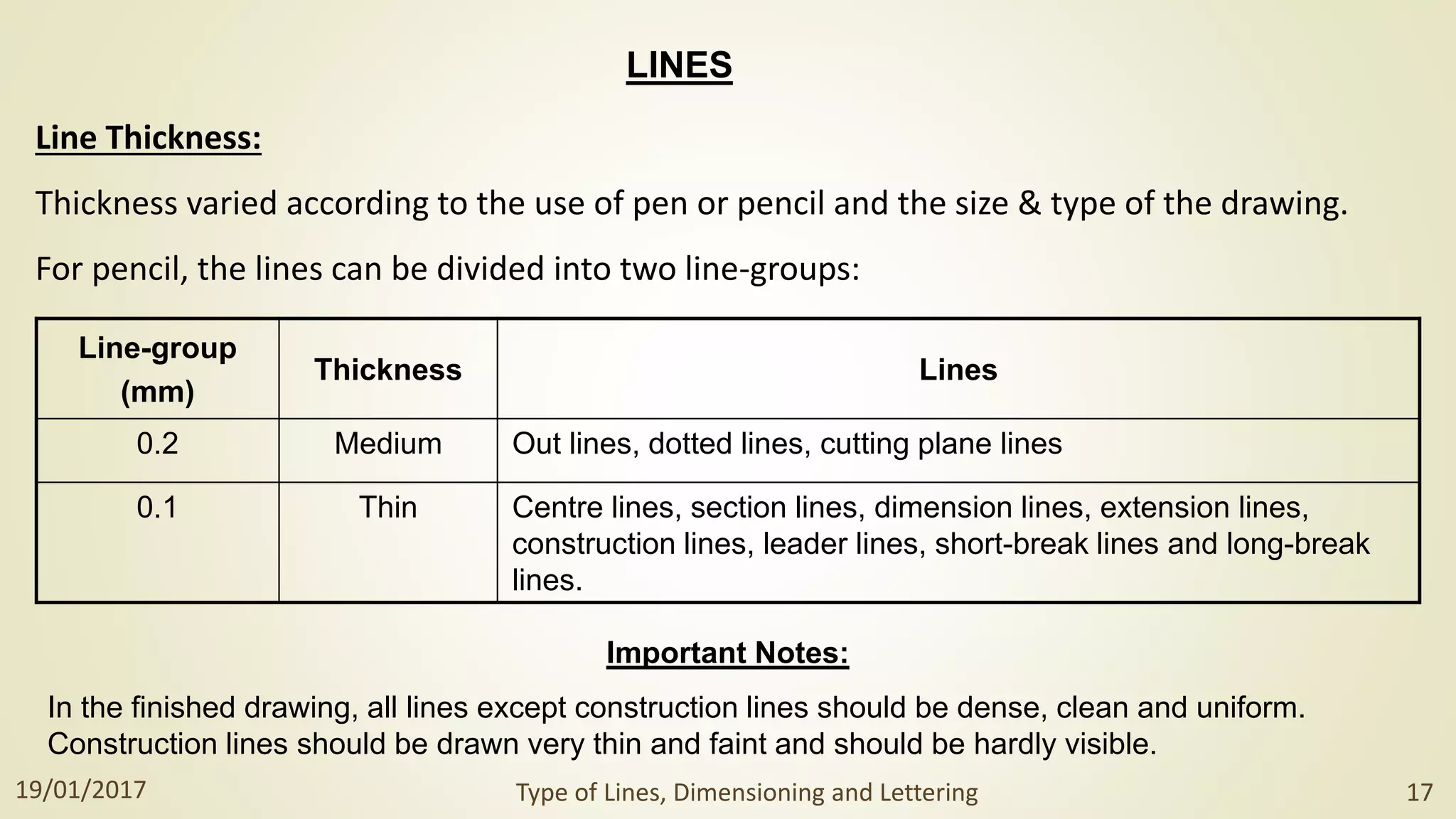
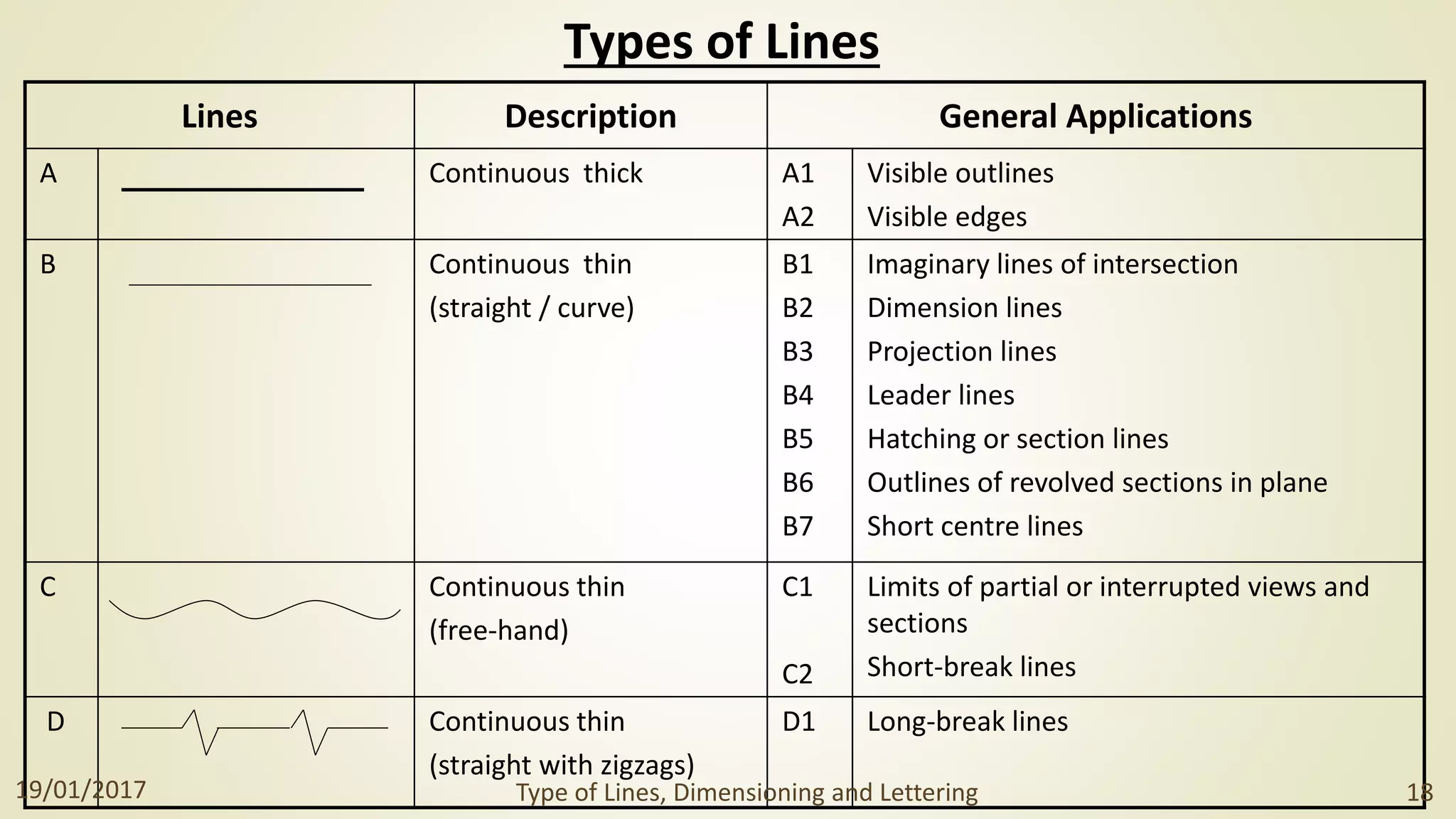
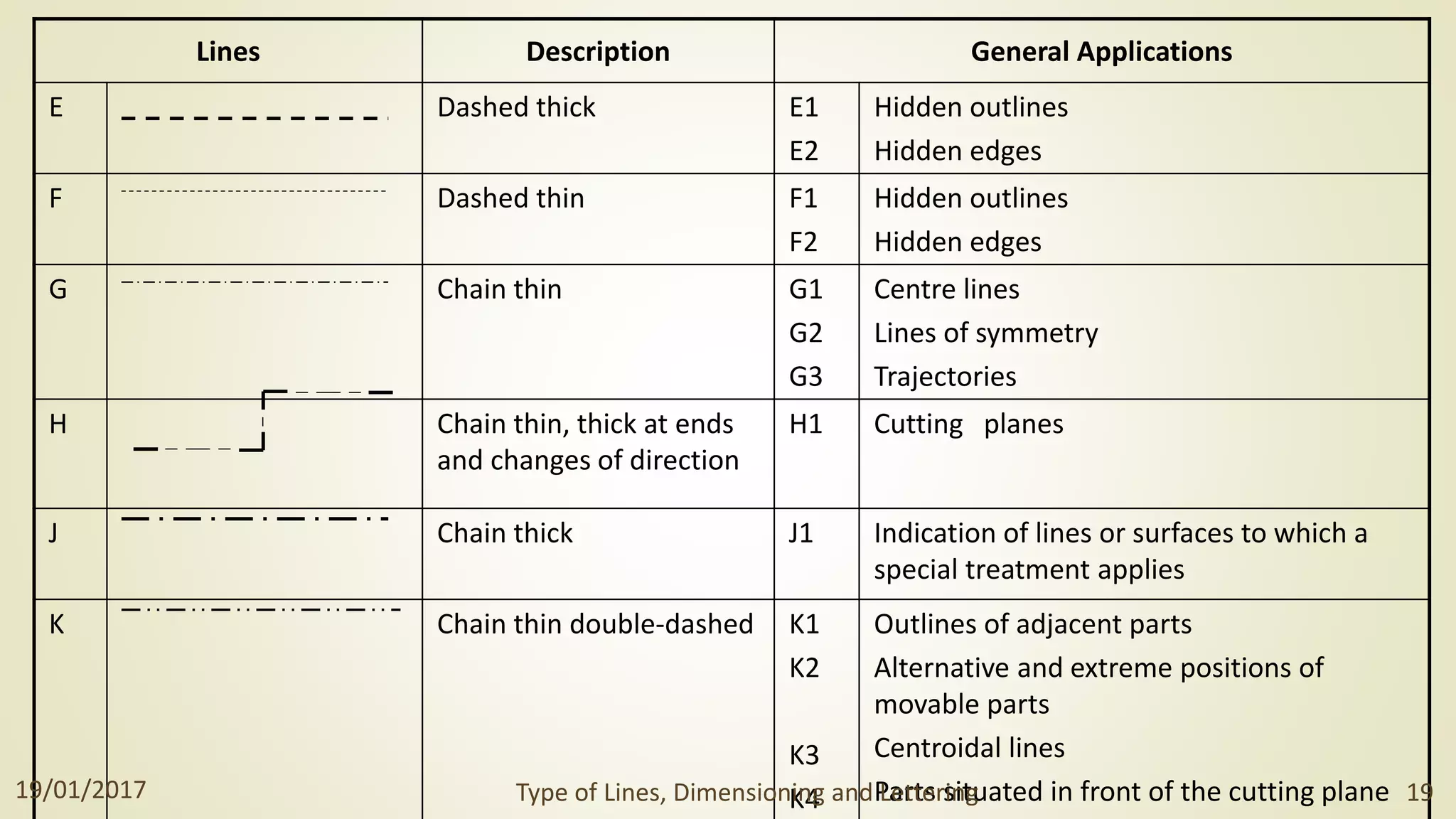
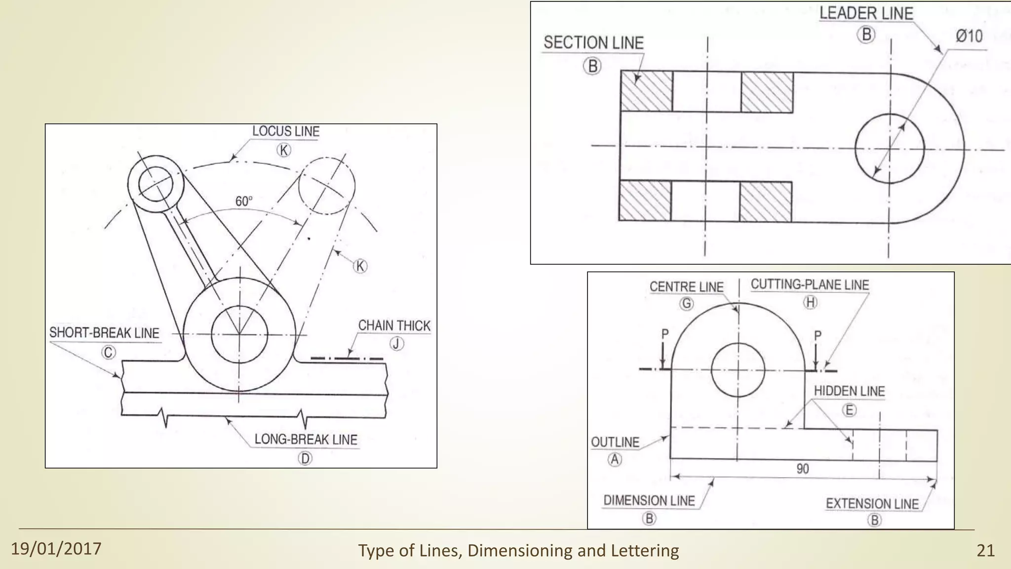
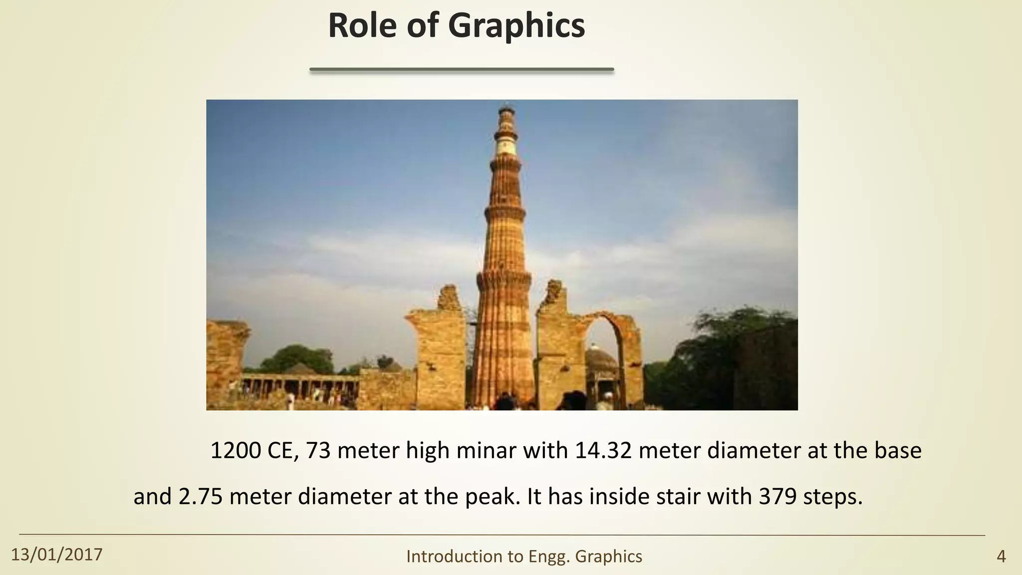
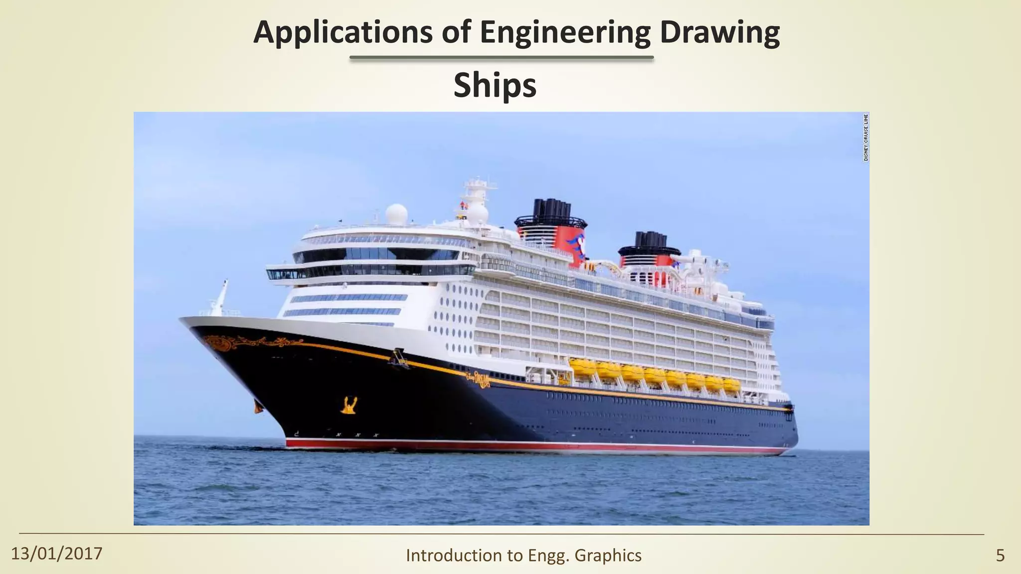
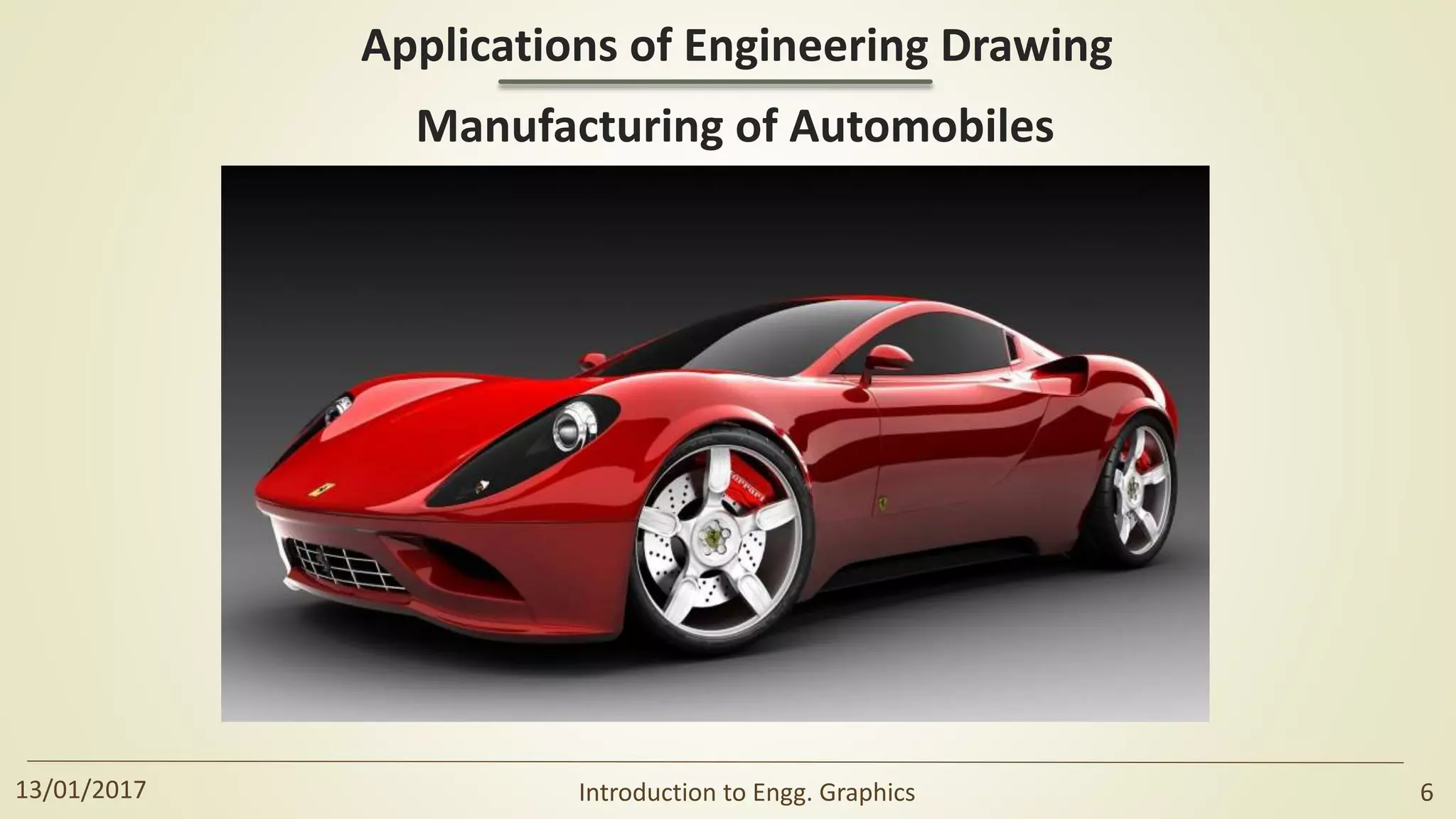
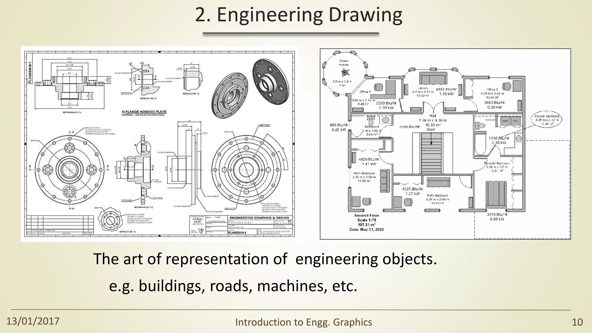
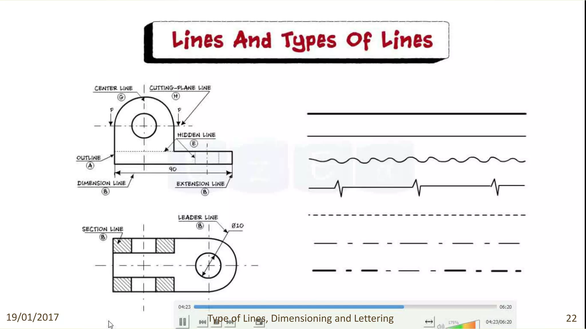
An engineering drawing is a technical drawing that clearly defines and communicates a design. It is used for collaboration, procurement, manufacturing, and quality control. The document discusses the role of graphics in visualization, communication, and documentation. It also provides examples of engineering drawing applications in construction, manufacturing, and ships. Key aspects like types of lines, dimensioning, lettering, and scales are explained.
Download link: https://www.researchgate.net/publication/318852873_Engineering_Drawing_-_I
DOI: 10.13140/RG.2.2.22512.56328
An engineering drawing is a type of technical drawing, used to fully and clearly define requirements for engineered items, and is usually created in accordance with standardized conventions for layout, nomenclature, interpretation, appearance size, etc.
Its purpose is to accurately and unambiguously capture all the geometric features of a product or a component. The end goal of an engineering drawing is to convey all the required information that will allow a manufacturer to produce that component.
Scales
THIS SLIDE CONTAINS WHOLE SYLLABUS OF ENGINEERING DRAWING/GRAPHICS. IT IS THE MOST SIMPLE AND INTERACTIVE WAY TO LEARN ENGINEERING DRAWING.SYLLABUS IS RELATED TO rajiv gandhi proudyogiki vishwavidyalaya / rajiv gandhi TECHNICAL UNIVERSITY ,BHOPAL.
check it out: http://goo.gl/vqNk7m
CADmantra Technologies pvt. Ltd. is a CAD Training institute specilized in producing quality and high standard education and training. We are providing a perfact institute for the students intersted in CAD courses CADmantra is established by a group of engineers to devlop good training system in the field of CAD/CAM/CAE, these courses are widely accepted worldwide.
#catiatraining
#ANSYS #CRE-O
#hypermesh
#Automobileworkshops
#enginedevelopment
#autocad
#sketching
introduction of engineering graphics ,projection of points,lines,planes,solids,section of solids,development of surfaces,isometric projection,perspective projection
Basics of engineering drawing by Rishabh NatholiaRISHABH NATHOLIA
This is my work to make sure it is easy to understand the basic of Mechanical Engineer Drawing.It is a made for all and a quick bite to the very basics of engineering drawing. This data will also help the students to score more in their subjects. This will also help on design sector interviews.
Introduction,
Role of Engineering Drawing,
Drawing Instrument and Aids,
Drawing Board,
Mini-Draughter,
Instrument Box,
Set of Scales,
French Curves,
Templates,
Pencils,
Download the original presentation for animation and clear understanding. This Presentation describes the concepts of Engineering Drawing of VTU Syllabus. However same can also be used for learning drawing concepts. Please write to me for suggestions and criticisms here: hareeshang@gmail.com or visit this website for more details: www.hareeshang.wikifoundry.com.
Dimensioning, scales, lines and multiple projectionsAkash Patel
Fiction is a form of narrative, one of the four rhetorical modes of discourse. Fiction-writing also has modes for fiction-writing: action, exposition, description, dialogue, summary, and transition (Morrell 2006, p. 127). Author Peter Selgin refers to methods, including action, dialogue, thoughts, summary, scene, and description (Selgin 2007, p. 38). Currently, there is no consensus within the writing community regarding the number and composition of fiction-writing modes and their uses.
Description is the fiction-writing mode for transmitting a mental image of the particulars of a story. Together with dialogue, narration, exposition, and summarization, description is one of the most widely recognized of the fiction-writing modes. As stated in Writing from A to Z, edited by Kirk Polking, description is more than the amassing of details; it is bringing something to life by carefully choosing and arranging words and phrases to produce the desired effect (Polking 1990, p. 106). The most appropriate and effective techniques for presenting description are a matter of ongoing discussion among writers and writing coaches.Fiction is a form of narrative, one of the four rhetorical modes of discourse. Fiction-writing also has modes for fiction-writing: action, exposition, description, dialogue, summary, and transition (Morrell 2006, p. 127). Author Peter Selgin refers to methods, including action, dialogue, thoughts, summary, scene, and description (Selgin 2007, p. 38). Currently, there is no consensus within the writing community regarding the number and composition of fiction-writing modes and their uses.
Description is the fiction-writing mode for transmitting a mental image of the particulars of a story. Together with dialogue, narration, exposition, and summarization, description is one of the most widely recognized of the fiction-w
Similar to Introduction to engineering graphics (20)
Final project report on grocery store management system..pdfKamal Acharya
In today’s fast-changing business environment, it’s extremely important to be able to respond to client needs in the most effective and timely manner. If your customers wish to see your business online and have instant access to your products or services.
Online Grocery Store is an e-commerce website, which retails various grocery products. This project allows viewing various products available enables registered users to purchase desired products instantly using Paytm, UPI payment processor (Instant Pay) and also can place order by using Cash on Delivery (Pay Later) option. This project provides an easy access to Administrators and Managers to view orders placed using Pay Later and Instant Pay options.
In order to develop an e-commerce website, a number of Technologies must be studied and understood. These include multi-tiered architecture, server and client-side scripting techniques, implementation technologies, programming language (such as PHP, HTML, CSS, JavaScript) and MySQL relational databases. This is a project with the objective to develop a basic website where a consumer is provided with a shopping cart website and also to know about the technologies used to develop such a website.
This document will discuss each of the underlying technologies to create and implement an e- commerce website.
About
Indigenized remote control interface card suitable for MAFI system CCR equipment. Compatible for IDM8000 CCR. Backplane mounted serial and TCP/Ethernet communication module for CCR remote access. IDM 8000 CCR remote control on serial and TCP protocol.
• Remote control: Parallel or serial interface.
• Compatible with MAFI CCR system.
• Compatible with IDM8000 CCR.
• Compatible with Backplane mount serial communication.
• Compatible with commercial and Defence aviation CCR system.
• Remote control system for accessing CCR and allied system over serial or TCP.
• Indigenized local Support/presence in India.
• Easy in configuration using DIP switches.
Technical Specifications
Indigenized remote control interface card suitable for MAFI system CCR equipment. Compatible for IDM8000 CCR. Backplane mounted serial and TCP/Ethernet communication module for CCR remote access. IDM 8000 CCR remote control on serial and TCP protocol.
Key Features
Indigenized remote control interface card suitable for MAFI system CCR equipment. Compatible for IDM8000 CCR. Backplane mounted serial and TCP/Ethernet communication module for CCR remote access. IDM 8000 CCR remote control on serial and TCP protocol.
• Remote control: Parallel or serial interface
• Compatible with MAFI CCR system
• Copatiable with IDM8000 CCR
• Compatible with Backplane mount serial communication.
• Compatible with commercial and Defence aviation CCR system.
• Remote control system for accessing CCR and allied system over serial or TCP.
• Indigenized local Support/presence in India.
Application
• Remote control: Parallel or serial interface.
• Compatible with MAFI CCR system.
• Compatible with IDM8000 CCR.
• Compatible with Backplane mount serial communication.
• Compatible with commercial and Defence aviation CCR system.
• Remote control system for accessing CCR and allied system over serial or TCP.
• Indigenized local Support/presence in India.
• Easy in configuration using DIP switches.
NO1 Uk best vashikaran specialist in delhi vashikaran baba near me online vas...Amil Baba Dawood bangali
Contact with Dawood Bhai Just call on +92322-6382012 and we'll help you. We'll solve all your problems within 12 to 24 hours and with 101% guarantee and with astrology systematic. If you want to take any personal or professional advice then also you can call us on +92322-6382012 , ONLINE LOVE PROBLEM & Other all types of Daily Life Problem's.Then CALL or WHATSAPP us on +92322-6382012 and Get all these problems solutions here by Amil Baba DAWOOD BANGALI
#vashikaranspecialist #astrologer #palmistry #amliyaat #taweez #manpasandshadi #horoscope #spiritual #lovelife #lovespell #marriagespell#aamilbabainpakistan #amilbabainkarachi #powerfullblackmagicspell #kalajadumantarspecialist #realamilbaba #AmilbabainPakistan #astrologerincanada #astrologerindubai #lovespellsmaster #kalajaduspecialist #lovespellsthatwork #aamilbabainlahore#blackmagicformarriage #aamilbaba #kalajadu #kalailam #taweez #wazifaexpert #jadumantar #vashikaranspecialist #astrologer #palmistry #amliyaat #taweez #manpasandshadi #horoscope #spiritual #lovelife #lovespell #marriagespell#aamilbabainpakistan #amilbabainkarachi #powerfullblackmagicspell #kalajadumantarspecialist #realamilbaba #AmilbabainPakistan #astrologerincanada #astrologerindubai #lovespellsmaster #kalajaduspecialist #lovespellsthatwork #aamilbabainlahore #blackmagicforlove #blackmagicformarriage #aamilbaba #kalajadu #kalailam #taweez #wazifaexpert #jadumantar #vashikaranspecialist #astrologer #palmistry #amliyaat #taweez #manpasandshadi #horoscope #spiritual #lovelife #lovespell #marriagespell#aamilbabainpakistan #amilbabainkarachi #powerfullblackmagicspell #kalajadumantarspecialist #realamilbaba #AmilbabainPakistan #astrologerincanada #astrologerindubai #lovespellsmaster #kalajaduspecialist #lovespellsthatwork #aamilbabainlahore #Amilbabainuk #amilbabainspain #amilbabaindubai #Amilbabainnorway #amilbabainkrachi #amilbabainlahore #amilbabaingujranwalan #amilbabainislamabad
Water scarcity is the lack of fresh water resources to meet the standard water demand. There are two type of water scarcity. One is physical. The other is economic water scarcity.
Overview of the fundamental roles in Hydropower generation and the components involved in wider Electrical Engineering.
This paper presents the design and construction of hydroelectric dams from the hydrologist’s survey of the valley before construction, all aspects and involved disciplines, fluid dynamics, structural engineering, generation and mains frequency regulation to the very transmission of power through the network in the United Kingdom.
Author: Robbie Edward Sayers
Collaborators and co editors: Charlie Sims and Connor Healey.
(C) 2024 Robbie E. Sayers
1. What is an Engineering Drawing ?
“An Engineering Drawing is a technical (not artistic) drawing which
clearly defines and communicates a design to other interested parties.
Other parties may have an interest in design collaboration, procurement
/ purchasing, costing, manufacturing, quality control, marketing,
handling / packaging.”
13/01/2017 Introduction to Engg. Graphics 1
3. Role of Graphics
• Visualization
• Communication
• Documentation
13/01/2017 Introduction to Engg. Graphics 3
4. Role of Graphics
1200 CE, 73 meter high minar with 14.32 meter diameter at the base
and 2.75 meter diameter at the peak. It has inside stair with 379 steps.
13/01/2017 Introduction to Engg. Graphics 4
8. Introduction
Drawing:
The way of conveying the ideas through the systematic lines on the
paper. The art of representation of an object by systematic lines on a paper.
Classification:
1. Artistic Drawing
2. Engineering Drawing
13/01/2017 Introduction to Engg. Graphics 8
9. 1. Artistic Drawing
The art of representation of an object by the artist by his imagination or by
keeping the object before him.
e.g. paintings, cinema posters, advertisement boards, etc.
13/01/2017 Introduction to Engg. Graphics 9
10. 2. Engineering Drawing
The art of representation of engineering objects.
e.g. buildings, roads, machines, etc.
13/01/2017 Introduction to Engg. Graphics 10
11. Drawing Instruments
1. Drawing Board
2. Drawing Sheet
3. Drawing Sheet Holder
4. Set-squares – 45o and 30o – 60o
5. Large size Compass
6. Small bow Compass
7. Large size Divider
8. Small bow Divider
9. Scales – 6” and 12”
10. Protractor
11. French Curve
12. Drawing Pencils – H, 2H, HB
13. Sand Paper
14. Eraser (Rubber)
15. Drawing Pins and Clips
16. Cello Tape
17. Duster or Handkerchief
18. Drafting Machine / Mini Drafter
19. Sketch Book (Medium size)
20. Roller Scale
21. Pencil Sharpener
22. Sheet Folder
13/01/2017 Introduction to Engg. Graphics 11
13. Use of Drawing Instruments
13/01/2017 Introduction to Engg. Graphics 13
14. Layout of Drawing Sheet
Title Block
30 20
2020
All the dimensions are in millimeters.
150
50
19/01/2017 Type of Lines, Dimensioning and Lettering 14
15. SHEET NO.: 01
CHECKED BY:
NAME:
ROLL NO.:
SEM. & SEC.:
SUB. DATE:
GRADE:
LINES
&
LETTERING
NOTES:
All the dimensions are in millimeters.
Name and Roll No. should be written by ink-pen.
50 50 50
10
20101010
10101010
Title Block (Sample)
19/01/2017 Type of Lines, Dimensioning and Lettering 15
17. LINES
Line Thickness:
Thickness varied according to the use of pen or pencil and the size & type of the drawing.
For pencil, the lines can be divided into two line-groups:
Line-group
(mm)
Thickness Lines
0.2 Medium Out lines, dotted lines, cutting plane lines
0.1 Thin Centre lines, section lines, dimension lines, extension lines,
construction lines, leader lines, short-break lines and long-break
lines.
Important Notes:
In the finished drawing, all lines except construction lines should be dense, clean and uniform.
Construction lines should be drawn very thin and faint and should be hardly visible.
19/01/2017 Type of Lines, Dimensioning and Lettering 17
18. Types of Lines
Lines Description General Applications
A Continuous thick A1
A2
Visible outlines
Visible edges
B Continuous thin
(straight / curve)
B1
B2
B3
B4
B5
B6
B7
Imaginary lines of intersection
Dimension lines
Projection lines
Leader lines
Hatching or section lines
Outlines of revolved sections in plane
Short centre lines
C Continuous thin
(free-hand)
C1
C2
Limits of partial or interrupted views and
sections
Short-break lines
D Continuous thin
(straight with zigzags)
D1 Long-break lines
19/01/2017 Type of Lines, Dimensioning and Lettering 18
19. Lines Description General Applications
E Dashed thick E1
E2
Hidden outlines
Hidden edges
F Dashed thin F1
F2
Hidden outlines
Hidden edges
G Chain thin G1
G2
G3
Centre lines
Lines of symmetry
Trajectories
H Chain thin, thick at ends
and changes of direction
H1 Cutting planes
J Chain thick J1 Indication of lines or surfaces to which a
special treatment applies
K Chain thin double-dashed K1
K2
K3
K4
Outlines of adjacent parts
Alternative and extreme positions of
movable parts
Centroidal lines
Parts situated in front of the cutting plane19/01/2017 Type of Lines, Dimensioning and Lettering 19
20. Application of various types of lines according to B.I.S.
PP
80o
G1
B5
B2
A1 J1
C1
D1
K2
G3
H1
E1
90
Ø10
B4
19/01/2017 Type of Lines, Dimensioning and Lettering 20
23. Lettering
Writing of titles, dimensions, notes and other important particulars on a drawing is lettering
Classification:
1. Single-stroke Letters:
The thickness of the line of the letter is obtained in one stroke of the pencil.
Recommended by B.I.S.
It has two types:
i. Vertical
ii. Inclined (slope 75o with the horizontal)
• The ratio of height to width varies but in most of the cases it is 6:5.
• Lettering is generally done in capital letters.
• The lower-case letters are generally used in architectural drawings.
19/01/2017 Type of Lines, Dimensioning and Lettering 23
24. • The spacing between two letters should not be necessarily equal.
• The letters should be so placed that they do not appear too close together
too much apart.
• The distance between the words must be uniform and at least equal to
the height of the letters.
• Lettering, except the dimension figures, should be underlined to make
them more prominent.
Size of Alphabets for Drawing:
Main titles -----------------------------------------6-8 mm
Sub titles ------------------------------------------3-6 mm
Notes, dimension figures, etc. ---------------3-5 mm
Drawing no. --------------------------------------10-12 mm
19/01/2017 Type of Lines, Dimensioning and Lettering 24
26. Dimensioning
The art of writing the various sizes or measurement on the finished drawing of an object.
Types of Dimensioning:
i. Size or Functional Dimensions (S):
It indicates sizes.
e.g. length, breadth, height, diameter, etc.
ii. Location or Datum Dimensions (L):
It shows location or exact position of various constructional details within the object.
L SL
S
L
19/01/2017 Type of Lines, Dimensioning and Lettering 26
27. Notations of Dimensioning
Symbol
Extension line Dimension line
2 Holes, Ø12
90
Arrow-head
Dimension figure
Leader
(at 30o,45o,60o)
Note
3X
X
Arrow-head19/01/2017 Type of Lines, Dimensioning and Lettering 27
28. 1. Dimension line:
Thin continuous line used to indicate the measurement.
2. Extension line:
Thin continuous line extending beyond the outline of the object.
3. Arrow-head:
Used to terminate the dimension line. Length : width ratio is 3:1.
Space filled up.
4. Note:
Gives information regarding specific operation relating to a feature.
5. Leader:
Thin continuous line connecting a note or a dimension figure with the feature to which it is applied.
Terminated by arrow-head or dot.
6. Symbol:
The representation of any object by some mark on the drawing.
It saves time and labour.19/01/2017 Type of Lines, Dimensioning and Lettering 28
29. Units of Dimensioning
As for as possible all dimensions should be given in millimeters omitting
the abbreviation mm.
If another unit is used, only the dimension figures should be written. But
a foot note such as ‘All the dimensions are in centimeters’ is inserted in a
prominent place near the title box.
e.g. 15.50
0.75 (Zero must precede the decimal point.)
15.50 ± .75 ( Zero is omitted.)
19/01/2017 Type of Lines, Dimensioning and Lettering 29
30. The ways of Placing the Dimensions in a Series
20 15 25
60
35
20
Chain Parallel
19/01/2017 Type of Lines, Dimensioning and Lettering 30
31. The ways of Placing the Dimensions in a Series
90
15
30 30
15
0 1560 45 30 30
Combined Progressive
19/01/2017 Type of Lines, Dimensioning and Lettering 31
32. 1. Chain Dimensioning:
Dimensions are arranged in a straight line.
2. Parallel Dimensioning:
All the dimensions are shown from a common base line.
The smaller dimension is placed nearer the view.
3. Combined Dimensioning:
Chain and parallel dimensioning used simultaneously.
4. Progressive Dimensioning:
One datum or surface is selected which reads as zero. All the dimensions are referred to that point
or surface.
The ways of Placing the Dimensions in a Series
19/01/2017 Type of Lines, Dimensioning and Lettering 32
33. Types of Dimensioning
1. Aligned System
In the aligned system the
dimensions are placed perpendicular to the
dimension line in such a way that it may be
read from bottom edge or right hand edge
of the drawing sheet.
2. Unidirectional System
In the unidirectional system, the
dimensions are so oriented such that they
can be read from the bottom of the
drawing.
19/01/2017 Type of Lines, Dimensioning and Lettering 33
34. Some Important Rules for Dimensioning
1. All the dimensions necessary for the correct functioning of the part should be expressed directly on
the drawing.
2. Every dimension should be given, but none should be given more than once.
3. A dimension should be placed on the view where its use is shown more clearly.
4. Dimensions should be placed outside the view, as for as possible.
5. Mutual crossing of dimension lines and dimensioning between hidden lines should be avoided. Also
it should not cross any other line of the drawing.
6. An outline or a centre line should never be used as a dimension line. A centre line may be
extended to serve as an extension line.
7. Aligned system of dimensioning is recommended.
8. Dimension lines should be drawn at least 8 mm away from the outlines and from each other.
9. The extension line should be extended by about 3 mm beyond the dimension line.
19/01/2017 Type of Lines, Dimensioning and Lettering 34
35. 15
10. When the space is too narrow, the arrow-head may be placed outside.
Also a dot may be used to replace an arrow-head.
11. The various methods of dimensioning different sizes of circles are as
follows:
10
10
15 15 10
Ø10
Ø20 Ø20
12. Arcs of circles should be dimensioned by their respective radii.
R3
R8
R6
19/01/2017 Type of Lines, Dimensioning and Lettering 35
36. 13. Radii of a spherical surface and square cross section of a rod is shown
as below:
Sphere R20 SQ24
14. Angular dimension may be given as follows:
25o
40
45
Length of Chord Length of Arc19/01/2017 Type of Lines, Dimensioning and Lettering 36
37. 15. Method of dimensioning of Chamfer:
2×45o
16. Dimensioning of Tapered Surface:
L
h
H
Slope or Taper = (H-h)/L
19/01/2017 Type of Lines, Dimensioning and Lettering 37
38. FOR FULL SIZE SCALE
R.F.=1 OR ( 1:1 )
MEANS DRAWING
& OBJECT ARE OF
SAME SIZE.
Other RFs are described
as
1:10, 1:100,
1:1000, 1:1,00,000
SCALES
DIMENSIONS OF LARGE OBJECTS MUST BE REDUCED TO ACCOMMODATE
ON STANDARD SIZE DRAWING SHEET.THIS REDUCTION CREATES A SCALE
OF THAT REDUCTION RATIO, WHICH IS GENERALLY A FRACTION..
SUCH A SCALE IS CALLED REDUCING SCALE
AND
THAT RATIO IS CALLED REPRESENTATIVE FACTOR.
SIMILARLY IN CASE OF TINY OBJECTS DIMENSIONS MUST BE INCREASED
FOR ABOVE PURPOSE. HENCE THIS SCALE IS CALLED ENLARGING SCALE.
HERE THE RATIO CALLED REPRESENTATIVE FACTOR IS MORE THAN UNITY.
REPRESENTATIVE FACTOR (R.F.) =
=
=
=
A
USE FOLLOWING FORMULAS FOR THE CALCULATIONS IN THIS TOPIC.
B LENGTH OF SCALE = R.F. MAX. LENGTH TO BE MEASURED.
DIMENSION OF DRAWING
DIMENSION OF OBJECT
LENGTH OF DRAWING
ACTUAL LENGTH
AREA OF DRAWING
ACTUAL AREA
VOLUME AS PER DRWG.
ACTUAL VOLUME
V
V
3
19/01/2017 Type of Lines, Dimensioning and Lettering 38