Download as PDF, PPTX

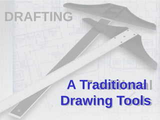
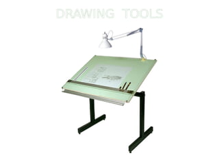
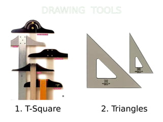
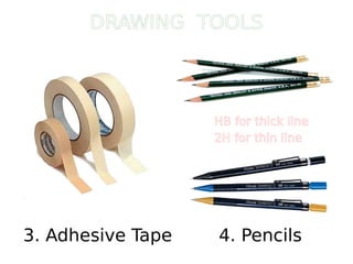
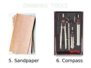
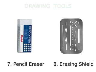
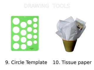
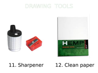
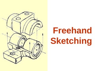
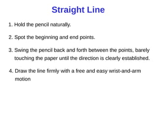
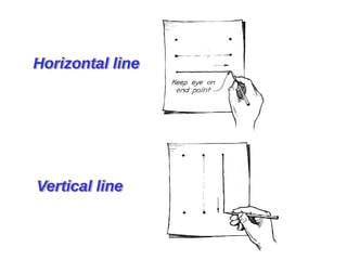
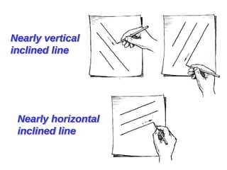
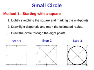
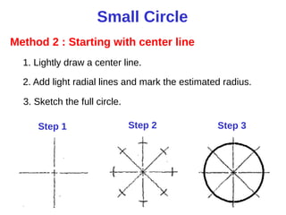
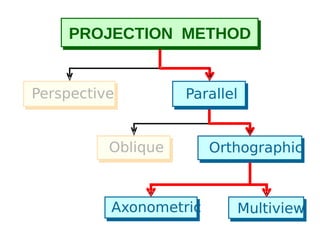
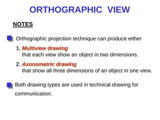
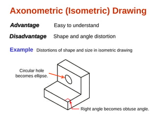
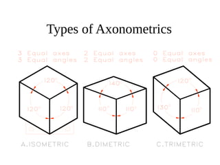
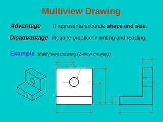
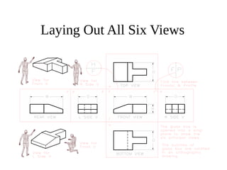
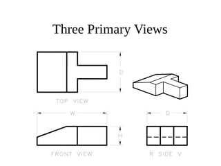
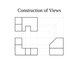
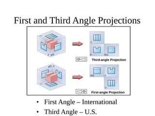
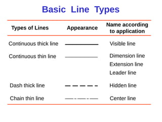
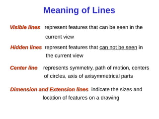
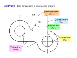

The document provides information on traditional engineering drawing tools and techniques. It discusses various drawing tools used for drafting like T-squares, triangles, pencils, erasers. It also explains different drawing techniques like freehand sketching, using instruments to draw lines, circles and curves. The document further describes orthographic projections, types of projections like multiview, axonometric drawings. It provides examples of different line types used in drawings along with standard practices and international standards for engineering drawings.