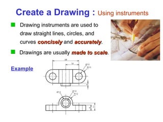
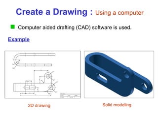
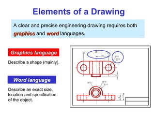
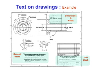
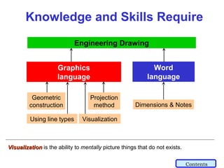
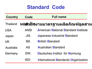
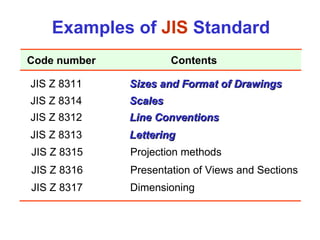
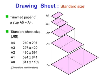
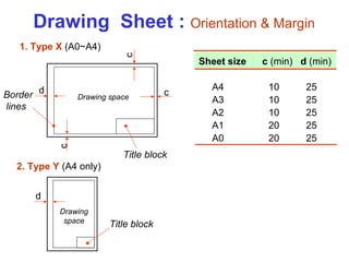
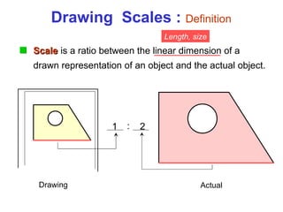
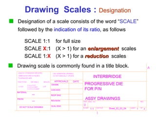
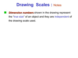
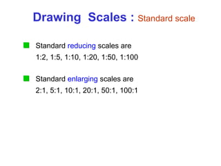
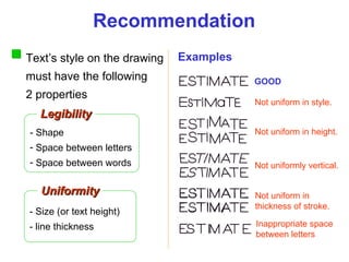
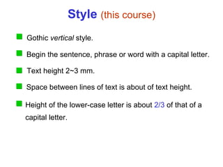
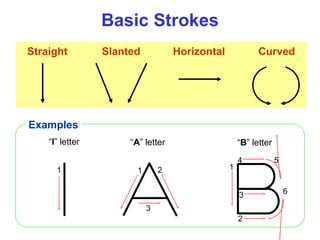
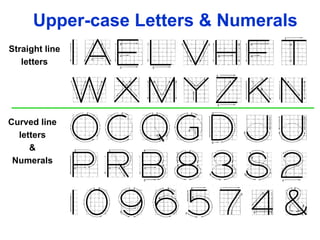
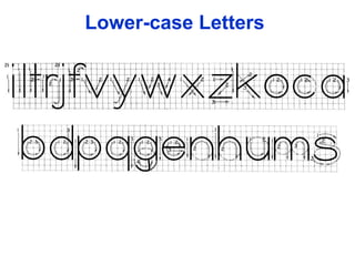
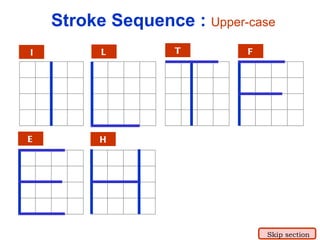
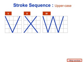
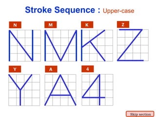
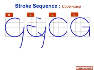
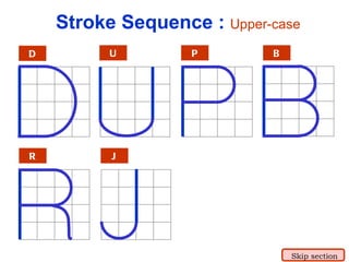
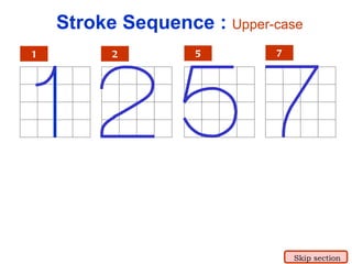
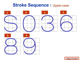
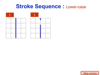
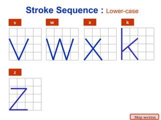
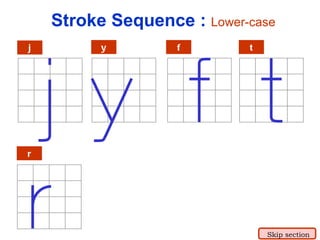
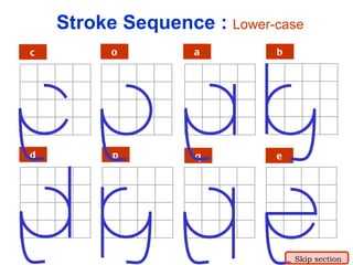
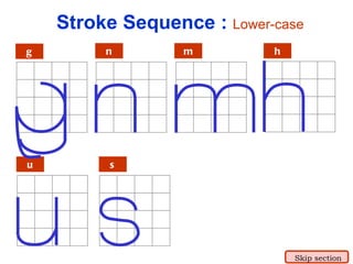
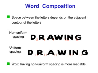
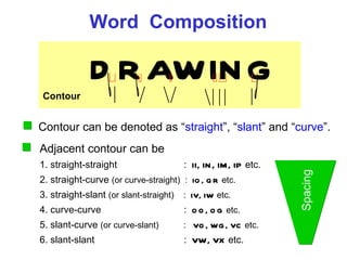
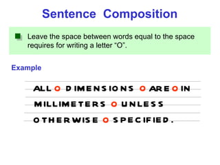
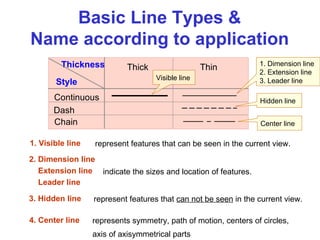
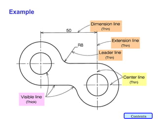
Chapter 1 Introduction
Contents Drawing standards Engineering drawing Drawing sheet Scale Lettering Line types
Engineering Drawing The words of the language, as they are written or spoken, do not seem to play any role in my mechanism of thought. The psychical entities which seem to serve as elements in thought are certain signs and more or less clear images which can be “voluntarily” reproduced and combined--this combinatory play seems to be the essential feature in productive thought before there is any connection with logical construction in words or other kinds of signs which are communicated to others   --Albert Einstein Contents
1. Try to write a  description  of this object. 2. Test your written description by having someone attempt   to  make a sketch  or  visualize   from your description. Effectiveness of Graphic Language The word language is  inadequate  for describing the  size ,  shape   and  features   completely as well as concisely. You can easily understand that …
Graphic Language in Engineering Drawing “ Engineering drawing”  or  “blueprint”  uses  l ines   to represent the  features  of an object. Features   of an object are  surface  (include  plane ) and edge . Surface Edge
A drawing can be created in 3 ways Ways to Create an Engineering Drawing Freehand sketch Using typical drawing instruments Using a computer
Example Create a Drawing :  Freehand sketch Pictorial sketch Orthographic sketch The lines are drawn using only pencil and erasers on a blank or grid paper.
Example Create a Drawing :  Using instruments Drawing instruments are used to draw straight lines, circles, and curves  concisely  and  accurately .  Drawings are usually  made to scale .
Example Create a Drawing :  Using a computer 2D drawing Solid modeling Computer aided drafting (CAD) software is used.
Elements of a Drawing A clear and precise engineering drawing requires both  graphics  and  word  languages. Graphics language Describe a shape (mainly). Word language Describe an exact size, location and specification of the object.
Text on drawings :  Example General notes Title block Dimensions & Notes
Knowledge and Skills Require Graphics language Word language Visualization  is the ability to  mentally  picture things that do not exists. Engineering Drawing Dimensions & Notes Visualization Using line types Geometric construction Projection method Contents
Drawing Standard Drawing sheet Scale Lettering Line types Contents
Definition and Necessity Drawing standards are  set of rules  that govern how technical drawings are represented. Drawing standards are used so that drawings  convey the same meaning   to everyone who reads them.
Standard  Code ISO I nternational  S tandards  O rganization ANSI A merican  N ational  S tandard  I nstitute USA JIS J apanese  I ndustrial  S tandard Japan BS B ritish  S tandard UK AS A ustralian  S tandard Australia D eutsches  I nstitut  f ü r   N ormung DIN Germany Country Code Full name มอก . / TIS สำนักงานมาตรฐานผลิตภัณฑ์อุตสาหกรรม Thailand
JIS Z 8311    Sizes and Format of Drawings JIS Z 8312    Line Conventions JIS Z 8313    Lettering JIS Z 8314    Scales JIS Z 8315   Projection methods JIS Z 8316   Presentation of Views and Sections JIS Z 8317   Dimensioning Examples of  JIS  Standard Code number Contents
Drawing Standard Drawing Sheet Drawing standard Contents
Drawing  Sheet :  Standard size Trimmed paper of a size A0 ~ A4. Standard sheet size   ( JIS ) A4   210 x 297 A3   297 x 420 A2   420 x 594 A1   594 x 841 A0   841 x 1189 A4 A3 A2 A1 A0 (Dimensions in millimeters)
Drawing space Drawing space Title block Border lines 1. Type X  (A0~A4) 2. Type Y  (A4 only) Title block Drawing  Sheet :  Orientation & Margin d d c c c Sheet size  c  (min)   d  (min) A4  10  25 A3  10  25  A2  10  25 A1  20  25 A0  20  25
Drawing Standard Drawing Scale Drawing standard Contents
Drawing  Scales :  Definition Drawing Actual Length, size 1 2 : Scale  is a ratio between the linear dimension of a drawn representation of an object and the actual object.
SCALE 1:1 for full size SCALE  X :1 (X > 1) for an  enlargement   scales SCALE 1: X (X > 1)  for a  reduction   scales Drawing  Scales :  Designation Designation of a scale consists of the word “ SCALE ”  followed by the  indication of its ratio , as follows Drawing scale is commonly found in a title block.
Drawing  Scales :  Notes Dimension numbers  shown in the drawing represent the “ true size ” of an object and they are  independent  of the drawing scale used.
Drawing  Scales :  Standard scale Standard  reducing  scales are 1:2, 1:5, 1:10, 1:20, 1:50, 1:100 Standard  enlarging  scales are 2:1, 5:1, 10:1, 20:1, 50:1, 100:1
Drawing Standard Lettering Drawing standard Contents
- Size (or text height) - line thickness - Shape Space between letters Space between words Recommendation Legibility Uniformity Examples GOOD Not uniform in style. Not uniform in height. Not uniformly vertical. Not uniform in thickness of stroke. Inappropriate space between letters Text’s style on the drawing must have the following 2 properties
Style  (this course) Gothic  vertical  style. Begin the sentence, phrase or word with a capital letter. Text height 2~3 mm.  Space between lines of text is about of text height. Height of the lower-case letter is about  2/3  of that of a capital letter.
Basic Strokes Straight Slanted Curved Horizontal 1 1 2 3 “ I ” letter “ A ” letter 1 2 3 4 5 6 “ B ” letter Examples
Suggested Strokes Sequence Straight line letters Curved line letters & Numerals Upper-case Letters & Numerals
Lower-case Letters
I L T F E H Stroke Sequence :  Upper-case Skip section
V X W Stroke Sequence :  Upper-case Skip section
N M K Z Y A 4 Stroke Sequence :  Upper-case Skip section
O Q C G Stroke Sequence :  Upper-case Skip section
D U P B R J Stroke Sequence :  Upper-case Skip section
5 7 Stroke Sequence :  Upper-case 1 2 Skip section
6 8 9 0 S 3 Stroke Sequence :  Upper-case Skip section
l i Stroke Sequence :  Lower-case Skip section
v w x k z Stroke Sequence :  Lower-case Skip section
j y f r t Stroke Sequence :  Lower-case Skip section
c o a b d p q e Stroke Sequence :  Lower-case Skip section
g n m h u s Stroke Sequence :  Lower-case Skip section
DRAWING Word  Composition Non-uniform spacing Uniform spacing D R A W I N G Space between the letters depends on the adjacent contour of the letters. Word having non-uniform spacing is more readable.
Word  Composition Contour DRAWING Adjacent contour can be 1. straight-straight   :  II, IN, IM, IP  etc. 2. straight-curve  (or curve-straight)  :  IO, QR  etc. 3. straight-slant  (or slant-straight)   :  IV, IW  etc. 4. curve-curve   :  OO, OG  etc. 5. slant-curve  (or curve-slant)   :  VO, WG, VC  etc. 6. slant-slant   :  VW, VX  etc. Spacing Contour can be denoted as “ straight ”, “ slant ” and “ curve ”.
Leave the space between words equal to the space requires for writing a letter “O”.  Example Sentence  Composition ALL DIMENSIONS ARE IN MILLIMETERS O O O O UNLESS OTHERWISE SPECIFIED. O
Drawing Standard Line Types Drawing standard Contents
Basic Line Types & Name according to application Continuous Dash Chain Style Thickness Thick Thin 1. Dimension line 2. Extension line 3. Leader line Center line Hidden line Visible line represent features that can be seen in the current view. represent features that  can not be seen  in the current view. represents symmetry, path of motion, centers of circles, axis of axisymmetrical parts indicate the sizes and location of features. 1. Visible line 3. Hidden line 4. Center line 2. Dimension line Extension line Leader line
Example Contents

Engineering Drawing: Chapter 01 introduction

  • 1.
  • 2.
    Contents Drawing standardsEngineering drawing Drawing sheet Scale Lettering Line types
  • 3.
    Engineering Drawing Thewords of the language, as they are written or spoken, do not seem to play any role in my mechanism of thought. The psychical entities which seem to serve as elements in thought are certain signs and more or less clear images which can be “voluntarily” reproduced and combined--this combinatory play seems to be the essential feature in productive thought before there is any connection with logical construction in words or other kinds of signs which are communicated to others --Albert Einstein Contents
  • 4.
    1. Try towrite a description of this object. 2. Test your written description by having someone attempt to make a sketch or visualize from your description. Effectiveness of Graphic Language The word language is inadequate for describing the size , shape and features completely as well as concisely. You can easily understand that …
  • 5.
    Graphic Language inEngineering Drawing “ Engineering drawing” or “blueprint” uses l ines to represent the features of an object. Features of an object are surface (include plane ) and edge . Surface Edge
  • 6.
    A drawing canbe created in 3 ways Ways to Create an Engineering Drawing Freehand sketch Using typical drawing instruments Using a computer
  • 7.
    Example Create aDrawing : Freehand sketch Pictorial sketch Orthographic sketch The lines are drawn using only pencil and erasers on a blank or grid paper.
  • 8.
    Example Create aDrawing : Using instruments Drawing instruments are used to draw straight lines, circles, and curves concisely and accurately . Drawings are usually made to scale .
  • 9.
    Example Create aDrawing : Using a computer 2D drawing Solid modeling Computer aided drafting (CAD) software is used.
  • 10.
    Elements of aDrawing A clear and precise engineering drawing requires both graphics and word languages. Graphics language Describe a shape (mainly). Word language Describe an exact size, location and specification of the object.
  • 11.
    Text on drawings: Example General notes Title block Dimensions & Notes
  • 12.
    Knowledge and SkillsRequire Graphics language Word language Visualization is the ability to mentally picture things that do not exists. Engineering Drawing Dimensions & Notes Visualization Using line types Geometric construction Projection method Contents
  • 13.
    Drawing Standard Drawingsheet Scale Lettering Line types Contents
  • 14.
    Definition and NecessityDrawing standards are set of rules that govern how technical drawings are represented. Drawing standards are used so that drawings convey the same meaning to everyone who reads them.
  • 15.
    Standard CodeISO I nternational S tandards O rganization ANSI A merican N ational S tandard I nstitute USA JIS J apanese I ndustrial S tandard Japan BS B ritish S tandard UK AS A ustralian S tandard Australia D eutsches I nstitut f ü r N ormung DIN Germany Country Code Full name มอก . / TIS สำนักงานมาตรฐานผลิตภัณฑ์อุตสาหกรรม Thailand
  • 16.
    JIS Z 8311 Sizes and Format of Drawings JIS Z 8312 Line Conventions JIS Z 8313 Lettering JIS Z 8314 Scales JIS Z 8315 Projection methods JIS Z 8316 Presentation of Views and Sections JIS Z 8317 Dimensioning Examples of JIS Standard Code number Contents
  • 17.
    Drawing Standard DrawingSheet Drawing standard Contents
  • 18.
    Drawing Sheet: Standard size Trimmed paper of a size A0 ~ A4. Standard sheet size ( JIS ) A4 210 x 297 A3 297 x 420 A2 420 x 594 A1 594 x 841 A0 841 x 1189 A4 A3 A2 A1 A0 (Dimensions in millimeters)
  • 19.
    Drawing space Drawingspace Title block Border lines 1. Type X (A0~A4) 2. Type Y (A4 only) Title block Drawing Sheet : Orientation & Margin d d c c c Sheet size c (min) d (min) A4 10 25 A3 10 25 A2 10 25 A1 20 25 A0 20 25
  • 20.
    Drawing Standard DrawingScale Drawing standard Contents
  • 21.
    Drawing Scales: Definition Drawing Actual Length, size 1 2 : Scale is a ratio between the linear dimension of a drawn representation of an object and the actual object.
  • 22.
    SCALE 1:1 forfull size SCALE X :1 (X > 1) for an enlargement scales SCALE 1: X (X > 1) for a reduction scales Drawing Scales : Designation Designation of a scale consists of the word “ SCALE ” followed by the indication of its ratio , as follows Drawing scale is commonly found in a title block.
  • 23.
    Drawing Scales: Notes Dimension numbers shown in the drawing represent the “ true size ” of an object and they are independent of the drawing scale used.
  • 24.
    Drawing Scales: Standard scale Standard reducing scales are 1:2, 1:5, 1:10, 1:20, 1:50, 1:100 Standard enlarging scales are 2:1, 5:1, 10:1, 20:1, 50:1, 100:1
  • 25.
    Drawing Standard LetteringDrawing standard Contents
  • 26.
    - Size (ortext height) - line thickness - Shape Space between letters Space between words Recommendation Legibility Uniformity Examples GOOD Not uniform in style. Not uniform in height. Not uniformly vertical. Not uniform in thickness of stroke. Inappropriate space between letters Text’s style on the drawing must have the following 2 properties
  • 27.
    Style (thiscourse) Gothic vertical style. Begin the sentence, phrase or word with a capital letter. Text height 2~3 mm. Space between lines of text is about of text height. Height of the lower-case letter is about 2/3 of that of a capital letter.
  • 28.
    Basic Strokes StraightSlanted Curved Horizontal 1 1 2 3 “ I ” letter “ A ” letter 1 2 3 4 5 6 “ B ” letter Examples
  • 29.
    Suggested Strokes SequenceStraight line letters Curved line letters & Numerals Upper-case Letters & Numerals
  • 30.
  • 31.
    I L TF E H Stroke Sequence : Upper-case Skip section
  • 32.
    V X WStroke Sequence : Upper-case Skip section
  • 33.
    N M KZ Y A 4 Stroke Sequence : Upper-case Skip section
  • 34.
    O Q CG Stroke Sequence : Upper-case Skip section
  • 35.
    D U PB R J Stroke Sequence : Upper-case Skip section
  • 36.
    5 7 StrokeSequence : Upper-case 1 2 Skip section
  • 37.
    6 8 90 S 3 Stroke Sequence : Upper-case Skip section
  • 38.
    l i StrokeSequence : Lower-case Skip section
  • 39.
    v w xk z Stroke Sequence : Lower-case Skip section
  • 40.
    j y fr t Stroke Sequence : Lower-case Skip section
  • 41.
    c o ab d p q e Stroke Sequence : Lower-case Skip section
  • 42.
    g n mh u s Stroke Sequence : Lower-case Skip section
  • 43.
    DRAWING Word Composition Non-uniform spacing Uniform spacing D R A W I N G Space between the letters depends on the adjacent contour of the letters. Word having non-uniform spacing is more readable.
  • 44.
    Word CompositionContour DRAWING Adjacent contour can be 1. straight-straight : II, IN, IM, IP etc. 2. straight-curve (or curve-straight) : IO, QR etc. 3. straight-slant (or slant-straight) : IV, IW etc. 4. curve-curve : OO, OG etc. 5. slant-curve (or curve-slant) : VO, WG, VC etc. 6. slant-slant : VW, VX etc. Spacing Contour can be denoted as “ straight ”, “ slant ” and “ curve ”.
  • 45.
    Leave the spacebetween words equal to the space requires for writing a letter “O”. Example Sentence Composition ALL DIMENSIONS ARE IN MILLIMETERS O O O O UNLESS OTHERWISE SPECIFIED. O
  • 46.
    Drawing Standard LineTypes Drawing standard Contents
  • 47.
    Basic Line Types& Name according to application Continuous Dash Chain Style Thickness Thick Thin 1. Dimension line 2. Extension line 3. Leader line Center line Hidden line Visible line represent features that can be seen in the current view. represent features that can not be seen in the current view. represents symmetry, path of motion, centers of circles, axis of axisymmetrical parts indicate the sizes and location of features. 1. Visible line 3. Hidden line 4. Center line 2. Dimension line Extension line Leader line
  • 48.