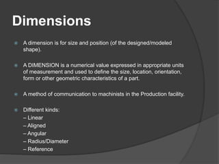
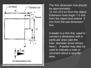
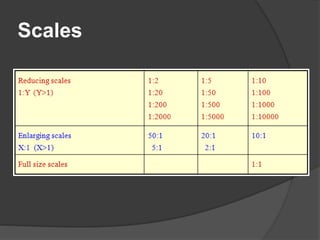
2110013
Dimensions
 A dimension is for size and position (of the designed/modeled
shape).
 A DIMENSION is a numerical value expressed in appropriate units
of measurement and used to define the size, location, orientation,
form or other geometric characteristics of a part.
 A method of communication to machinists in the Production facility.
 Different kinds:
– Linear
– Aligned
– Angular
– Radius/Diameter
– Reference
Dimensions
 The purpose of dimensioning is to provide a clear and complete
description of an object.
 A complete set of dimensions will permit only one interpretation
needed to construct the part.
 Dimensioning should follow these guidelines.
Accuracy: correct values must be given.
Clearness: dimensions must be placed in appropriate positions.
Completeness: nothing must be left out, and nothing duplicated.
Readability: the appropriate line quality must be used for legibility.
The first dimension line should
be approximately
12 mm (0.6 in) from the object.
Extension lines begin 1.5 mm
from the object and extend 3
mm from the last dimension
line.
A leader is a thin line, used to
connect a dimension with a
particular area (see the
hole diameter arrow shown
here.) A leader may also be
used to indicate a note or
comment about a specific
area.
When there is limited
space, a heavy black
dot may be substituted
for the arrows, again
clarity is the rule - it
should be a clear point
into which the dimension
lines ends.
Also in this drawing,
shown here, two holes
on the main surface of
the flat panel are
identical, allowing the
"2x" notation to be used
and the dimension to
point to only one of the
circles. This is more
preferable than cluttering
the space with duplicate
information.
Types of Dimensioning
 To show dimensions of all parts of drawing
is mandatory for engineer.
 All lines in drawing would have length, width or
radius to indicate.
 The use of proper dimensioning method will tends to
full marks for correct drawing.
 Now let us discuss methods of dimensioning in brief.
 There are two Methods of Dimensions. (1) Uni-
directional System (2) Aligned System.
1) Uni-directional System
In Unidirectional
Method
of Dimensioning
the dimension
line should be cut
at center and
dimensions
should be placed
in the middle of
dimension lines
as shown into the
figure.
2) Aligned System
In Aligned Method
of Dimensioning the
dimension line
should be
continuous and
dimensions should
be placed in the
middle of dimension
lines as shown into
the figure.
Line styles and types
 A variety of line styles graphically represent
physical objects. Types of lines include the
following:
visible – are continuous lines used to depict
edges directly visible from a particular angle.
hidden – are short-dashed lines that may be
used to represent edges that are not directly
visible.
Line styles and types
center – are alternately long- and short-dashed lines
that may be used to represent the axes of circular
features.
cutting plane – are thin, medium-dashed lines, or
thick alternately long- and double short-dashed that
may be used to define sections for section views.
section – are thin lines in a pattern (pattern
determined by the material being "cut" or
"sectioned") used to indicate surfaces in section
views resulting from "cutting." Section lines are
commonly referred to as "cross-hatching."
Line styles and types
Scales
 A scale is defined as the ratio of the linear
dimensions of the object as represented in a
drawing to the actual dimensions of the same.
 There is a wide variation in sizes for engineering
objects. Some are very large (eg. Aero planes,
rockets, etc) Some are vey small ( wrist watch,
MEMs components)
There is a need to reduce or enlarge while drawing
the objects on paper. Some objects can be drawn to
their actual size. The proportion by which the
drawing of aan object is enlarged or reduced is
called the scale of the drawing.
Scales
Scales
 Types of Scale :-
Engineers Scale : The relation between
the dimension on the drawing and the
actual dimension of the object is mentioned
numerically (like 10 mm = 15 m).
Graphical Scale: Scale is drawn on the
drawing itself. This takes care of the
shrinkage of the engineer’s scale when the
drawing becomes old.
Scales
 Types of Graphical Scale :-
Plain Scale
Diagonal Scale
Vernier Scale
Comparative scale
Scale of chords
Scales
Plain Scale Diagonal Scale
Multiple views and
projections
 The orthographic projection shows the
object as it looks from the front, right,
left, top, bottom, or back, and are
typically positioned relative to each other
according to the rules of either first-
angle or third-angle projection. The
origin and vector direction of the
projectors (also called projection lines)
differs, as explained below.
Multiple views and
projections
 In first-angle projection, the projectors originate as if
radiated from a viewer's eyeballs and shoot through the 3D
object to project a 2D image onto the plane behind it. The
3D object is projected into 2D "paper" space as if you were
looking at a radiograph of the object: the top view is under the
front view, the right view is at the left of the front view.
 In third-angle projection, the projectors originate as if
radiated from the 3D object itself and shoot away from the
3D object to project a 2D image onto the plane in front
of it. The views of the 3D object are like the panels of a box that
envelopes the object, and the panels pivot as they open up flat
into the plane of the drawing. Thus the left view is placed on the
left and the top view on the top; and the features closest to the
front of the 3D object will appear closest to the front view in the
drawing.
Prepared by …. Class FX
students
 Akash Ambaliya_140030119003
 Vivek Aghara_140030119001
Thank You…

Dimensioning, scales, lines and multiple projections

  • 1.
  • 3.
    Dimensions  A dimensionis for size and position (of the designed/modeled shape).  A DIMENSION is a numerical value expressed in appropriate units of measurement and used to define the size, location, orientation, form or other geometric characteristics of a part.  A method of communication to machinists in the Production facility.  Different kinds: – Linear – Aligned – Angular – Radius/Diameter – Reference
  • 4.
    Dimensions  The purposeof dimensioning is to provide a clear and complete description of an object.  A complete set of dimensions will permit only one interpretation needed to construct the part.  Dimensioning should follow these guidelines. Accuracy: correct values must be given. Clearness: dimensions must be placed in appropriate positions. Completeness: nothing must be left out, and nothing duplicated. Readability: the appropriate line quality must be used for legibility.
  • 5.
    The first dimensionline should be approximately 12 mm (0.6 in) from the object. Extension lines begin 1.5 mm from the object and extend 3 mm from the last dimension line. A leader is a thin line, used to connect a dimension with a particular area (see the hole diameter arrow shown here.) A leader may also be used to indicate a note or comment about a specific area.
  • 6.
    When there islimited space, a heavy black dot may be substituted for the arrows, again clarity is the rule - it should be a clear point into which the dimension lines ends. Also in this drawing, shown here, two holes on the main surface of the flat panel are identical, allowing the "2x" notation to be used and the dimension to point to only one of the circles. This is more preferable than cluttering the space with duplicate information.
  • 7.
    Types of Dimensioning To show dimensions of all parts of drawing is mandatory for engineer.  All lines in drawing would have length, width or radius to indicate.  The use of proper dimensioning method will tends to full marks for correct drawing.  Now let us discuss methods of dimensioning in brief.  There are two Methods of Dimensions. (1) Uni- directional System (2) Aligned System.
  • 8.
    1) Uni-directional System InUnidirectional Method of Dimensioning the dimension line should be cut at center and dimensions should be placed in the middle of dimension lines as shown into the figure.
  • 9.
    2) Aligned System InAligned Method of Dimensioning the dimension line should be continuous and dimensions should be placed in the middle of dimension lines as shown into the figure.
  • 10.
    Line styles andtypes  A variety of line styles graphically represent physical objects. Types of lines include the following: visible – are continuous lines used to depict edges directly visible from a particular angle. hidden – are short-dashed lines that may be used to represent edges that are not directly visible.
  • 11.
    Line styles andtypes center – are alternately long- and short-dashed lines that may be used to represent the axes of circular features. cutting plane – are thin, medium-dashed lines, or thick alternately long- and double short-dashed that may be used to define sections for section views. section – are thin lines in a pattern (pattern determined by the material being "cut" or "sectioned") used to indicate surfaces in section views resulting from "cutting." Section lines are commonly referred to as "cross-hatching."
  • 12.
  • 13.
    Scales  A scaleis defined as the ratio of the linear dimensions of the object as represented in a drawing to the actual dimensions of the same.  There is a wide variation in sizes for engineering objects. Some are very large (eg. Aero planes, rockets, etc) Some are vey small ( wrist watch, MEMs components) There is a need to reduce or enlarge while drawing the objects on paper. Some objects can be drawn to their actual size. The proportion by which the drawing of aan object is enlarged or reduced is called the scale of the drawing.
  • 14.
  • 15.
    Scales  Types ofScale :- Engineers Scale : The relation between the dimension on the drawing and the actual dimension of the object is mentioned numerically (like 10 mm = 15 m). Graphical Scale: Scale is drawn on the drawing itself. This takes care of the shrinkage of the engineer’s scale when the drawing becomes old.
  • 16.
    Scales  Types ofGraphical Scale :- Plain Scale Diagonal Scale Vernier Scale Comparative scale Scale of chords
  • 17.
  • 18.
    Multiple views and projections The orthographic projection shows the object as it looks from the front, right, left, top, bottom, or back, and are typically positioned relative to each other according to the rules of either first- angle or third-angle projection. The origin and vector direction of the projectors (also called projection lines) differs, as explained below.
  • 19.
    Multiple views and projections In first-angle projection, the projectors originate as if radiated from a viewer's eyeballs and shoot through the 3D object to project a 2D image onto the plane behind it. The 3D object is projected into 2D "paper" space as if you were looking at a radiograph of the object: the top view is under the front view, the right view is at the left of the front view.  In third-angle projection, the projectors originate as if radiated from the 3D object itself and shoot away from the 3D object to project a 2D image onto the plane in front of it. The views of the 3D object are like the panels of a box that envelopes the object, and the panels pivot as they open up flat into the plane of the drawing. Thus the left view is placed on the left and the top view on the top; and the features closest to the front of the 3D object will appear closest to the front view in the drawing.
  • 20.
    Prepared by ….Class FX students  Akash Ambaliya_140030119003  Vivek Aghara_140030119001
  • 21.