Chapter 1
Introduction to
Engineering Drawing
TOPICS
Drawing standards
Projection methods
Orthographic projection
Graphics language
Engineering drawing
Traditional Drawing Tools
GRAPHICS
LANGUAGE
1. Try to write a description of
this object.
2. Test your written description
by having someone attempt
to make a sketch from your
description.
Effectiveness of Graphics Language
The word languages are inadequate for describing the
size
size, shape
shape and features
features completely as well as
concisely.
You can easily understand that …
Graphic language in “engineering application” use
l
lines
ines to represent the surfaces
surfaces, edges
edges and contours
contours
of objects.
A drawing can be done using freehand
freehand, instruments
instruments
or computer
computer methods.
Composition of Graphic Language
The language is known as “drawing
drawing” or “drafting
drafting” .
Freehand drawing
Freehand drawing
The lines are sketched without using instruments other
than pencils and erasers.
Example
Instrument drawing
Instrument drawing
Instruments are used to draw straight lines, circles, and
curves concisely and accurately. Thus, the drawings are
usually made to scale.
Example
Computer drawing
Computer drawing
The drawings are usually made by commercial software
such as AutoCAD, solid works etc.
Example
Engineering
Drawing
Elements of Engineering Drawing
Engineering drawing are made up of graphics language
graphics language
and word language
word language.
Graphics
language
Describe a shape
(mainly).
Word
language
Describe size, location and
specification of the object.
Basic Knowledge for Drafting
Graphics
language
Word
language
Line
types
Geometric
construction Lettering
Projection
method
PROJECTION
METHOD
PROJECTION METHOD
Perspective
Oblique Orthographic
Axonometric Multiview
Parallel
PROJECTION THEORY
The projection theory is based on two variables:
1) Line of sight
2) Plane of projection (image plane or picture plane)
The projection theory is used to graphically represent
3-D objects on 2-D media (paper, computer screen).
Line of sight
Line of sight is an imaginary ray of light between an
observer’s eye and an object.
Line of sight
Parallel projection
Parallel projection
Line of sight
Perspective projection
There are 2 types of LOS : parallel converge
and
Plane of projection
Plane of projection is an imaginary flat plane which
the image is created.
The image is produced by connecting the points where
the LOS pierce the projection plane.
Parallel projection
Parallel projection Perspective projection
Perspective projection
Plane of projection Plane of projection
Disadvantage of
Perspective Projection
Perspective projection is not
not
used by engineer for manu-
facturing of parts, because
1) It is difficult to create.
2) It does not reveal exact
shape and size.
Width is distorted
Orthographic
Projection
5
Orthographic projection
Orthographic projection is a parallel projection technique
in which the parallel lines of sight are perpendicular to the
projection plane
MEANING
Object views from top
Projection plane
1
2
3
4
5
1 2 3 4
ORTHOGRAPHIC VIEW
Orthographic view
Orthographic view depends on relative position of the object
to the line of sight.
Two dimensions of an
object is shown.
Three dimensions of an object is shown.
Rotate
Tilt
More than one view is needed
to represent the object.
Multiview drawing
Multiview drawing
Axonometric drawing
Axonometric drawing
Orthographic projection technique can produce either
1.
1. Multiview drawing
Multiview drawing
that each view show an object in two dimensions.
2.
2. Axonometric drawing
Axonometric drawing
that show all three dimensions of an object in one view.
Both drawing types are used in technical drawing for
communication.
NOTES
ORTHOGRAPHIC VIEW
Axonometric (Isometric) Drawing
Easy to understand
Right angle becomes obtuse angle.
Circular hole
becomes ellipse.
Distortions of shape and size in isometric drawing
Advantage
Advantage
Disadvantage
Disadvantage Shape and angle distortion
Example
Multiview Drawing
It represents accurate shape and size.
Advantage
Advantage
Disadvantage
Disadvantage Require practice in writing and reading.
Multiviews drawing (2-view drawing)
Example
Drawing Standard
Introduction
Standards
Standards are set of rules that govern how technical
drawings are represented.
Drawing standards are used so that drawings convey
the same meaning to everyone who reads them.
ISO International Standards Organization
Standard Code
ANSI American National Standard Institute
USA
JIS Japanese Industrial Standard
Japan
BS British Standard
UK
AS Australian Standard
Australia
Deutsches Institut für Normung
DIN
Germany
Country Code Full name
มอก.
สำนักงานมาตรฐานผลิตภัณฑ์อุตสาหกร
Thailand
Partial List of Drawing Standards
JIS Z 8311 Sizes and Format of Drawings
Sizes and Format of Drawings
JIS Z 8312 Line Conventions
Line Conventions
JIS Z 8313 Lettering
Lettering
JIS Z 8314 Scales
Scales
JIS Z 8315 Projection methods
JIS Z 8316 Presentation of Views and Sections
JIS Z 8317 Dimensioning
Code number Contents
Drawing Sheet
Trimmed paper of
a size A0 ~ A4.
Standard sheet size
(JIS)
A4 210 x 297
A3 297 x 420
A2 420 x 594
A1 594 x 841
A0 841 x 1189
A4
A3
A2
A1
A0
(Dimensions in millimeters)
Drawing space Drawing
space
Title block
d
d
c
c
c
Border
lines
1. Type X (A0~A4) 2. Type Y (A4 only)
Orientation of drawing sheet
Title block
Sheet size c (min) d (min)
A4 10 25
A3 10 25
A2 10 25
A1 20 25
A0 20 25
DRN. BY DEPA.
ID NO DATE
CHD. BY SEC. DR. NO
TITLE Title or Full Name of the Drawing
Angle of Projection
SCALE 1:1 ALL DIEMENSION ARE IN mm
Drawing Scales
Scale
Scale is the ratio of the linear dimension of an element
of an object shown in the drawing to the real linear
dimension of the same element of the object.
Size in drawing Actual size
Length, size
:
Drawing Scales
Designation of a scale consists of the word “SCALE”
followed by the indication of its ratio, as follow
SCALE 1:1 for full size
SCALE X:1 for enlargement
enlargement scales (X > 1)
SCALE 1:X for reduction
reduction scales (X > 1)
Dimension numbers shown in the drawing are correspond
to “true size” of the object and they are independent of
the scale used in creating that drawing.
Basic Line Types
Types of Lines Appearance
Name according
to application
Continuous thick line Visible line
Continuous thin line Dimension line
Extension line
Leader line
Dash thick line Hidden line
Chain thin line Center line
NOTE : We will learn other types of line in later chapters.
Visible lines
Visible lines represent features that can be seen in the
current view
Meaning of Lines
Hidden lines
Hidden lines represent features that can not be seen in
the current view
Center line
Center line represents symmetry, path of motion, centers
of circles, axis of axisymmetrical parts
Dimension and Extension lines
Dimension and Extension lines indicate the sizes and
location of features on a drawing
Example : Line conventions in engineering drawing
Traditional
Drawing Tools
DRAWING TOOLS
1. T-Square 2. Triangles
DRAWING TOOLS
3. Adhesive Tape 4. Pencils
2H or HB for thick line
4H for thin line
DRAWING TOOLS
5. Sandpaper 6. Compass
DRAWING TOOLS
7. Pencil Eraser 8. Erasing Shield
DRAWING TOOLS
9. Circle Template 10. Tissue paper
DRAWING TOOLS
11. Sharpener 12. Clean paper
DRAWING TOOLS

Chapter 01 Introduction.ppt for engineering drawing

  • 1.
  • 2.
    TOPICS Drawing standards Projection methods Orthographicprojection Graphics language Engineering drawing Traditional Drawing Tools
  • 3.
  • 4.
    1. Try towrite a description of this object. 2. Test your written description by having someone attempt to make a sketch from your description. Effectiveness of Graphics Language The word languages are inadequate for describing the size size, shape shape and features features completely as well as concisely. You can easily understand that …
  • 5.
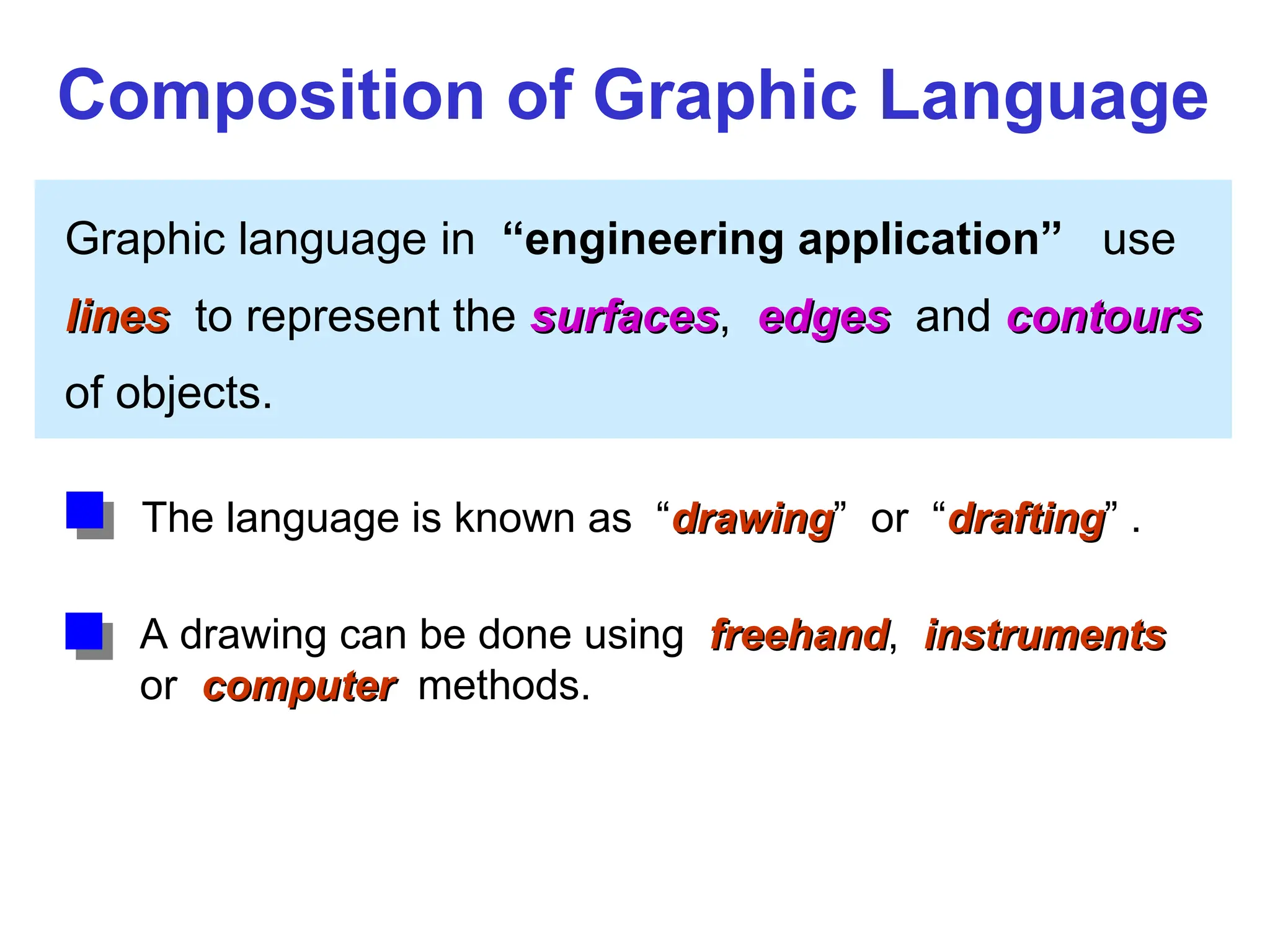
    Graphic language in“engineering application” use l lines ines to represent the surfaces surfaces, edges edges and contours contours of objects. A drawing can be done using freehand freehand, instruments instruments or computer computer methods. Composition of Graphic Language The language is known as “drawing drawing” or “drafting drafting” .
  • 6.
    Freehand drawing Freehand drawing Thelines are sketched without using instruments other than pencils and erasers. Example
  • 7.
    Instrument drawing Instrument drawing Instrumentsare used to draw straight lines, circles, and curves concisely and accurately. Thus, the drawings are usually made to scale. Example
  • 8.
    Computer drawing Computer drawing Thedrawings are usually made by commercial software such as AutoCAD, solid works etc. Example
  • 9.
  • 10.
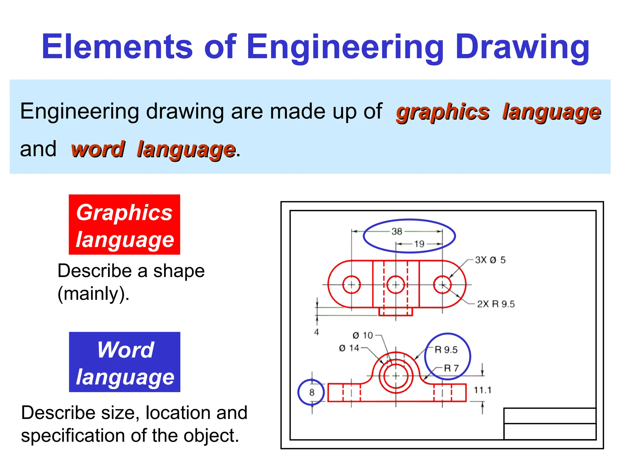
    Elements of EngineeringDrawing Engineering drawing are made up of graphics language graphics language and word language word language. Graphics language Describe a shape (mainly). Word language Describe size, location and specification of the object.
  • 11.
    Basic Knowledge forDrafting Graphics language Word language Line types Geometric construction Lettering Projection method
  • 12.
  • 13.
  • 14.
    PROJECTION THEORY The projectiontheory is based on two variables: 1) Line of sight 2) Plane of projection (image plane or picture plane) The projection theory is used to graphically represent 3-D objects on 2-D media (paper, computer screen).
  • 15.
    Line of sight Lineof sight is an imaginary ray of light between an observer’s eye and an object. Line of sight Parallel projection Parallel projection Line of sight Perspective projection Perspective projection There are 2 types of LOS : parallel converge and
  • 16.
    Plane of projection Planeof projection is an imaginary flat plane which the image is created. The image is produced by connecting the points where the LOS pierce the projection plane. Parallel projection Parallel projection Perspective projection Perspective projection Plane of projection Plane of projection
  • 17.
    Disadvantage of Perspective Projection Perspectiveprojection is not not used by engineer for manu- facturing of parts, because 1) It is difficult to create. 2) It does not reveal exact shape and size. Width is distorted
  • 18.
  • 19.
    5 Orthographic projection Orthographic projectionis a parallel projection technique in which the parallel lines of sight are perpendicular to the projection plane MEANING Object views from top Projection plane 1 2 3 4 5 1 2 3 4
  • 20.
    ORTHOGRAPHIC VIEW Orthographic view Orthographicview depends on relative position of the object to the line of sight. Two dimensions of an object is shown. Three dimensions of an object is shown. Rotate Tilt More than one view is needed to represent the object. Multiview drawing Multiview drawing Axonometric drawing Axonometric drawing
  • 21.
    Orthographic projection techniquecan produce either 1. 1. Multiview drawing Multiview drawing that each view show an object in two dimensions. 2. 2. Axonometric drawing Axonometric drawing that show all three dimensions of an object in one view. Both drawing types are used in technical drawing for communication. NOTES ORTHOGRAPHIC VIEW
  • 22.
    Axonometric (Isometric) Drawing Easyto understand Right angle becomes obtuse angle. Circular hole becomes ellipse. Distortions of shape and size in isometric drawing Advantage Advantage Disadvantage Disadvantage Shape and angle distortion Example
  • 23.
    Multiview Drawing It representsaccurate shape and size. Advantage Advantage Disadvantage Disadvantage Require practice in writing and reading. Multiviews drawing (2-view drawing) Example
  • 24.
  • 25.
    Introduction Standards Standards are setof rules that govern how technical drawings are represented. Drawing standards are used so that drawings convey the same meaning to everyone who reads them.
  • 26.
    ISO International StandardsOrganization Standard Code ANSI American National Standard Institute USA JIS Japanese Industrial Standard Japan BS British Standard UK AS Australian Standard Australia Deutsches Institut für Normung DIN Germany Country Code Full name มอก. สำนักงานมาตรฐานผลิตภัณฑ์อุตสาหกร Thailand
  • 27.
    Partial List ofDrawing Standards JIS Z 8311 Sizes and Format of Drawings Sizes and Format of Drawings JIS Z 8312 Line Conventions Line Conventions JIS Z 8313 Lettering Lettering JIS Z 8314 Scales Scales JIS Z 8315 Projection methods JIS Z 8316 Presentation of Views and Sections JIS Z 8317 Dimensioning Code number Contents
  • 28.
    Drawing Sheet Trimmed paperof a size A0 ~ A4. Standard sheet size (JIS) A4 210 x 297 A3 297 x 420 A2 420 x 594 A1 594 x 841 A0 841 x 1189 A4 A3 A2 A1 A0 (Dimensions in millimeters)
  • 29.
    Drawing space Drawing space Titleblock d d c c c Border lines 1. Type X (A0~A4) 2. Type Y (A4 only) Orientation of drawing sheet Title block Sheet size c (min) d (min) A4 10 25 A3 10 25 A2 10 25 A1 20 25 A0 20 25
  • 30.
    DRN. BY DEPA. IDNO DATE CHD. BY SEC. DR. NO TITLE Title or Full Name of the Drawing Angle of Projection SCALE 1:1 ALL DIEMENSION ARE IN mm
  • 31.
    Drawing Scales Scale Scale isthe ratio of the linear dimension of an element of an object shown in the drawing to the real linear dimension of the same element of the object. Size in drawing Actual size Length, size :
  • 32.
    Drawing Scales Designation ofa scale consists of the word “SCALE” followed by the indication of its ratio, as follow SCALE 1:1 for full size SCALE X:1 for enlargement enlargement scales (X > 1) SCALE 1:X for reduction reduction scales (X > 1) Dimension numbers shown in the drawing are correspond to “true size” of the object and they are independent of the scale used in creating that drawing.
  • 33.
    Basic Line Types Typesof Lines Appearance Name according to application Continuous thick line Visible line Continuous thin line Dimension line Extension line Leader line Dash thick line Hidden line Chain thin line Center line NOTE : We will learn other types of line in later chapters.
  • 34.
    Visible lines Visible linesrepresent features that can be seen in the current view Meaning of Lines Hidden lines Hidden lines represent features that can not be seen in the current view Center line Center line represents symmetry, path of motion, centers of circles, axis of axisymmetrical parts Dimension and Extension lines Dimension and Extension lines indicate the sizes and location of features on a drawing
  • 35.
    Example : Lineconventions in engineering drawing
  • 36.
  • 37.
  • 38.
    1. T-Square 2.Triangles DRAWING TOOLS
  • 39.
    3. Adhesive Tape4. Pencils 2H or HB for thick line 4H for thin line DRAWING TOOLS
  • 40.
    5. Sandpaper 6.Compass DRAWING TOOLS
  • 41.
    7. Pencil Eraser8. Erasing Shield DRAWING TOOLS
  • 42.
    9. Circle Template10. Tissue paper DRAWING TOOLS
  • 43.
    11. Sharpener 12.Clean paper DRAWING TOOLS