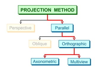
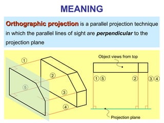
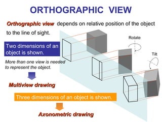
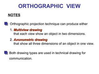
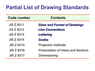
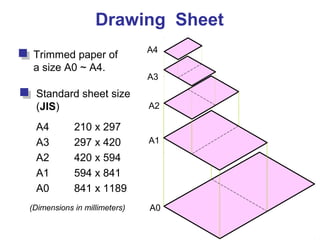
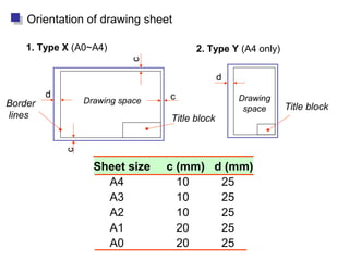
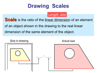
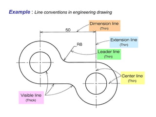
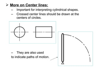
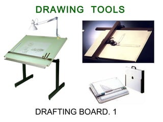
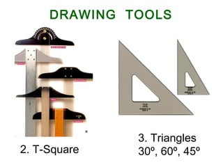
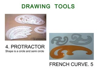
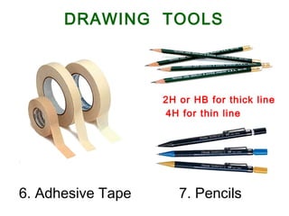
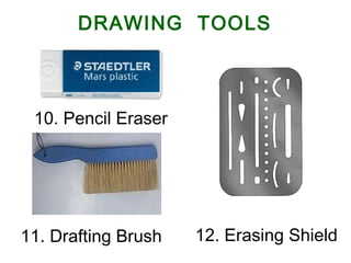
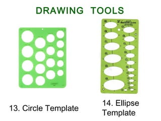
Chapter 1
Overview of an
Engineering Drawing
TOPICS
Drawing standards
Projection methods
Orthographic projection
Graphics language
Engineering drawing
TOPICS
Traditional Drawing Tools
Freehand Sketching
Lettering
GRAPHICS
LANGUAGE
1. Try to write a description of
this object.
2. Test your written description
by having someone attempt
to make a sketch from your
description.
Effectiveness of Graphics Language
The word languages are inadequate for describing the
sizesize, shapeshape and featuresfeatures completely as well as
concisely.
You can easily understand that …
A Graphic is Worth more
than a Thousand Words
Graphic language in “engineering application” use
llinesines to represent the surfacessurfaces, edgesedges and contourscontours
of objects.
A drawing can be done using freehandfreehand, instrumentsinstruments
or computercomputer methods.
Composition of Graphic Language
The language is known as “drawingdrawing” or “draftingdrafting” .
Freehand drawingFreehand drawing
The lines are sketched without using instruments other
than pencils and erasers.
Example
Instrument drawingInstrument drawing
Instruments are used to draw straight lines, circles, and
curves concisely and accurately. Thus, the drawings are
usually made to scale.
Example
Computer drawingComputer drawing
The drawings are usually made by commercial software
such as AutoCAD, solid works etc.
Example
Popular CAD programs include AutoCAD, Inventor, SolidWorks,
and ProE.
CAD Software
Applications
Architects and Architectural engineers
Mechanical, Aeronautical or Aerospace engineers
Applications
Civil engineers,
Applications
Electrical engineers
Applications
Pipeline engineers
Applications
Engineering
Drawing
Elements of Engineering Drawing
Engineering drawing are made up of graphics languagegraphics language
and word languageword language.
Graphics
language
Describe a shape
(mainly).
Word
language
Describe size, location and
specification of the object.
Basic Knowledge for Drafting
Graphics
language
Word
language
Line
types
Geometric
construction Lettering
Projection
method
PROJECTION
METHOD
PROJECTION METHOD
Perspective
Oblique Orthographic
Axonometric Multiview
Parallel
PROJECTION THEORY
The projection theory is based on two variables:
1) Line of sight
2) Plane of projection (image plane or picture plane)
The projection theory is used to graphically represent
3-D objects on 2-D media (paper, computer screen).
Line of sightLine of sight is an imaginary ray of light between an
observer’s eye and an object.
Line of sight
Parallel projectionParallel projection
Line of sight
Perspective projectionPerspective projection
There are 2 types of LOS : parallel convergeand
Plane of projectionPlane of projection is an imaginary flat plane on which
the image is created.
The image is produced by connecting the points where
the LOS pierce the projection plane.
Parallel projectionParallel projection Perspective projectionPerspective projection
Plane of projection Plane of projection
Disadvantage of
Perspective Projection
Perspective projection is notnot
used by engineer for manu-
facturing of parts, because
1) It is difficult to create.
2) It does not reveal exact
shape and size.
Width is distorted
Orthographic
Projection
5
Orthographic projectionOrthographic projection is a parallel projection technique
in which the parallel lines of sight are perpendicular to the
projection plane
MEANING
Object views from top
Projection plane
1
2
3
4
51 2 3 4
ORTHOGRAPHIC VIEW
Orthographic viewOrthographic view depends on relative position of the object
to the line of sight.
Two dimensions of an
object is shown.
Three dimensions of an object is shown.
Rotate
Tilt
More than one view is needed
to represent the object.
Multiview drawingMultiview drawing
Axonometric drawingAxonometric drawing
Orthographic projection technique can produce either
1.1. Multiview drawingMultiview drawing
that each view show an object in two dimensions.
2.2. Axonometric drawingAxonometric drawing
that show all three dimensions of an object in one view.
Both drawing types are used in technical drawing for
communication.
NOTES
ORTHOGRAPHIC VIEW
Axonometric (Isometric) Drawing
Easy to understand
Right angle becomes obtuse angle.
Circular hole
becomes ellipse.
Distortions of shape and size in isometric drawing
AdvantageAdvantage
DisadvantageDisadvantage Shape and angle distortion
Example
Multiview Drawing
It represents accurate shape and size.AdvantageAdvantage
DisadvantageDisadvantage Require practice in writing and reading.
Multiviews drawing (2-view drawing)Example
Drawing Standard
Introduction
StandardsStandards are set of rules that govern how technical
drawings are represented.
Drawing standards are used so that drawings convey
the same meaning to everyone who reads them.
ISO International Standards Organization
Standard Code
ANSI American National Standard InstituteUSA
JIS Japanese Industrial StandardJapan
BS British StandardUK
AS Australian StandardAustralia
Deutsches Institut für NormungDINGermany
Country Code Full name
Partial List of Drawing Standards
JIS Z 8311 Sizes and Format of DrawingsSizes and Format of Drawings
JIS Z 8312 Line ConventionsLine Conventions
JIS Z 8313 LetteringLettering
JIS Z 8314 ScalesScales
JIS Z 8315 Projection methods
JIS Z 8316 Presentation of Views and Sections
JIS Z 8317 Dimensioning
Code number Contents
Drawing Sheet
Trimmed paper of
a size A0 ~ A4.
Standard sheet size
(JIS)
A4 210 x 297
A3 297 x 420
A2 420 x 594
A1 594 x 841
A0 841 x 1189
A4
A3
A2
A1
A0(Dimensions in millimeters)
Drawing space Drawing
space
Title block
d
d
c
c
c
Border
lines
1. Type X (A0~A4) 2. Type Y (A4 only)
Orientation of drawing sheet
Title block
Sheet size c (mm) d (mm)
A4 10 25
A3 10 25
A2 10 25
A1 20 25
A0 20 25
Drawing Scales
ScaleScale is the ratio of the linear dimension of an element
of an object shown in the drawing to the real linear
dimension of the same element of the object.
Size in drawing Actual size
Length, size
:
Or conversely:
In real world the object is small
But we want it to show up on a
standard piece of paper
But we want to put it on a small
piece of paper
In real world the object is large
Why use a scale?
Drawing Scales
All scales compare (PAPER SIZE) to (WORLD SIZE)
Designation of a scale consists of the word “SCALE”
followed by the indication of its ratio, as follow
SCALE 1:1 for full size
SCALE X:1 for enlargementenlargement scales (X > 1)
SCALE 1:X for reductionreduction scales (X > 1)
- 1: 50 means one unit on the paper represents 50
unit on the actual object.
- 50: 1 means 50 unit on the paper represents 1 unit
on the actual object.
Dimension numbers shown in the drawing are correspond
to “true size” of the object and they are independent of
the scale used in creating that drawing.
Basic Line Types
Types of Lines Appearance
Name according
to application
Continuous thick line Visible line
Continuous thin line Dimension line
Extension line
Leader line
Dash thick line Hidden line
Chain thin line Center line
NOTE : We will learn other types of line in later chapters.
Visible linesVisible lines represent features that can be seen in the
current view
Meaning of Lines
Hidden linesHidden lines represent features that can not be seen in
the current view
Center lineCenter line represents symmetry, path of motion, centers
of circles, axis of axisymmetrical parts
Dimension and Extension linesDimension and Extension lines indicate the sizes and
location of features on a drawing
Example : Line conventions in engineering drawing
 More on Center lines:
– Important for interpreting cylindrical shapes.
– Crossed center lines should be drawn at the
centers of circles.
– They are also used
to indicate paths of motion.
Traditional
Drawing Tools
DRAWING TOOLS
1.DRAFTING BOARD
2. T-Square
3. Triangles
30º, 60º, 45º
DRAWING TOOLS
DRAWING TOOLS
4. PROTRACTOR
Shape is a circle and semi circle
5.FRENCH CURVE
6. Adhesive Tape 7. Pencils
2H or HB for thick line
4H for thin line
DRAWING TOOLS
9. BEAM COMPASS8. Compass
DRAWING TOOLS
10. Pencil Eraser
12. Erasing Shield
DRAWING TOOLS
11. Drafting Brush
13. Circle Template
14. Ellipse
Template
DRAWING TOOLS
15. Sharpener 16. Clean paper
DRAWING TOOLS
Freehand
Sketching
Straight Line
1. Hold the pencil naturally.
2. Spot the beginning and end points.
3. Swing the pencil back and forth between the points, barely
touching the paper until the direction is clearly established.
4. Draw the line firmly with a free and easy wrist-and-arm
motion
Horizontal lineHorizontal line Vertical lineVertical line
Nearly verticalNearly vertical
inclined lineinclined line
Nearly horizontalNearly horizontal
inclined lineinclined line
Small Circle
Method 1 : Starting with a square
1. Lightly sketching the square and marking the mid-points.
2. Draw light diagonals and mark the estimated radius.
3. Draw the circle through the eight points.
Step 1 Step 2 Step 3
Method 2 : Starting with center line
Step 1 Step 2 Step 3
1. Lightly draw a center line.
2. Add light radial lines and mark the estimated radius.
3. Sketch the full circle.
Small Circle
1. Place the little finger (or pencil’ s tip) at the center as a
pivot, and set the pencil point at the radius-distance from
the center.
2. Hold the hand in this position and rotate the paper.
Large Circle
Arc
Method 1 : Starting with a square
Method 2 : Starting with a center line
Steps in Sketching
1. Block in main shape.
2. Locate the features.
3. Sketch arcs and circles.
4. Sketch lines.
Example

1- introduction Graphic and geometric graphics Engineering.

  • 1.
    Chapter 1 Overview ofan Engineering Drawing
  • 2.
    TOPICS Drawing standards Projection methods Orthographicprojection Graphics language Engineering drawing
  • 3.
  • 4.
  • 5.
    1. Try towrite a description of this object. 2. Test your written description by having someone attempt to make a sketch from your description. Effectiveness of Graphics Language The word languages are inadequate for describing the sizesize, shapeshape and featuresfeatures completely as well as concisely. You can easily understand that … A Graphic is Worth more than a Thousand Words
  • 6.
    Graphic language in“engineering application” use llinesines to represent the surfacessurfaces, edgesedges and contourscontours of objects. A drawing can be done using freehandfreehand, instrumentsinstruments or computercomputer methods. Composition of Graphic Language The language is known as “drawingdrawing” or “draftingdrafting” .
  • 7.
    Freehand drawingFreehand drawing Thelines are sketched without using instruments other than pencils and erasers. Example
  • 8.
    Instrument drawingInstrument drawing Instrumentsare used to draw straight lines, circles, and curves concisely and accurately. Thus, the drawings are usually made to scale. Example
  • 9.
    Computer drawingComputer drawing Thedrawings are usually made by commercial software such as AutoCAD, solid works etc. Example
  • 10.
    Popular CAD programsinclude AutoCAD, Inventor, SolidWorks, and ProE. CAD Software
  • 11.
  • 12.
    Mechanical, Aeronautical orAerospace engineers Applications
  • 13.
  • 14.
  • 15.
  • 16.
  • 17.
    Elements of EngineeringDrawing Engineering drawing are made up of graphics languagegraphics language and word languageword language. Graphics language Describe a shape (mainly). Word language Describe size, location and specification of the object.
  • 18.
    Basic Knowledge forDrafting Graphics language Word language Line types Geometric construction Lettering Projection method
  • 19.
  • 20.
  • 21.
    PROJECTION THEORY The projectiontheory is based on two variables: 1) Line of sight 2) Plane of projection (image plane or picture plane) The projection theory is used to graphically represent 3-D objects on 2-D media (paper, computer screen).
  • 22.
    Line of sightLineof sight is an imaginary ray of light between an observer’s eye and an object. Line of sight Parallel projectionParallel projection Line of sight Perspective projectionPerspective projection There are 2 types of LOS : parallel convergeand
  • 23.
    Plane of projectionPlaneof projection is an imaginary flat plane on which the image is created. The image is produced by connecting the points where the LOS pierce the projection plane. Parallel projectionParallel projection Perspective projectionPerspective projection Plane of projection Plane of projection
  • 24.
    Disadvantage of Perspective Projection Perspectiveprojection is notnot used by engineer for manu- facturing of parts, because 1) It is difficult to create. 2) It does not reveal exact shape and size. Width is distorted
  • 25.
  • 26.
    5 Orthographic projectionOrthographic projectionis a parallel projection technique in which the parallel lines of sight are perpendicular to the projection plane MEANING Object views from top Projection plane 1 2 3 4 51 2 3 4
  • 27.
    ORTHOGRAPHIC VIEW Orthographic viewOrthographicview depends on relative position of the object to the line of sight. Two dimensions of an object is shown. Three dimensions of an object is shown. Rotate Tilt More than one view is needed to represent the object. Multiview drawingMultiview drawing Axonometric drawingAxonometric drawing
  • 28.
    Orthographic projection techniquecan produce either 1.1. Multiview drawingMultiview drawing that each view show an object in two dimensions. 2.2. Axonometric drawingAxonometric drawing that show all three dimensions of an object in one view. Both drawing types are used in technical drawing for communication. NOTES ORTHOGRAPHIC VIEW
  • 29.
    Axonometric (Isometric) Drawing Easyto understand Right angle becomes obtuse angle. Circular hole becomes ellipse. Distortions of shape and size in isometric drawing AdvantageAdvantage DisadvantageDisadvantage Shape and angle distortion Example
  • 30.
    Multiview Drawing It representsaccurate shape and size.AdvantageAdvantage DisadvantageDisadvantage Require practice in writing and reading. Multiviews drawing (2-view drawing)Example
  • 31.
  • 32.
    Introduction StandardsStandards are setof rules that govern how technical drawings are represented. Drawing standards are used so that drawings convey the same meaning to everyone who reads them.
  • 33.
    ISO International StandardsOrganization Standard Code ANSI American National Standard InstituteUSA JIS Japanese Industrial StandardJapan BS British StandardUK AS Australian StandardAustralia Deutsches Institut für NormungDINGermany Country Code Full name
  • 34.
    Partial List ofDrawing Standards JIS Z 8311 Sizes and Format of DrawingsSizes and Format of Drawings JIS Z 8312 Line ConventionsLine Conventions JIS Z 8313 LetteringLettering JIS Z 8314 ScalesScales JIS Z 8315 Projection methods JIS Z 8316 Presentation of Views and Sections JIS Z 8317 Dimensioning Code number Contents
  • 35.
    Drawing Sheet Trimmed paperof a size A0 ~ A4. Standard sheet size (JIS) A4 210 x 297 A3 297 x 420 A2 420 x 594 A1 594 x 841 A0 841 x 1189 A4 A3 A2 A1 A0(Dimensions in millimeters)
  • 36.
    Drawing space Drawing space Titleblock d d c c c Border lines 1. Type X (A0~A4) 2. Type Y (A4 only) Orientation of drawing sheet Title block Sheet size c (mm) d (mm) A4 10 25 A3 10 25 A2 10 25 A1 20 25 A0 20 25
  • 37.
    Drawing Scales ScaleScale isthe ratio of the linear dimension of an element of an object shown in the drawing to the real linear dimension of the same element of the object. Size in drawing Actual size Length, size :
  • 38.
    Or conversely: In realworld the object is small But we want it to show up on a standard piece of paper But we want to put it on a small piece of paper In real world the object is large Why use a scale?
  • 39.
    Drawing Scales All scalescompare (PAPER SIZE) to (WORLD SIZE) Designation of a scale consists of the word “SCALE” followed by the indication of its ratio, as follow SCALE 1:1 for full size SCALE X:1 for enlargementenlargement scales (X > 1) SCALE 1:X for reductionreduction scales (X > 1) - 1: 50 means one unit on the paper represents 50 unit on the actual object. - 50: 1 means 50 unit on the paper represents 1 unit on the actual object. Dimension numbers shown in the drawing are correspond to “true size” of the object and they are independent of the scale used in creating that drawing.
  • 40.
    Basic Line Types Typesof Lines Appearance Name according to application Continuous thick line Visible line Continuous thin line Dimension line Extension line Leader line Dash thick line Hidden line Chain thin line Center line NOTE : We will learn other types of line in later chapters.
  • 41.
    Visible linesVisible linesrepresent features that can be seen in the current view Meaning of Lines Hidden linesHidden lines represent features that can not be seen in the current view Center lineCenter line represents symmetry, path of motion, centers of circles, axis of axisymmetrical parts Dimension and Extension linesDimension and Extension lines indicate the sizes and location of features on a drawing
  • 42.
    Example : Lineconventions in engineering drawing
  • 43.
     More onCenter lines: – Important for interpreting cylindrical shapes. – Crossed center lines should be drawn at the centers of circles. – They are also used to indicate paths of motion.
  • 44.
  • 45.
  • 46.
    2. T-Square 3. Triangles 30º,60º, 45º DRAWING TOOLS
  • 47.
    DRAWING TOOLS 4. PROTRACTOR Shapeis a circle and semi circle 5.FRENCH CURVE
  • 48.
    6. Adhesive Tape7. Pencils 2H or HB for thick line 4H for thin line DRAWING TOOLS
  • 49.
    9. BEAM COMPASS8.Compass DRAWING TOOLS
  • 50.
    10. Pencil Eraser 12.Erasing Shield DRAWING TOOLS 11. Drafting Brush
  • 51.
    13. Circle Template 14.Ellipse Template DRAWING TOOLS
  • 52.
    15. Sharpener 16.Clean paper DRAWING TOOLS
  • 53.
  • 54.
    Straight Line 1. Holdthe pencil naturally. 2. Spot the beginning and end points. 3. Swing the pencil back and forth between the points, barely touching the paper until the direction is clearly established. 4. Draw the line firmly with a free and easy wrist-and-arm motion
  • 55.
    Horizontal lineHorizontal lineVertical lineVertical line
  • 56.
    Nearly verticalNearly vertical inclinedlineinclined line Nearly horizontalNearly horizontal inclined lineinclined line
  • 57.
    Small Circle Method 1: Starting with a square 1. Lightly sketching the square and marking the mid-points. 2. Draw light diagonals and mark the estimated radius. 3. Draw the circle through the eight points. Step 1 Step 2 Step 3
  • 58.
    Method 2 :Starting with center line Step 1 Step 2 Step 3 1. Lightly draw a center line. 2. Add light radial lines and mark the estimated radius. 3. Sketch the full circle. Small Circle
  • 59.
    1. Place thelittle finger (or pencil’ s tip) at the center as a pivot, and set the pencil point at the radius-distance from the center. 2. Hold the hand in this position and rotate the paper. Large Circle
  • 60.
    Arc Method 1 :Starting with a square Method 2 : Starting with a center line
  • 61.
    Steps in Sketching 1.Block in main shape. 2. Locate the features. 3. Sketch arcs and circles. 4. Sketch lines.
  • 62.