This document provides an overview of engineering drawing topics including:
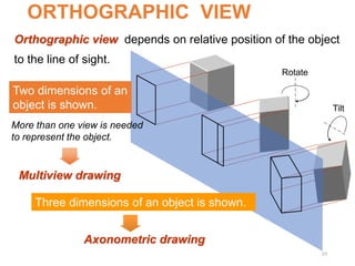
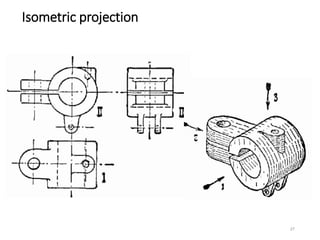
1. Orthographic views show objects from different angles including top, front, side, and section views.
2. Pictorial views like isometric drawings show a 3D appearance but distort some dimensions.
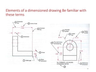
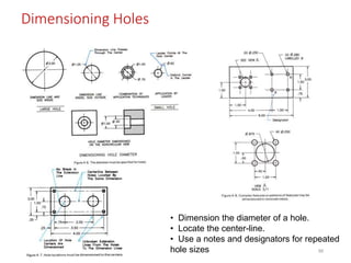
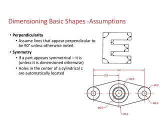
3. Dimensioning and tolerancing provide critical size and shape specifications.
4. Traditional tools like T-squares, compasses, and templates were used to manually create accurate drawings, while modern software allows computer-generated drawings.
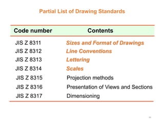
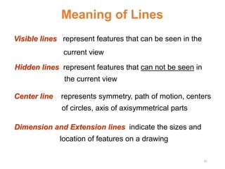
5. Standards ensure consistency in layout, line types, lettering and other elements so drawings are clear to all readers.