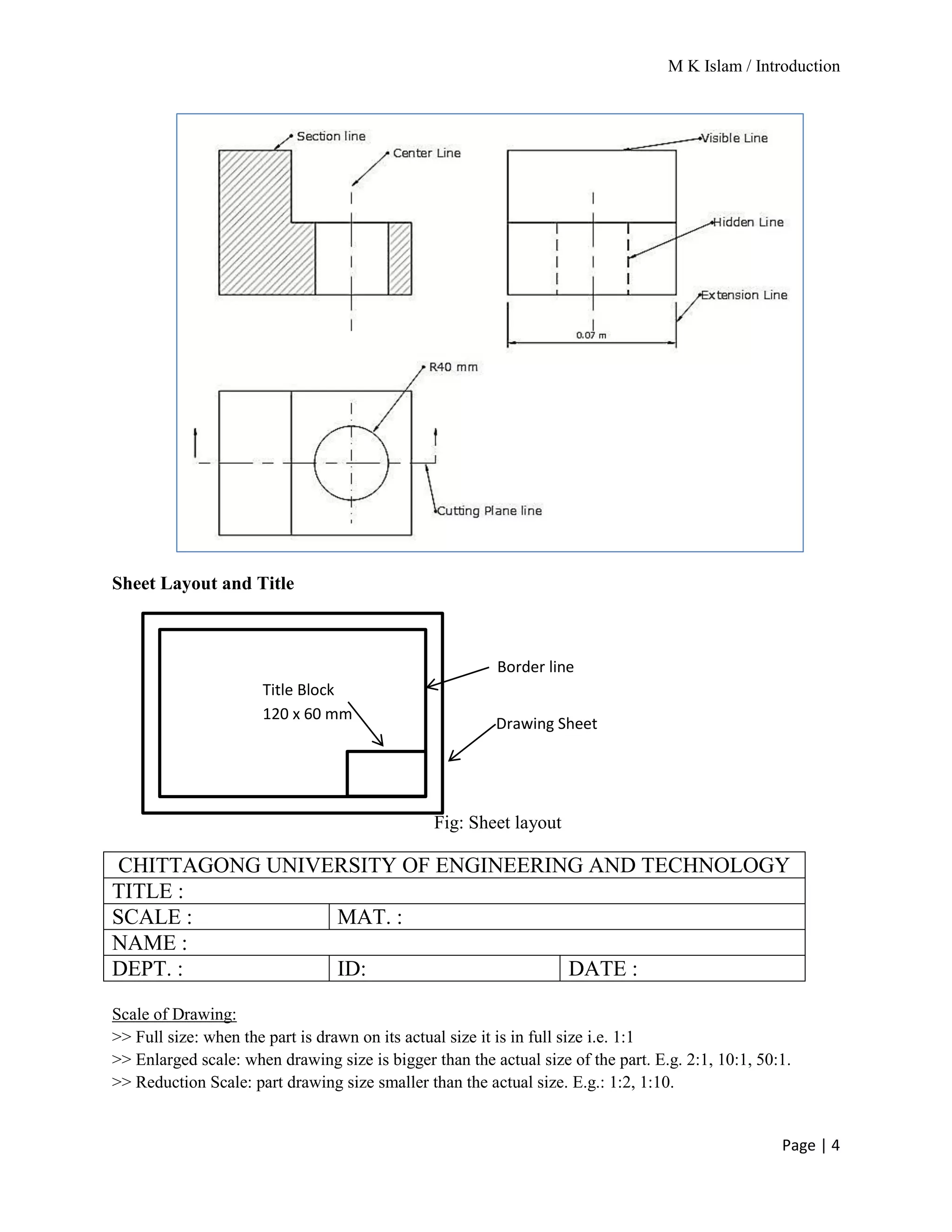
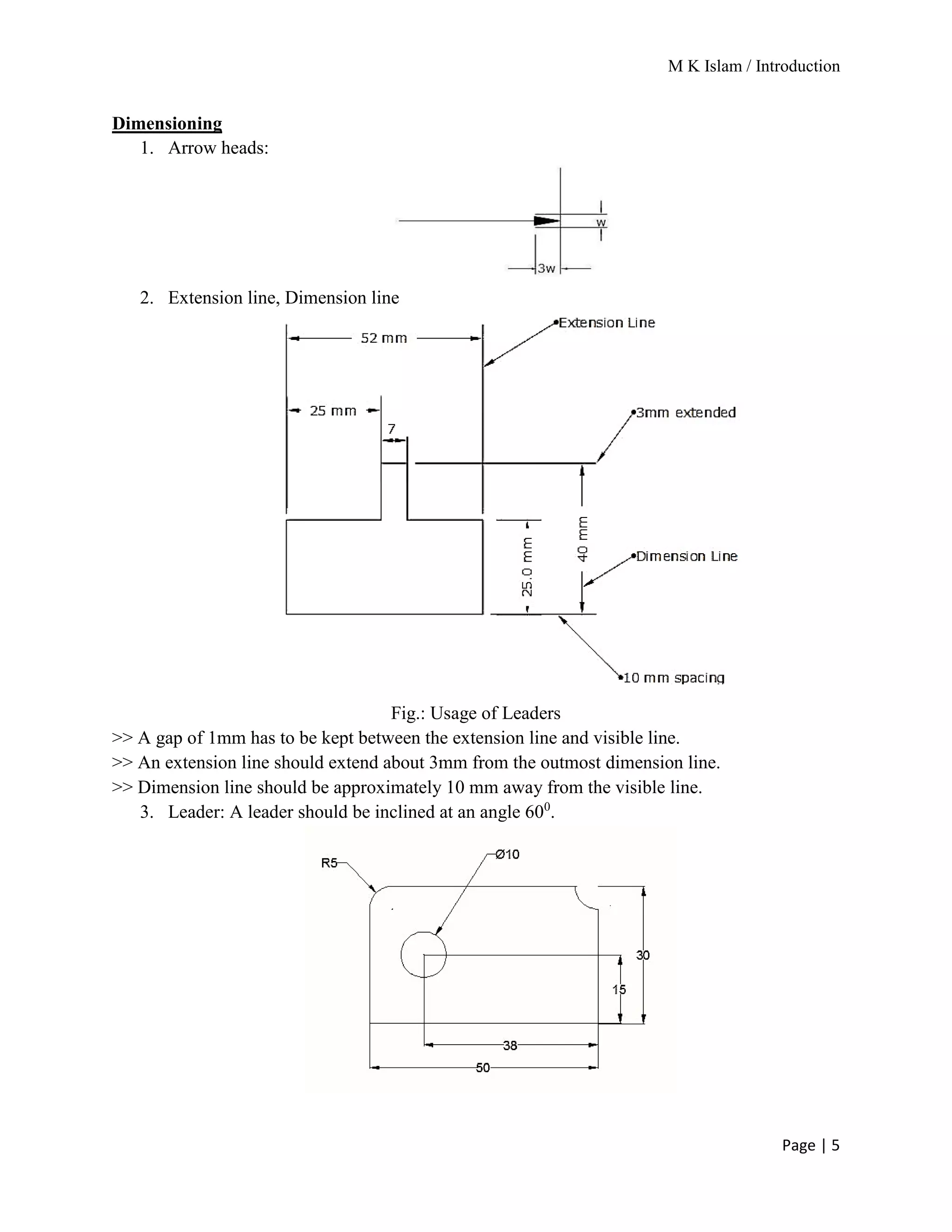
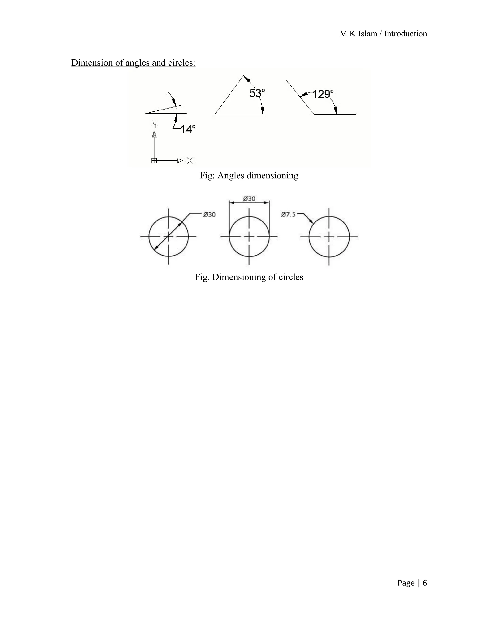
M K Islam / Introduction
Page | 1
Mechanical Drawing
A drawing is a graphic representation of real thing or an idea. It is the communication medium
between the various persons involved in the design and manufacturer of machines, buildings,
bridges, etc. It is also called graphic language.
Mechanical drawing is one class of engineering drawing that is used to manufacture the various
machine elements.
The graphic language had its existence when it became necessary to build new structures and
create new machines or the like, in addition to representing the existing ones. In the absence of
graphic language, the ideas on technical matters have to be conveyed by speech or writing, both
are unreliable and difficult to understand by the shop floor people for manufacturing. This
method involves not only lot of time and labor, but also manufacturing errors. Without
engineering drawing, it would have been impossible to produce objects such as aircrafts,
automobiles, locomotives, etc., each requiring thousands of different components.
Drawing instruments:
1. Drawing board: Drawing board is used for placing the drawing paper on it with the help
of either cellophane tape or board pin. Drafting table can be used also.
Fig.: Drawing board and Table
2. T-Square (T scale): T-Square is used to draw horizontal line. It is used on a drawing
board. It must be made of transparent plastic. The head of the T-square is placed on the
left edge of the board for the right handed person and vice versa.
Fig.: T-Square
M K Islam / Introduction
Page | 2
3. Triangles / Set squares : Triangles are set of 450 and 300 -600 triangles which are made
of clear plastic. They are used together with the straightedge of the T-square to draw
vertical and inclined lines.
Fig. : Triangles
4. Scales: Scales are used for measurement only, not for drawing lines.
5. Compasses:Compasses are used to draw a circle or an arc. Most common type compasses
are Friction head compass and Drop bow compass.
Fig.: Pencil Compass
6. Protractor: Angles can be measured with this tool.
Fig.: Protector
7. Paper: Drawing paper / Art paper are used for drafting.
8. Pencils and leads: HB and 2B/3B pencils are used to draw. 0.5mm lead can be used also.
M K Islam / Introduction
Page | 3
Types of Lines and their use
Sl
#
Types of lines Usage
1. Continuous
line(thick)
Visible outline
of the object
2. Continuous
line(thin)
Dimension
lines,
Projection
lines, Leader
lines, Hatching
lines.
3. Long break
line
To show a
break on the
object
Short break
line
4. Hidden line/
dashed line
To represent
the hidden
edge of an
object
5. Center line To show the
center lines of
the holes
6. Extension
line
To show
dimension of
an object
7. Section line To indicate the
cut portion of
an object
8. Cutting plane
line
To show the
imaginary
cutting line
M K Islam / Introduction
Page | 4
Sheet Layout and Title
Fig: Sheet layout
CHITTAGONG UNIVERSITY OF ENGINEERING AND TECHNOLOGY
TITLE :
SCALE : MAT. :
NAME :
DEPT. : ID: DATE :
Scale of Drawing:
>> Full size: when the part is drawn on its actual size it is in full size i.e. 1:1
>> Enlarged scale: when drawing size is bigger than the actual size of the part. E.g. 2:1, 10:1, 50:1.
>> Reduction Scale: part drawing size smaller than the actual size. E.g.: 1:2, 1:10.
Title Block
120 x 60 mm
Border line
Drawing Sheet
M K Islam / Introduction
Page | 5
Dimensioning
1. Arrow heads:
2. Extension line, Dimension line
Fig.: Usage of Leaders
>> A gap of 1mm has to be kept between the extension line and visible line.
>> An extension line should extend about 3mm from the outmost dimension line.
>> Dimension line should be approximately 10 mm away from the visible line.
3. Leader: A leader should be inclined at an angle 600
.
M K Islam / Introduction
Page | 6
Dimension of angles and circles:
Fig: Angles dimensioning
Fig. Dimensioning of circles

Introduction to Engineering Drawing

  • 1.
    M K Islam/ Introduction Page | 1 Mechanical Drawing A drawing is a graphic representation of real thing or an idea. It is the communication medium between the various persons involved in the design and manufacturer of machines, buildings, bridges, etc. It is also called graphic language. Mechanical drawing is one class of engineering drawing that is used to manufacture the various machine elements. The graphic language had its existence when it became necessary to build new structures and create new machines or the like, in addition to representing the existing ones. In the absence of graphic language, the ideas on technical matters have to be conveyed by speech or writing, both are unreliable and difficult to understand by the shop floor people for manufacturing. This method involves not only lot of time and labor, but also manufacturing errors. Without engineering drawing, it would have been impossible to produce objects such as aircrafts, automobiles, locomotives, etc., each requiring thousands of different components. Drawing instruments: 1. Drawing board: Drawing board is used for placing the drawing paper on it with the help of either cellophane tape or board pin. Drafting table can be used also. Fig.: Drawing board and Table 2. T-Square (T scale): T-Square is used to draw horizontal line. It is used on a drawing board. It must be made of transparent plastic. The head of the T-square is placed on the left edge of the board for the right handed person and vice versa. Fig.: T-Square
  • 2.
    M K Islam/ Introduction Page | 2 3. Triangles / Set squares : Triangles are set of 450 and 300 -600 triangles which are made of clear plastic. They are used together with the straightedge of the T-square to draw vertical and inclined lines. Fig. : Triangles 4. Scales: Scales are used for measurement only, not for drawing lines. 5. Compasses:Compasses are used to draw a circle or an arc. Most common type compasses are Friction head compass and Drop bow compass. Fig.: Pencil Compass 6. Protractor: Angles can be measured with this tool. Fig.: Protector 7. Paper: Drawing paper / Art paper are used for drafting. 8. Pencils and leads: HB and 2B/3B pencils are used to draw. 0.5mm lead can be used also.
  • 3.
    M K Islam/ Introduction Page | 3 Types of Lines and their use Sl # Types of lines Usage 1. Continuous line(thick) Visible outline of the object 2. Continuous line(thin) Dimension lines, Projection lines, Leader lines, Hatching lines. 3. Long break line To show a break on the object Short break line 4. Hidden line/ dashed line To represent the hidden edge of an object 5. Center line To show the center lines of the holes 6. Extension line To show dimension of an object 7. Section line To indicate the cut portion of an object 8. Cutting plane line To show the imaginary cutting line
  • 4.
    M K Islam/ Introduction Page | 4 Sheet Layout and Title Fig: Sheet layout CHITTAGONG UNIVERSITY OF ENGINEERING AND TECHNOLOGY TITLE : SCALE : MAT. : NAME : DEPT. : ID: DATE : Scale of Drawing: >> Full size: when the part is drawn on its actual size it is in full size i.e. 1:1 >> Enlarged scale: when drawing size is bigger than the actual size of the part. E.g. 2:1, 10:1, 50:1. >> Reduction Scale: part drawing size smaller than the actual size. E.g.: 1:2, 1:10. Title Block 120 x 60 mm Border line Drawing Sheet
  • 5.
    M K Islam/ Introduction Page | 5 Dimensioning 1. Arrow heads: 2. Extension line, Dimension line Fig.: Usage of Leaders >> A gap of 1mm has to be kept between the extension line and visible line. >> An extension line should extend about 3mm from the outmost dimension line. >> Dimension line should be approximately 10 mm away from the visible line. 3. Leader: A leader should be inclined at an angle 600 .
  • 6.
    M K Islam/ Introduction Page | 6 Dimension of angles and circles: Fig: Angles dimensioning Fig. Dimensioning of circles