This document provides information about a course on Engineering Graphics taught at SSM Institute of Engineering and Technology. It includes the course objectives, outline, units of study, outcomes and references. The key points are:
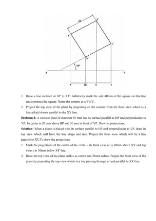
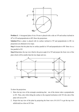
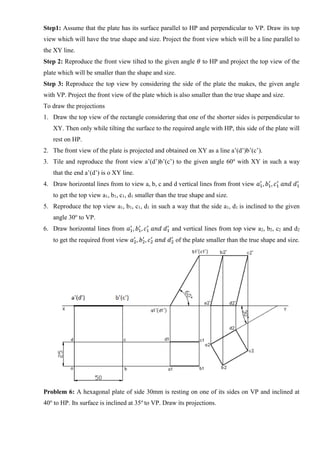
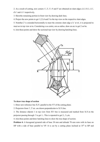
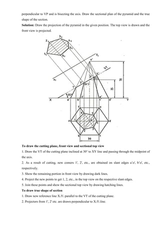
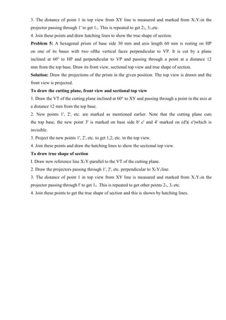
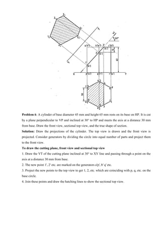
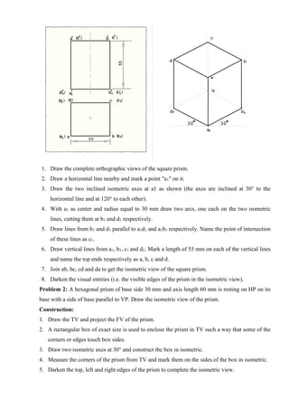
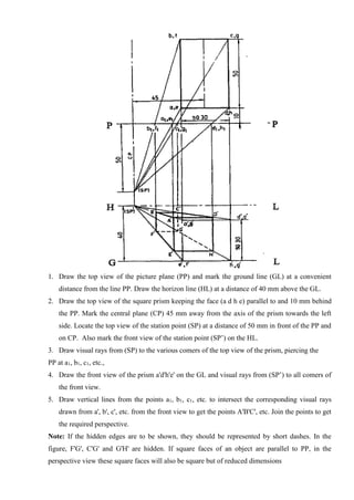
1. The course aims to develop graphic skills for communication and design. It covers topics like plane curves, projections, solids, developments and isometric/perspective views.
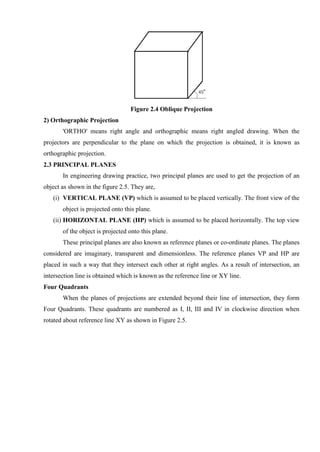
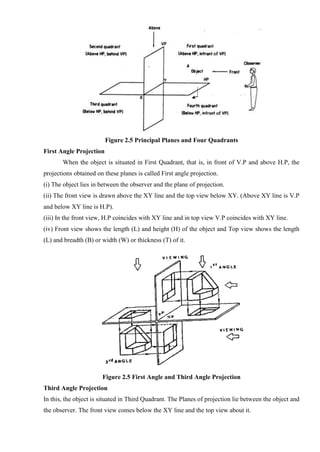
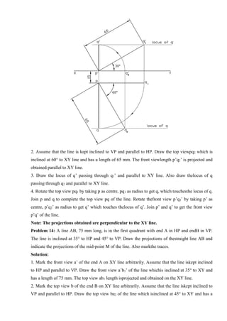
2. The course has 5 units spanning concepts, curves, projections of points/lines/surfaces, solids and their sections, and isometric/perspective projections.
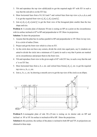
3. On completion, students will be able to sketch, project orthographically, draw solids and their developments, and visualize isometric and perspective views of objects

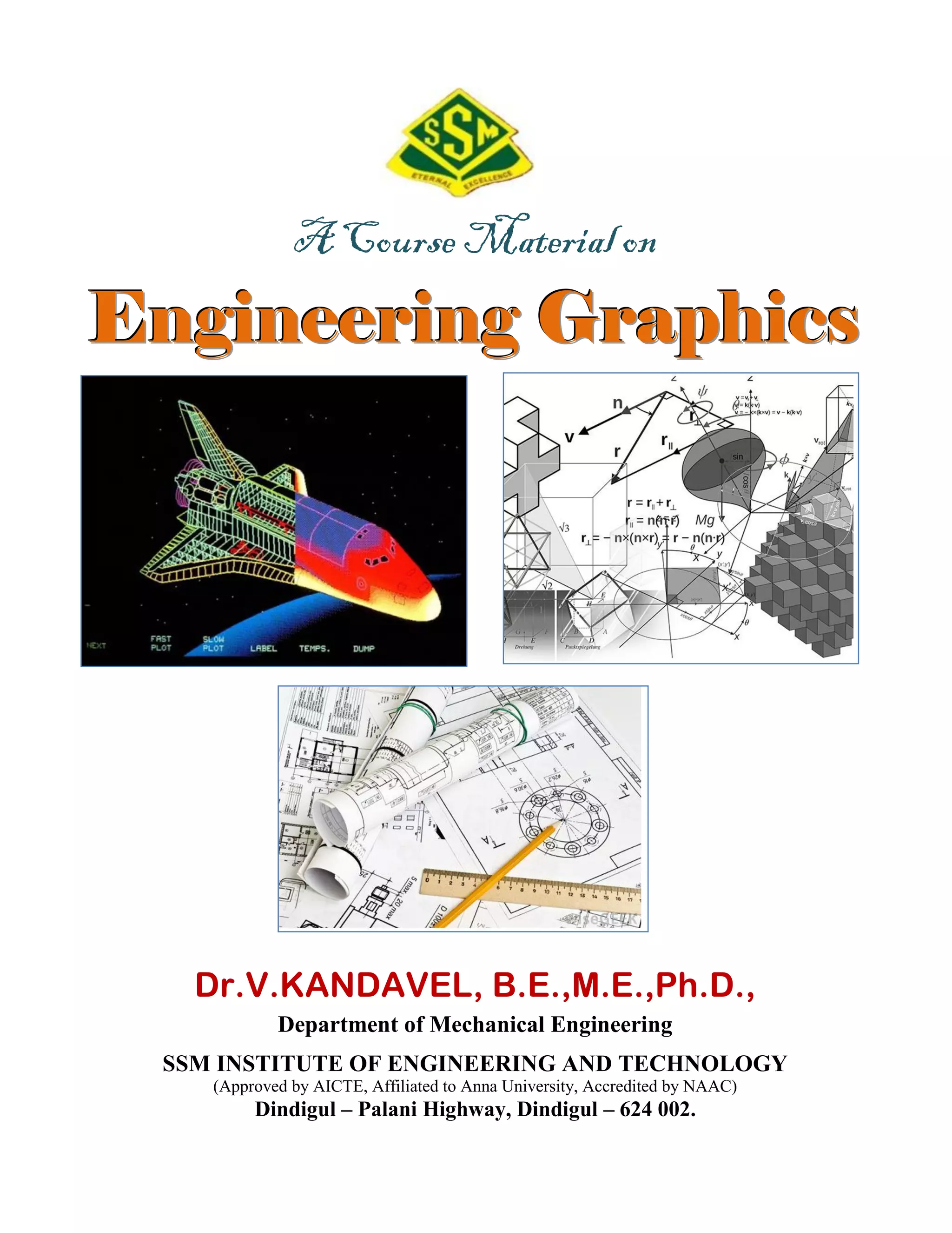
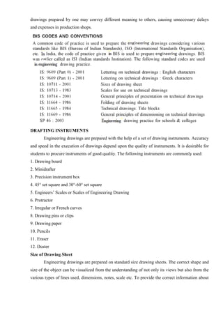
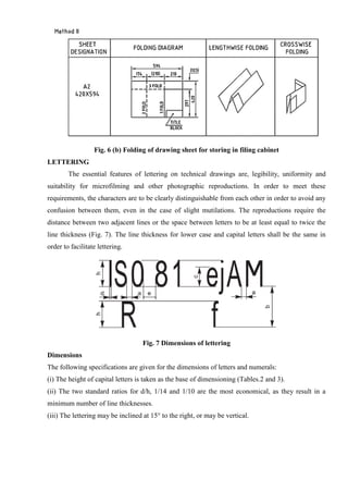
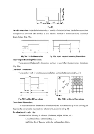
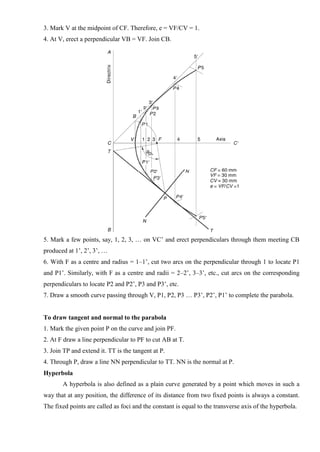
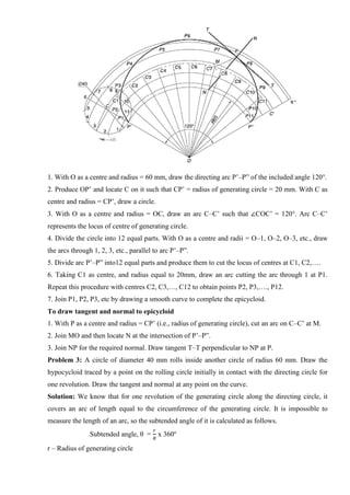
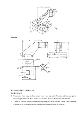
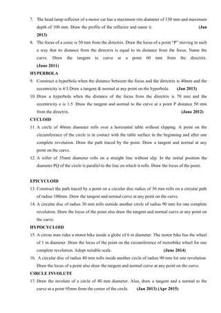
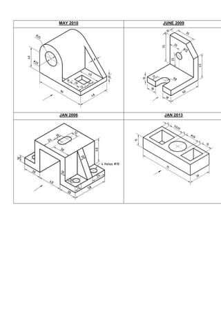
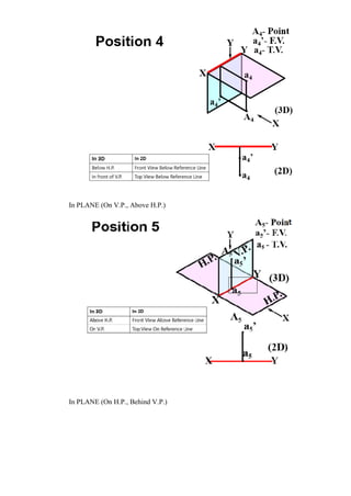
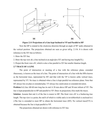
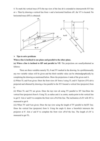
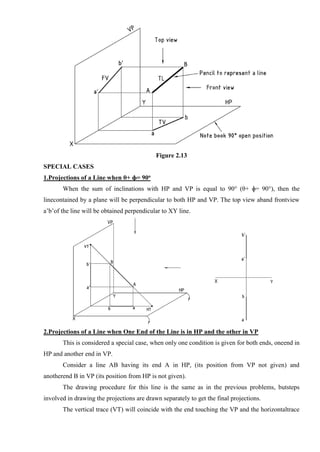
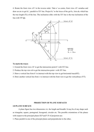
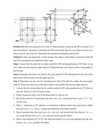
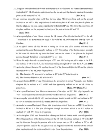
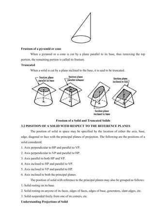
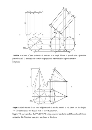
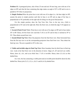
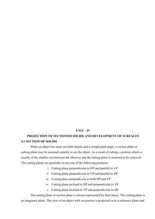
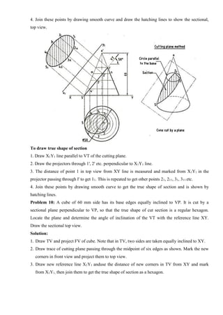
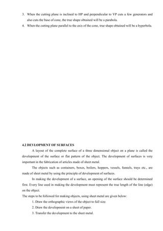
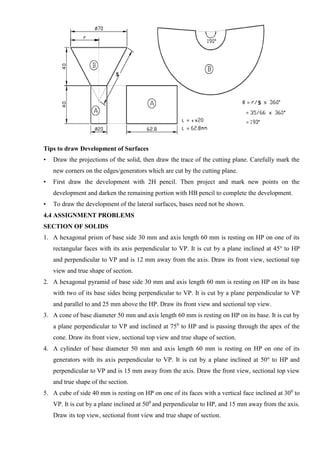
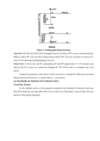
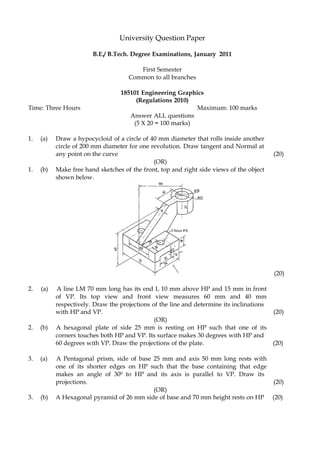
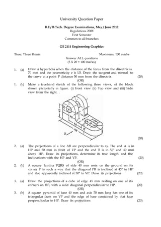
![Fig. 1.7 sketching a large circle
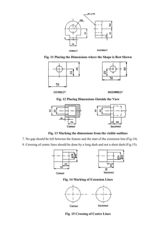
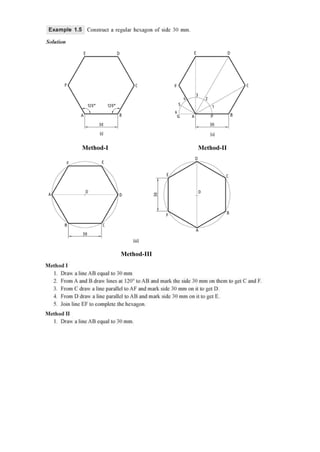
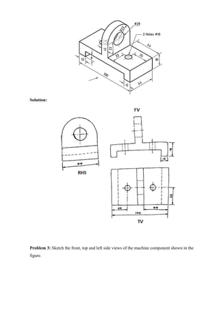
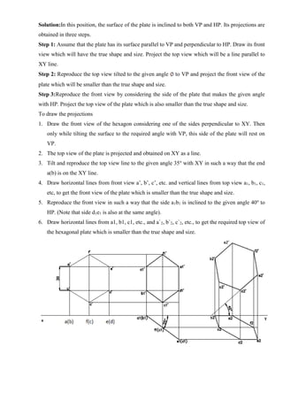
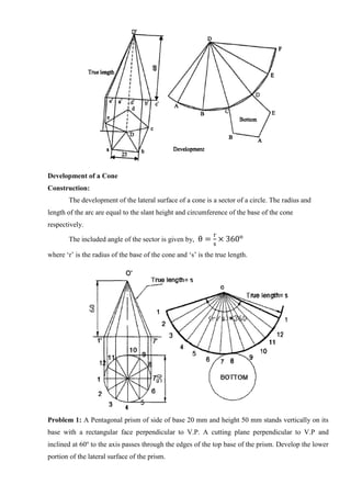
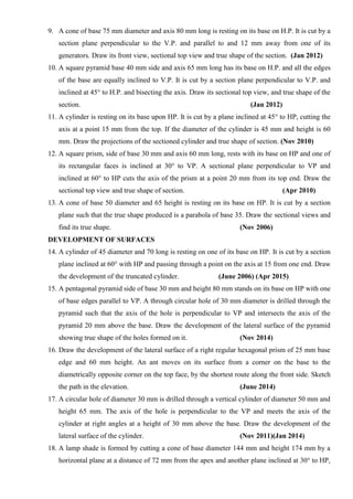
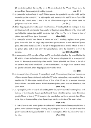
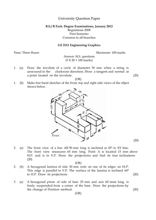
General Procedure to draw free hand sketches
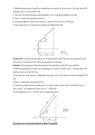
1. Mark their directions in the Pictorial View.
2. Measure the overall Length L, Width W and Height H of the object.
3. Using L, W and H, mark spaces for the front and Right Side Views in the form of rectangles [2H
Pencil].
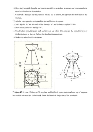
4. Mark the axes at the appropriate places [2H Pencil].
5. Sketch the details simultaneously in both Front and Right Side Views by drawing the
corresponding projects [2H Pencil].
6. Darken all the visible lines [HB Pencil].
7. Add the dimensions.
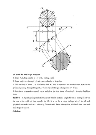
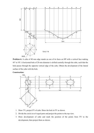
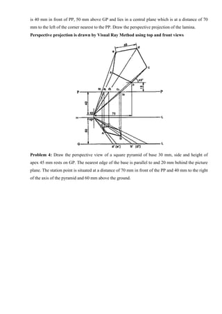
Problem 1: Sketch the front, top and left side views of an object shown in the figure.](https://image.slidesharecdn.com/egcoursematerialr-17vk-ssm-201209071353/85/Engineering-Graphics-course-material-R-17-vk-ssm-40-320.jpg)
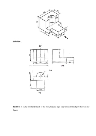
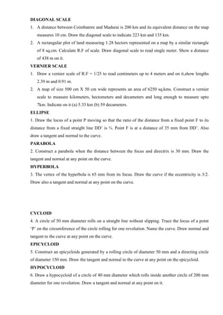
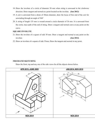
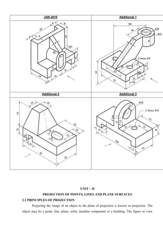
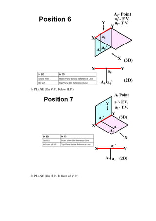
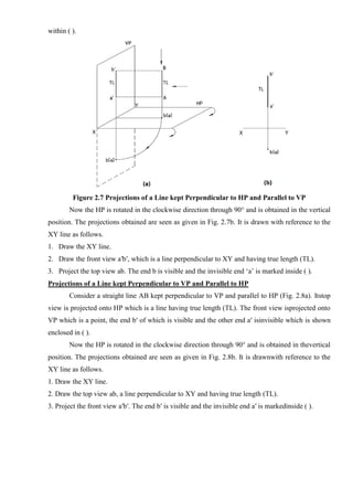
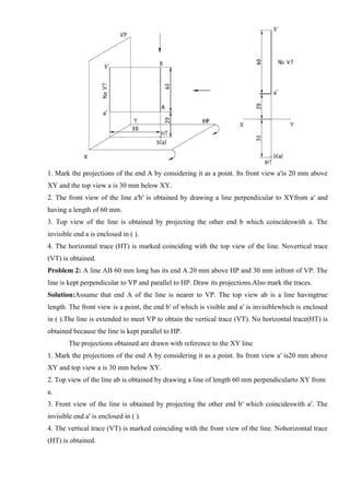
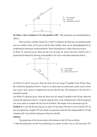
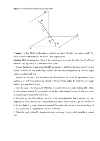
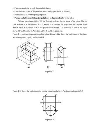
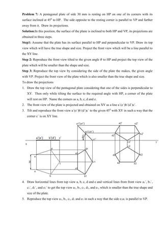
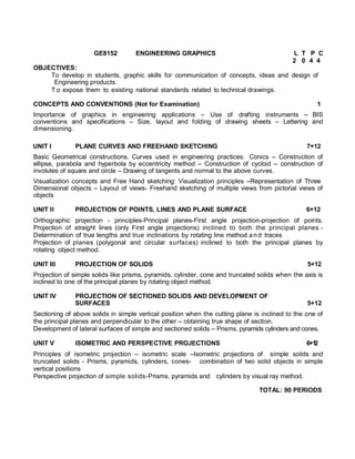
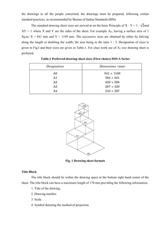
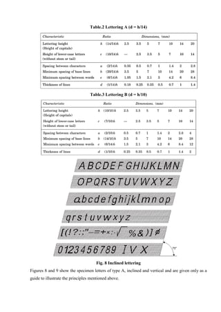
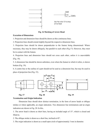
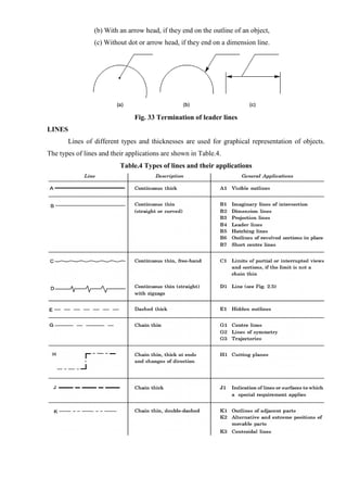
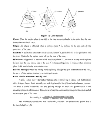
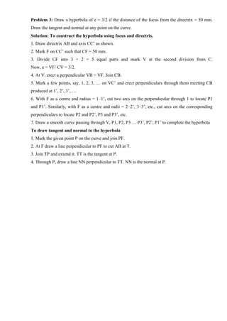
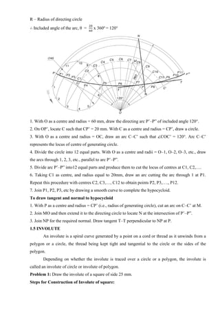
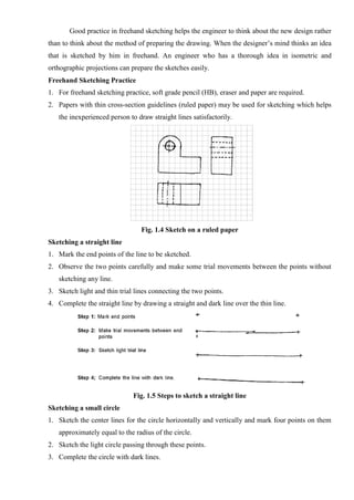
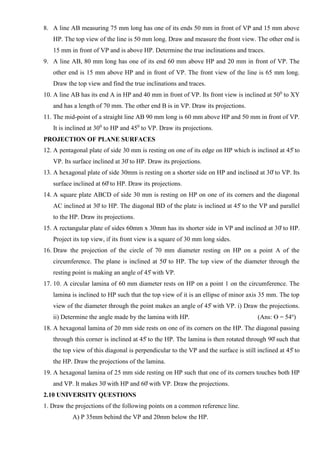
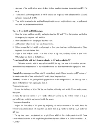
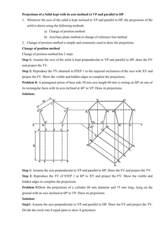
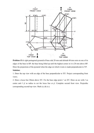
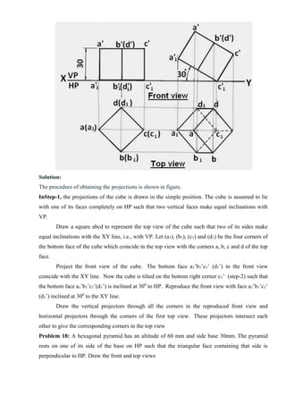
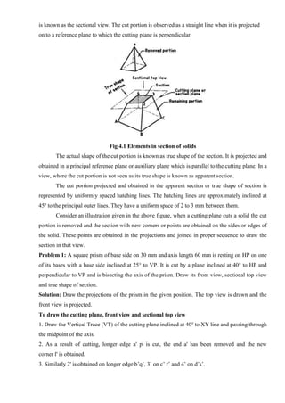
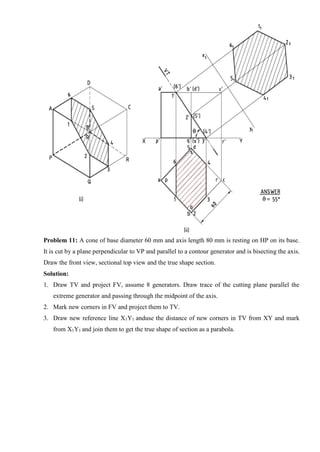
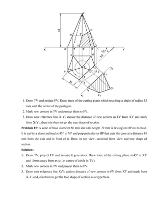
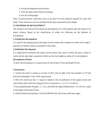
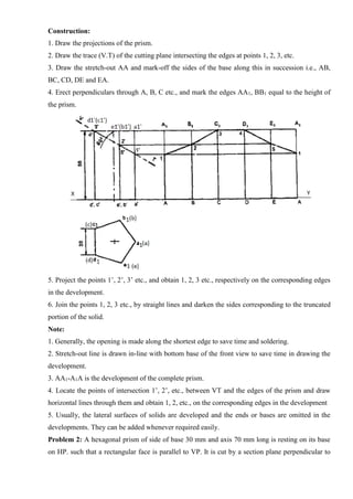
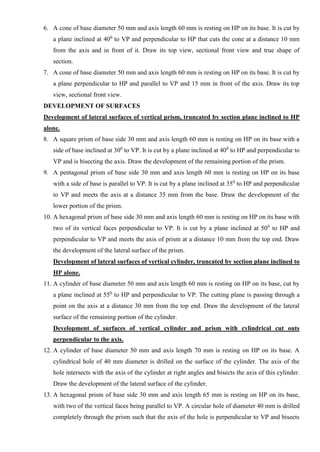
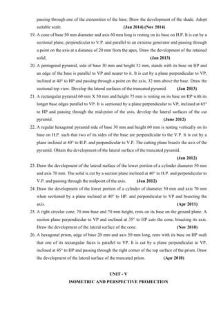
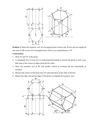
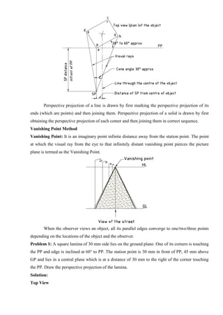
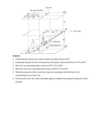
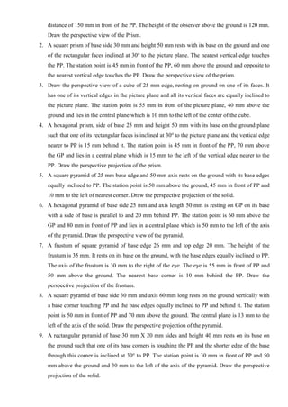
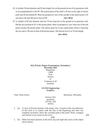
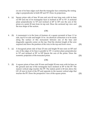
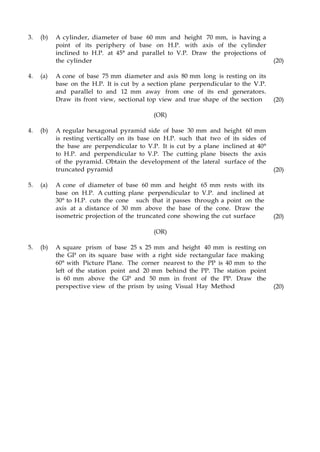
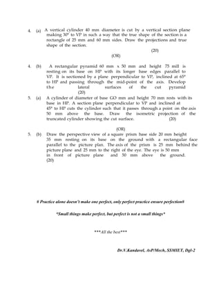
![7. Draw horizontal lines from a1`, b1`, c1` etc., and vertical lines from top view a2, b2, c2, etc., to
get the required front view a2`, b2`, c2`, etc., of the plane.
2.9 ASSIGNMENT PROBLEMS
PROJECTION OF LINES
1. A line AB 55 mm long has its end A 25 mm above HP and in VP. The line is inclined at 450
to
HP. Draw its projections.
2. A line AB 55 mm long has its end A 25 mm in front of VP and in HP. The line is inclined at
450
to VP. Draw its projections.
3. A line AB 75 mm long has its end A in both HP and VP. The line is kept inclined at 450
to HP
and 300
to VP. Draw its projections.
4. A line AB 85 mm long has its end A 25 mm away from both the reference planes and is in the
first quadrant. The line is inclined at 500
to HP and 300
to VP. Draw its projections and mark
the traces of the line.
5. A line AB 65 mm long has its end A 25 mm above HP and 15 mm in front of VP. The line is
inclined at 350
to HP and 550
to VP. Draw its projections.
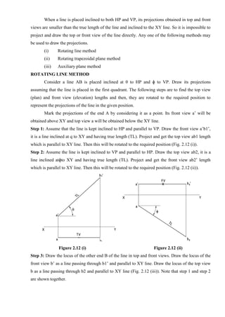
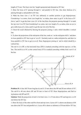
6. One end A of a line AB, 75 mm long is 20 mm above HP and 25 mm in front of VP. The line
inclined at 300
to HP and the top view makes 450
with VP. Draw the projections of the line and
find the true inclinations with the vertical plane. [Ans:Ø = 380]
7. A line AB 85 mm long has its end A 60 mm above HP and 65 mm in front of VP. The end B is
25 mm above HP and 20 mm in front of the VP. Draw the projections and find its inclinations
with HP and VP. Mark its traces. [Ans:θ = 240, Ø = 320]](https://image.slidesharecdn.com/egcoursematerialr-17vk-ssm-201209071353/85/Engineering-Graphics-course-material-R-17-vk-ssm-103-320.jpg)
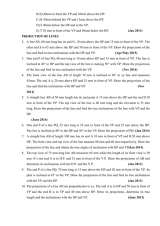
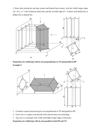
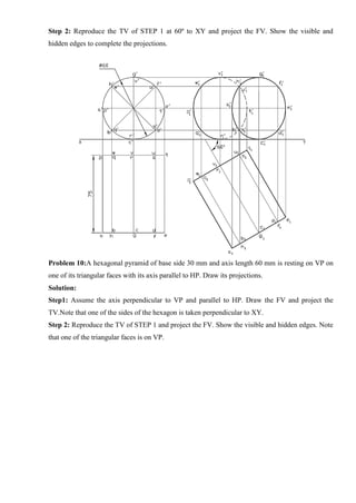
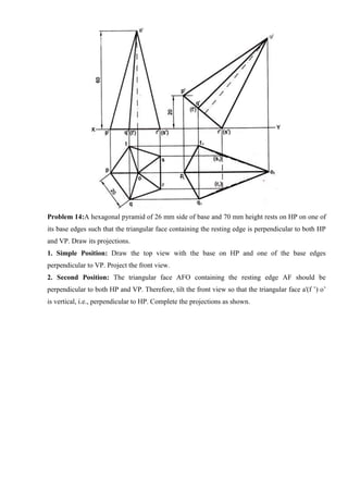
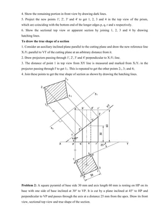
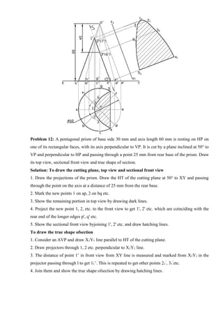
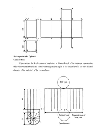

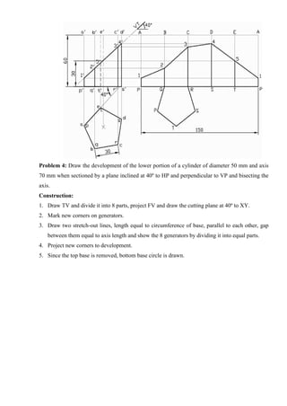
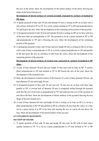
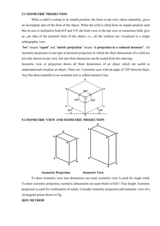
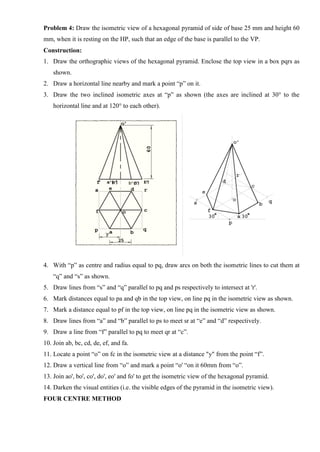
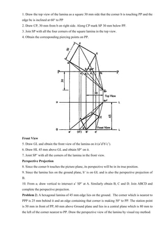
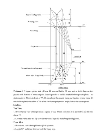
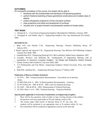
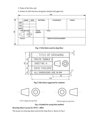
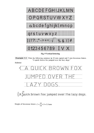
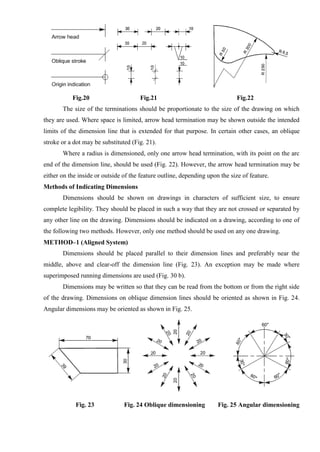
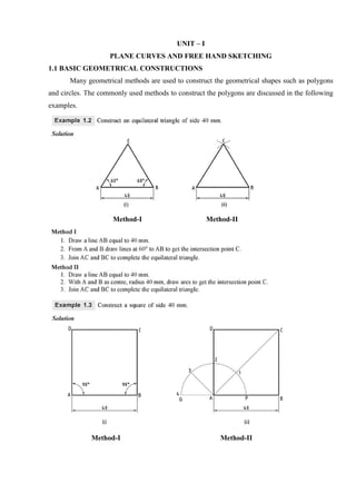
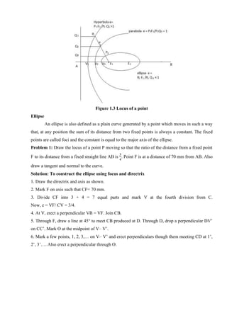
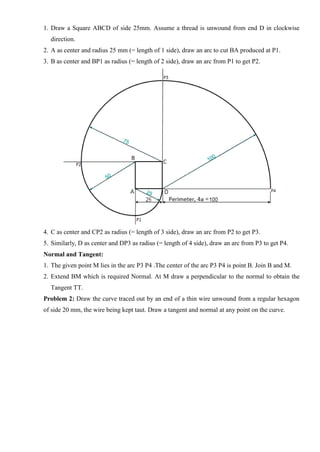
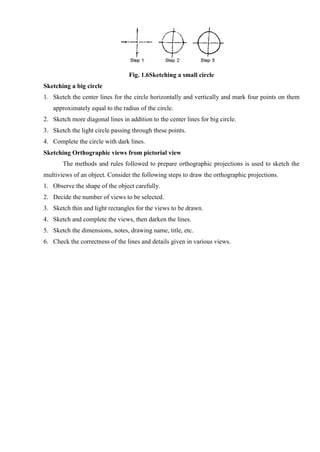
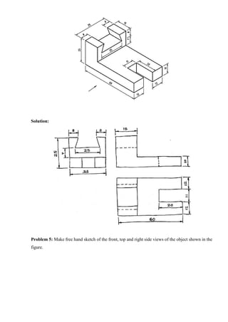
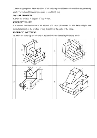
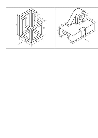
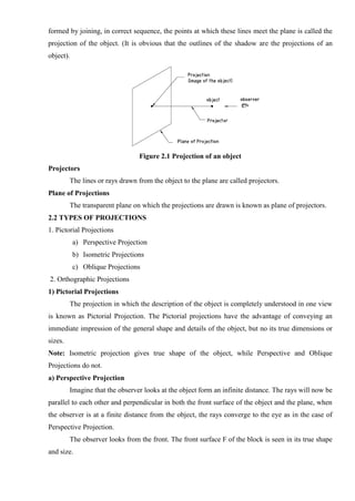
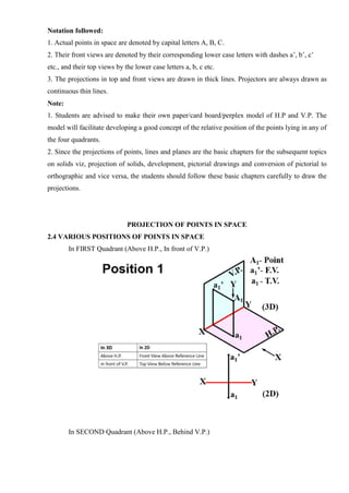
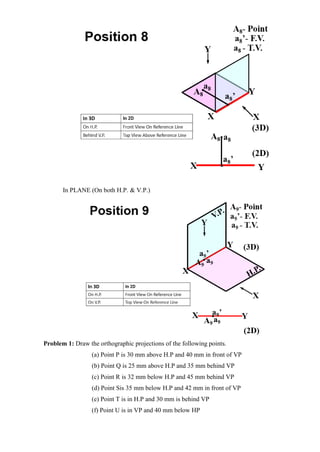
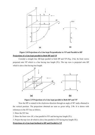
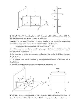
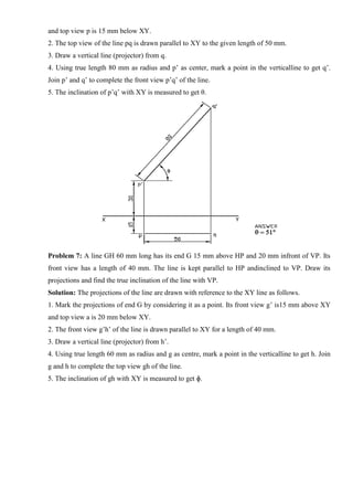
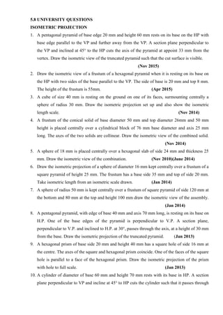
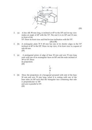
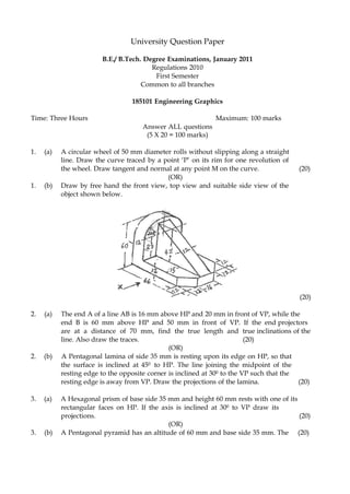
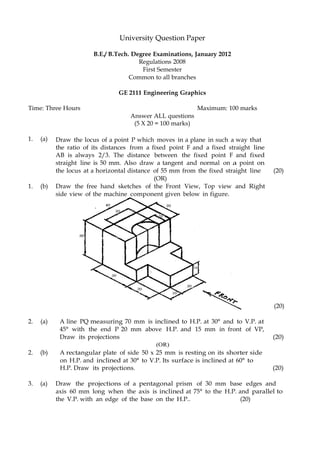
![Tips to draw Perspective Projection
1. The visible and invisible edges are usually identified through visualization.
2. The visible edges are marked by considering the edges in the front portion of the solid which
lie within the cone angle formed by the visual rays in top view with SP.
3. The details printed in figure are neglected by the users while preparing the fair drawing of
perspective.
4. Complete the perspective projection by drawing dark lines for the visible portion of the object.
5.7 ASSIGNMENT PROBLEMS
ISOMETRIC PROJECTIONS
1. Draw the isometric view of a regular hexagon of side 30 mm placed with its surface parallel to
HP and a side perpendicular to VP.
2. Draw the isometric view of a circular lamina of diameter 40 mm placed with surface parallel to
HP.
3. Draw the isometric view of a regular hexagon of side 30 mm placed with its surface parallel to
VP and a side perpendicular to HP.
4. Draw the isometric view of a circular lamina of diameter 40 mm placed with its surface
parallel to VP.
5. Draw the isometric projection of a circle of diameter 40 mm by placing its surface (i) parallel
to HP (ii) parallel to VP.
ISOMETRIC PROJECTION OF SOLIDS LIKE PRISM, PYRAMID, CYLINDER AND
CONE.
6. A hexagonal prism of base side 30 mm and axis length 60 mm is resting on HP on its base with
a side of base parallel to VP. Draw the isometric view of the prism.
7. Draw the isometric view of a hexagonal pyramid of base side 30 mm and axis length 60 mm
that is resting on HP on its base.
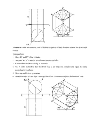
8. Draw the isometric view of a vertical cylinder of base diameter 50 mm and axis length 60 mm.
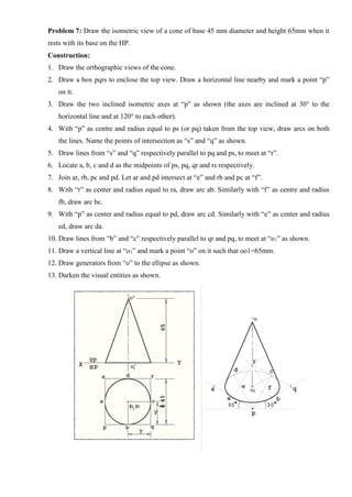
9. Draw the isometric view of a cone of base diameter 50 mm and axis length 60 mm resting on
HP on its base.
10. Draw the isometric projection of a frustum of a cone of base diameter 60 mm, top base
diameter and axis length 50 mm rests on HP on its base.
[Note: The top and front views are always constructed with isometric lengths to draw the isometric
projection]
ISOMETRIC PROJECTION - WHEN PYRAMID IS IN SIMPLE VERTICAL POSITION,
BY A CUTTING PLANE INCLINED TO HP.](https://image.slidesharecdn.com/egcoursematerialr-17vk-ssm-201209071353/85/Engineering-Graphics-course-material-R-17-vk-ssm-205-320.jpg)
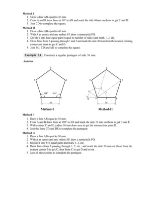
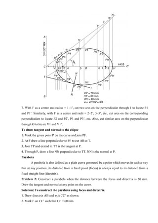
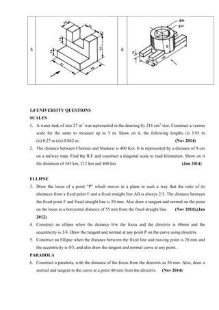
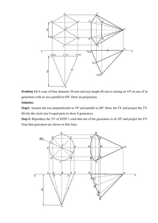
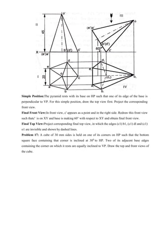
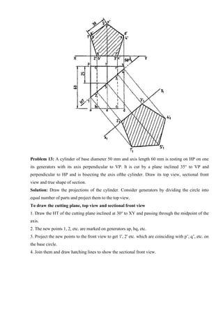
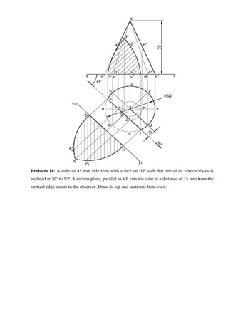
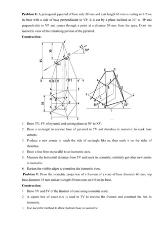
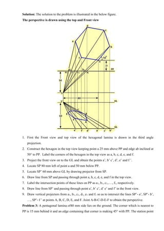
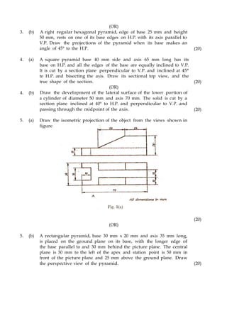
![11. A pentagonal pyramid of base side 30 mm and axis length 65 mm is resting on HP on its base
with a side of base perpendicular to VP. It is cut by a plane inclined at 300
to HP and
perpendicular to VP and passes through a point at a distance 30 mm from the apex. Draw the
isometric view of the remaining portion of the pyramid.
ISOMETRIC PROJECTION - WHEN CONE IS IN SIMPLE VERTICAL POSITION, BY
A CUTTING PLANE INCLINED TO HP.
12. A cone of base diameter 50 mm and height 70 mm stands on HP with its base. It is cut by a
cutting plane inclined at 300
to HP cutting the axis of the cone at a height of 40 mm from its
base. Draw the isometric view of the remaining part of the cone.
ISOMETRIC PROJECTION OF COMBINATION OF ANY TWO SOLIDS.
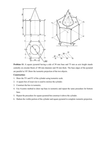
13. A square pyramid of side 30 mm, axis length 50 mm is centrally placed on top of a cube of side
50 mm. Draw the isometric projection of the solids.
[Note: The top and front views of the solids are always drawn in isometric dimensions to draw the
isometric projection of the solids]
14. A cone of base diameter 40 mm and axis length 50 mm is mounted centrally on the top of a
square slab of side 60 mm and thickness 15 mm. Draw the isometric projection of the solids.
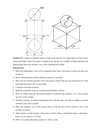
15. Draw the isometric projection of a hexagonal prism of side of base 35 mm and altitude 50 mm
surmounting a tetrahedron of side 45 mm such that the axes of the solid are collinear and at
least one of the edges of the two solids are parallel.
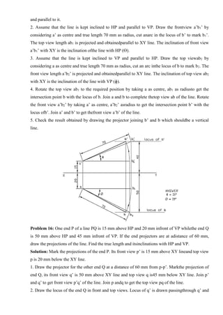
16. A cone of base diameter 30 mm and height 40 mm rests centrally over a frustum of a
hexagonal pyramid of base side 40 mm, top base side 25 mm and height 60 mm. Draw the
isometric projection of the solids.
17. A frustum of a cone having 25 mm as top diameter, 50 mm as bottom diameter and 50 mm axis
length is placed vertically on a cylindrical block of 75 mm diameter and is 25 mm thick such
that both the solids have the common axis. Draw the isometric projection of the combination of
these solids.
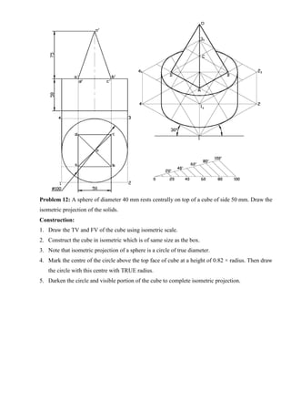
18. A sphere of diameter 40 mm rests centrally on top of a cube of side 50 mm. Draw the isometric
projection of the solids.
PERSPECTIVE PROJECTION
1. A rectangular prism 80 X 60 X 30 mm is placed on the ground behind the PP with the longest
edges vertical and the shortest edges receding to the left at an angle of 40o
to the PP. The
nearest vertical edge is 10 mm behind the PP and 15 mm to the left of the observer who is at a](https://image.slidesharecdn.com/egcoursematerialr-17vk-ssm-201209071353/85/Engineering-Graphics-course-material-R-17-vk-ssm-206-320.jpg)


![[Deck] What's New in Spark-Iceberg Integration via DSV2.pptx](https://cdn.slidesharecdn.com/ss_thumbnails/deckwhatsnewinspark-icebergintegrationviadsv2-260210005337-25955b12-thumbnail.jpg?width=640&height=640&fit=bounds)


