Downloaded 573 times
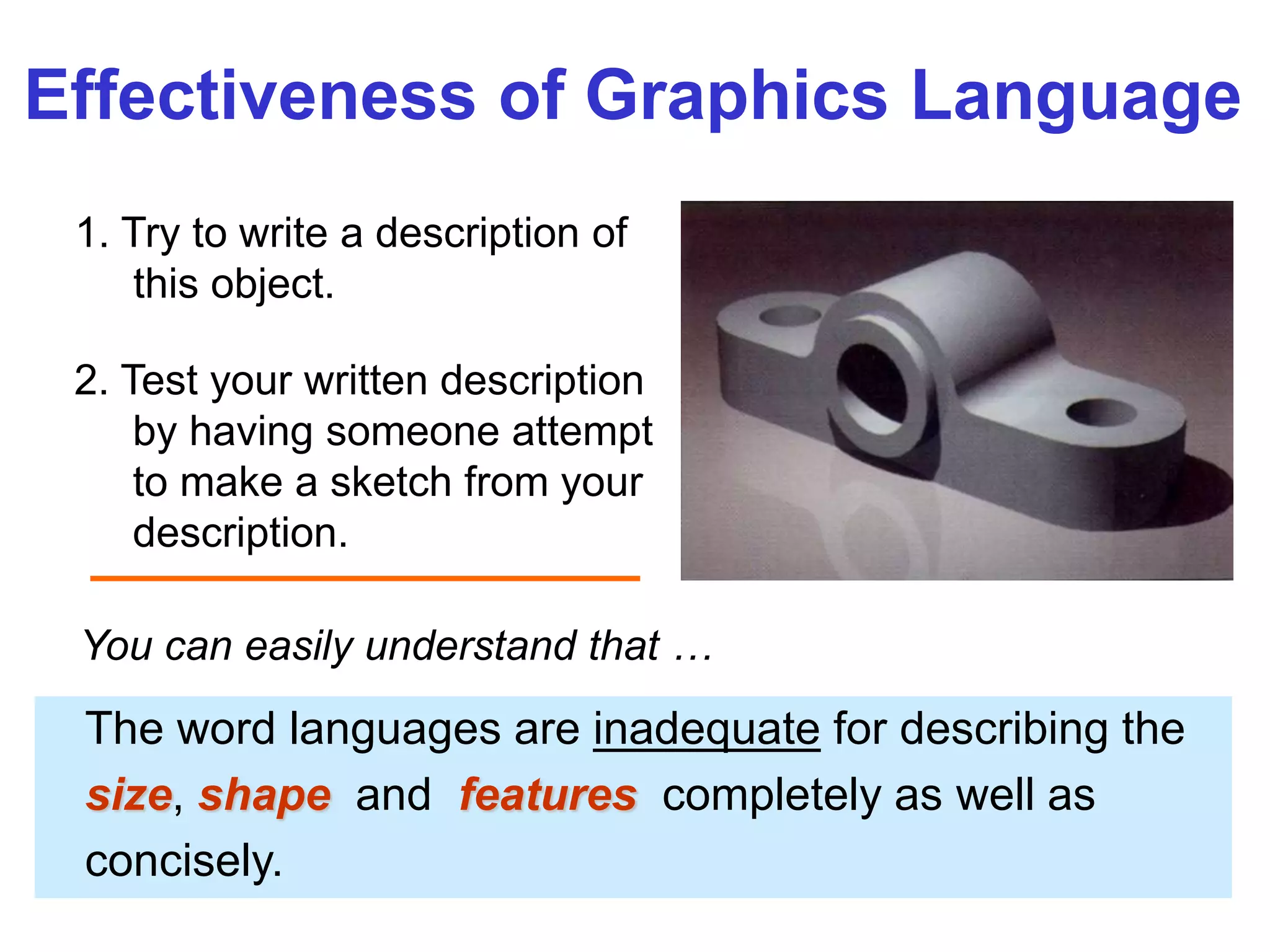
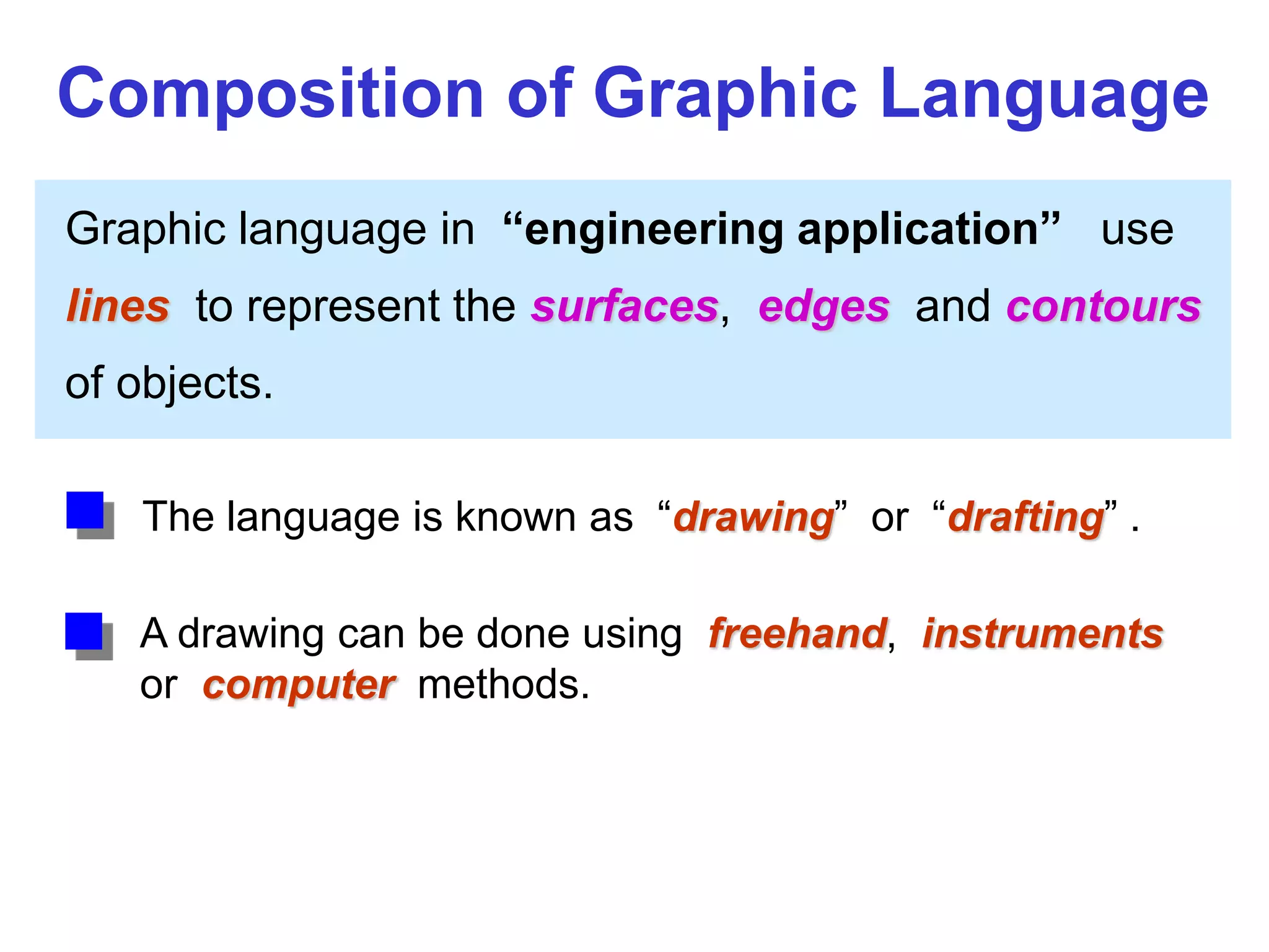
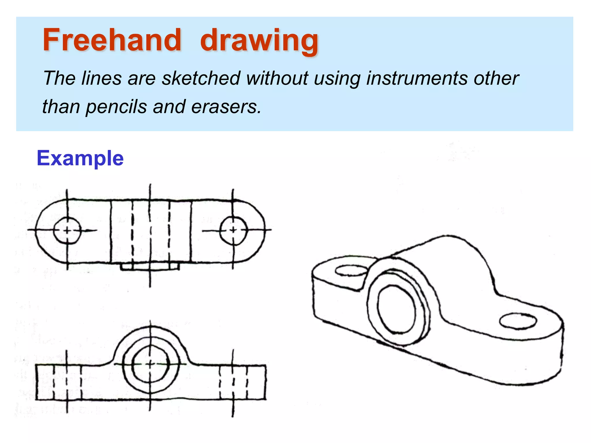
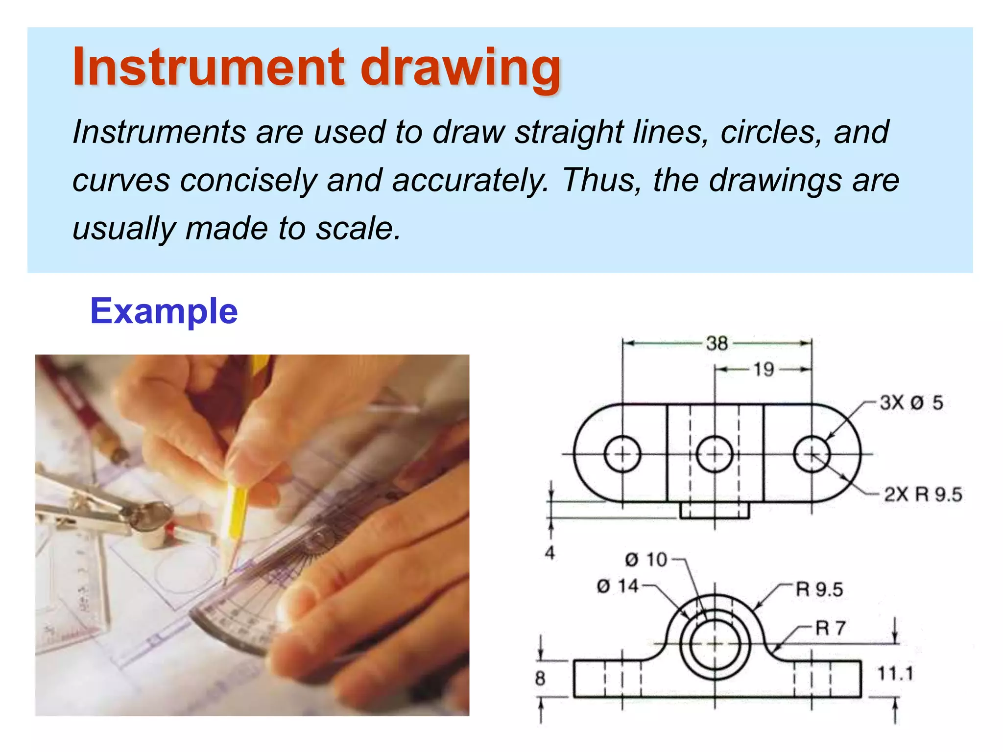
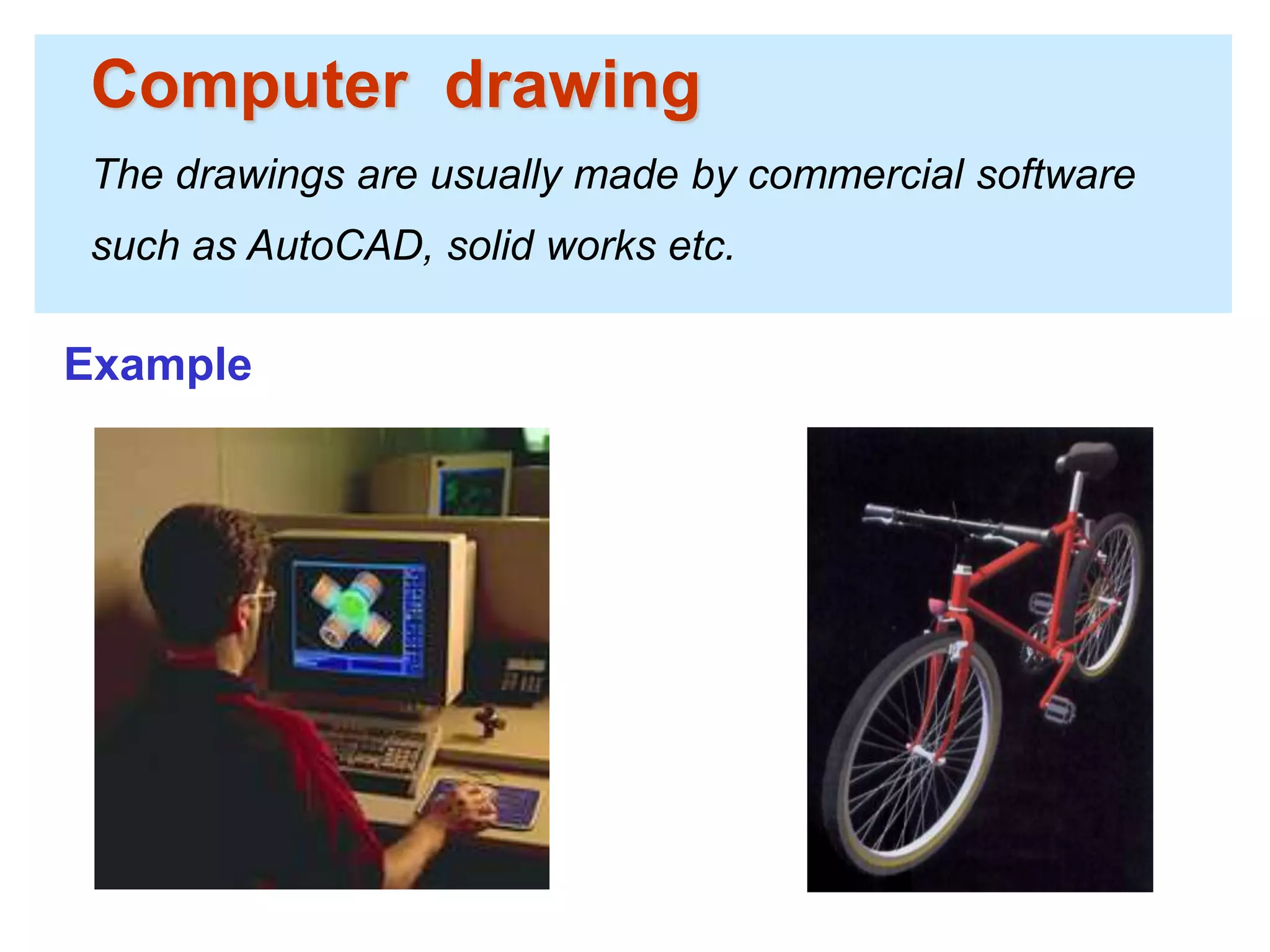
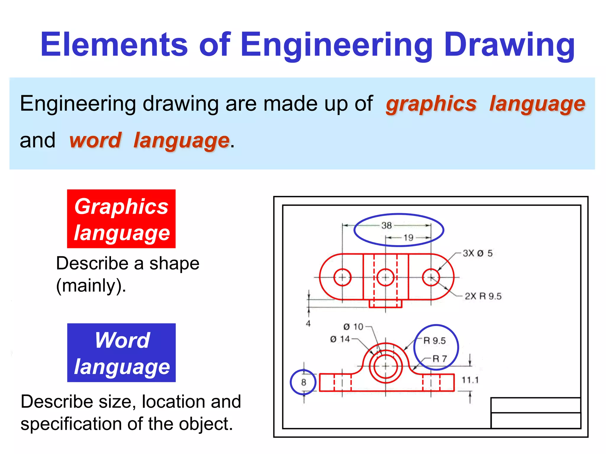
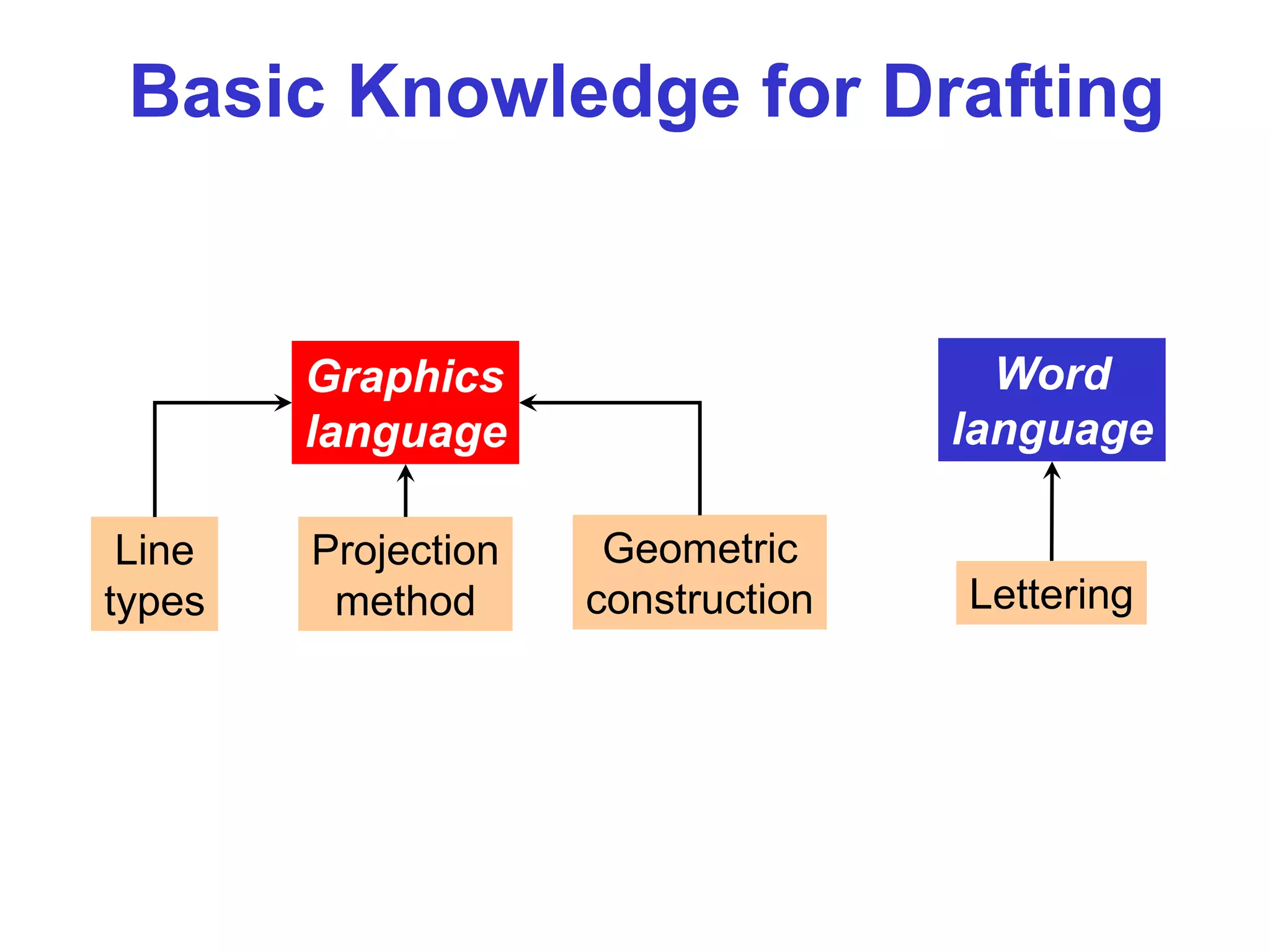
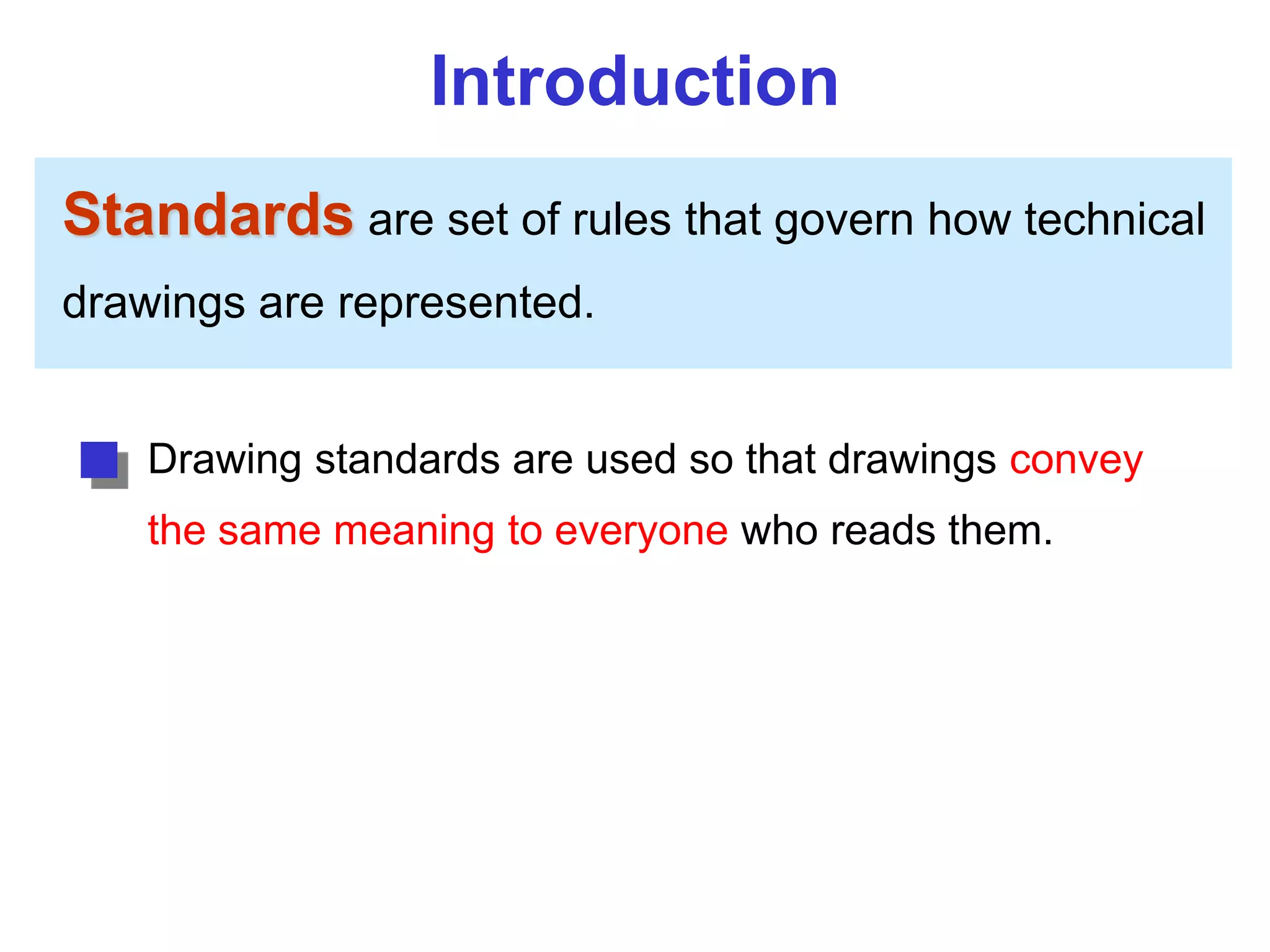
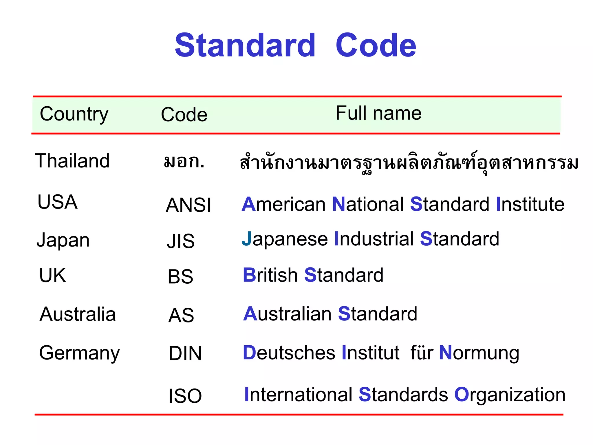
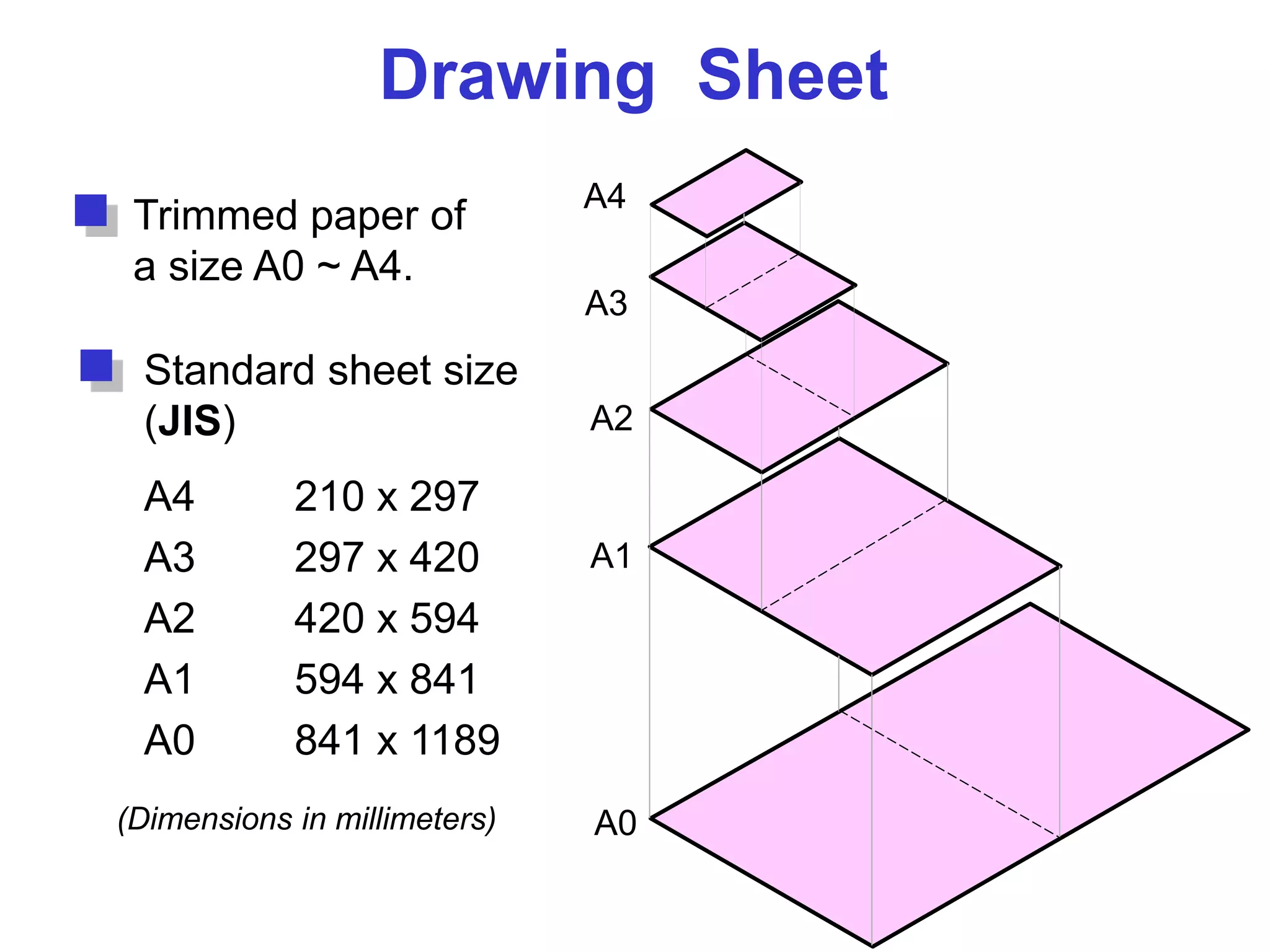
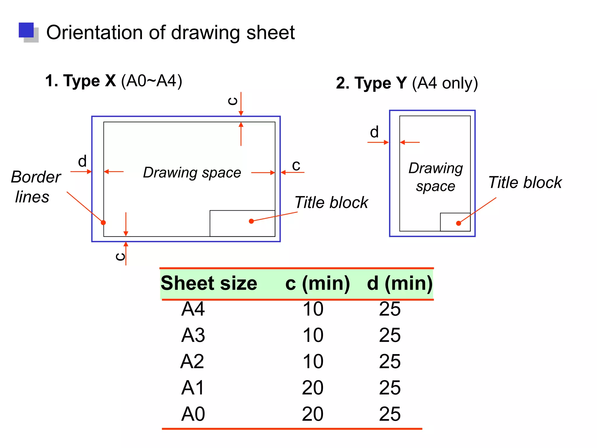
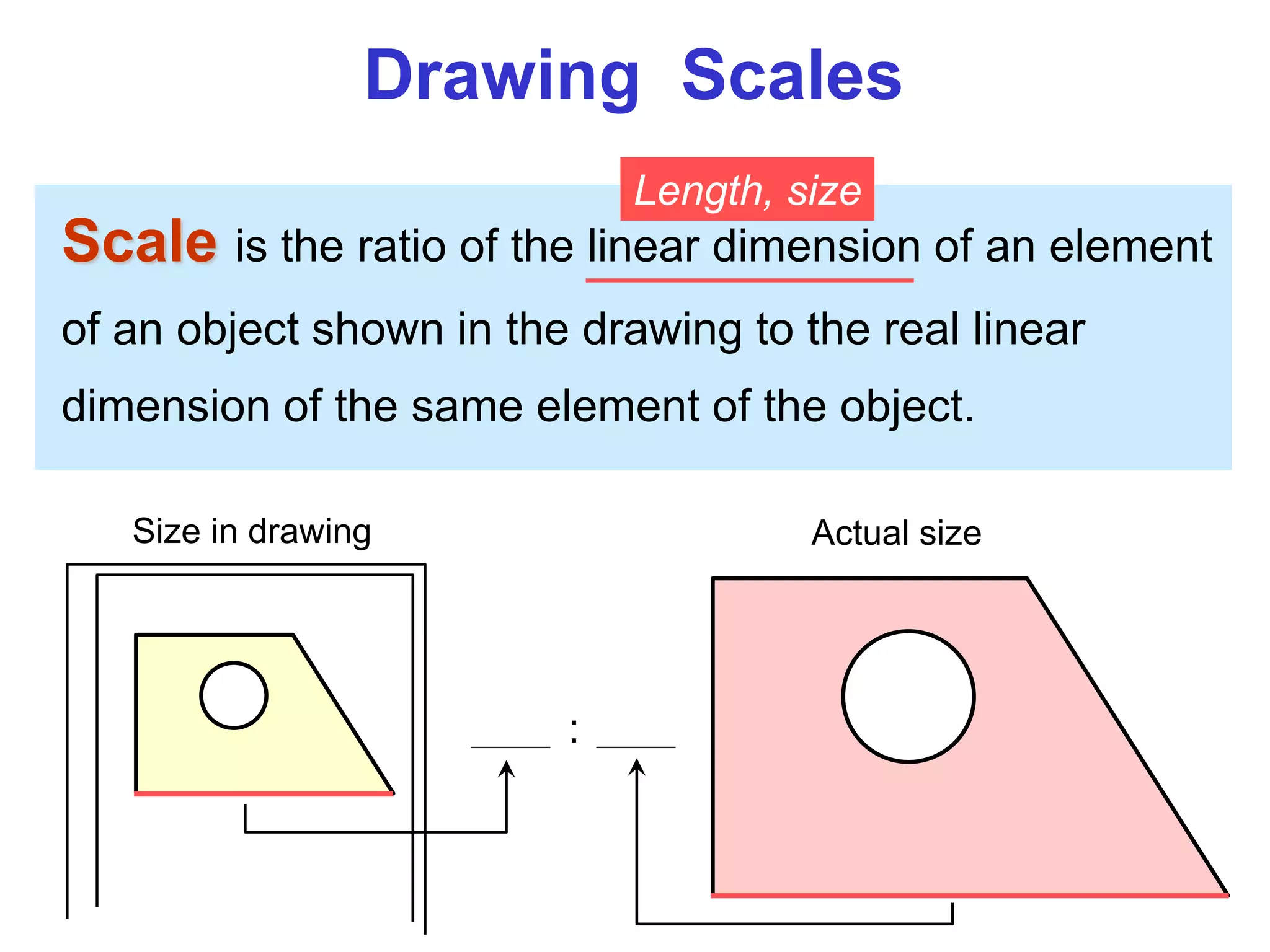
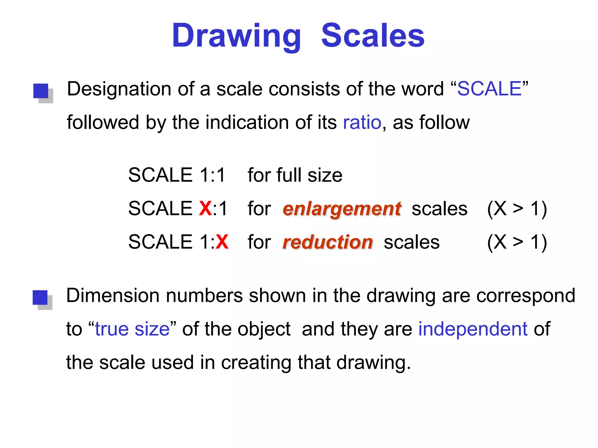
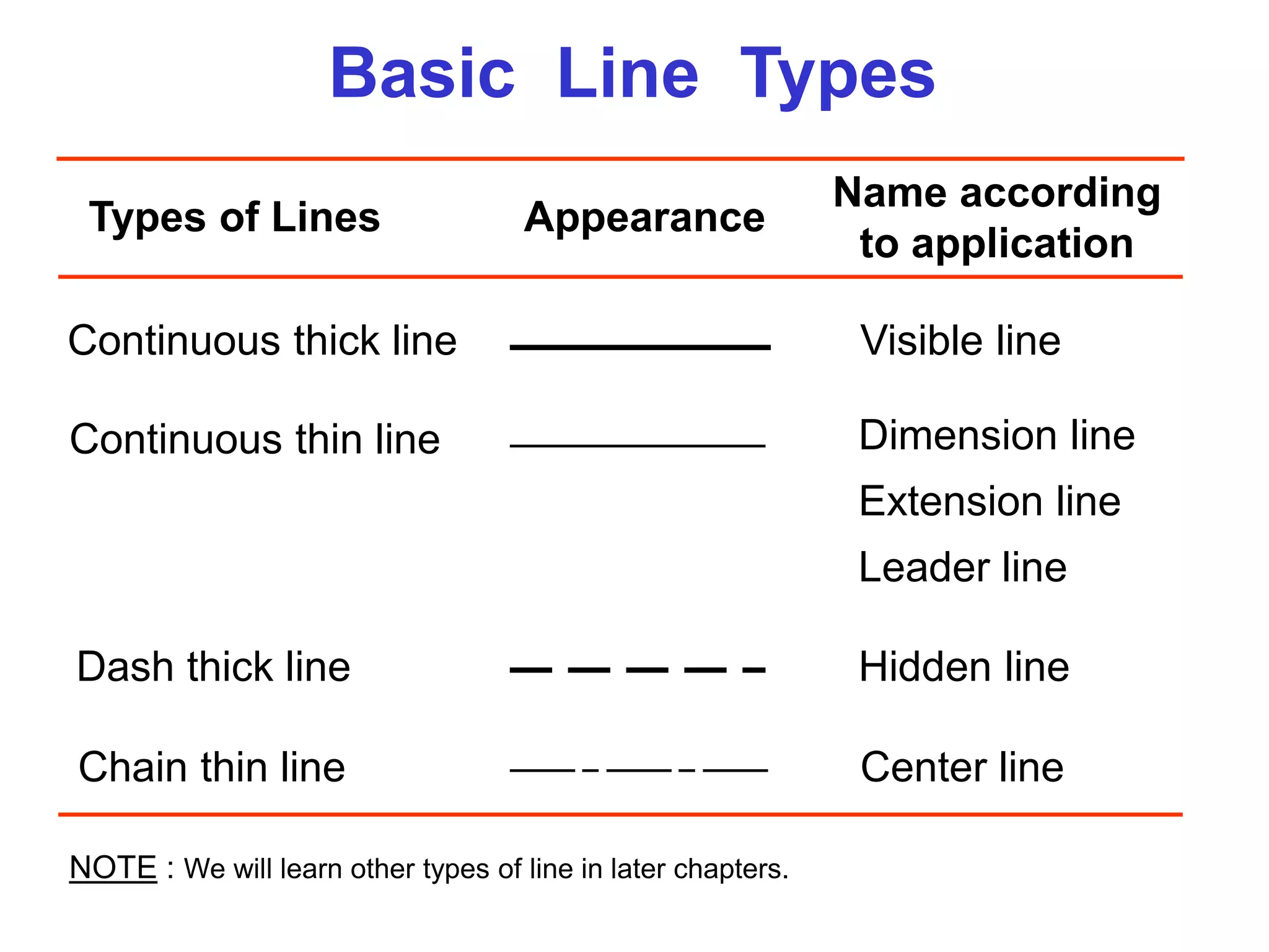
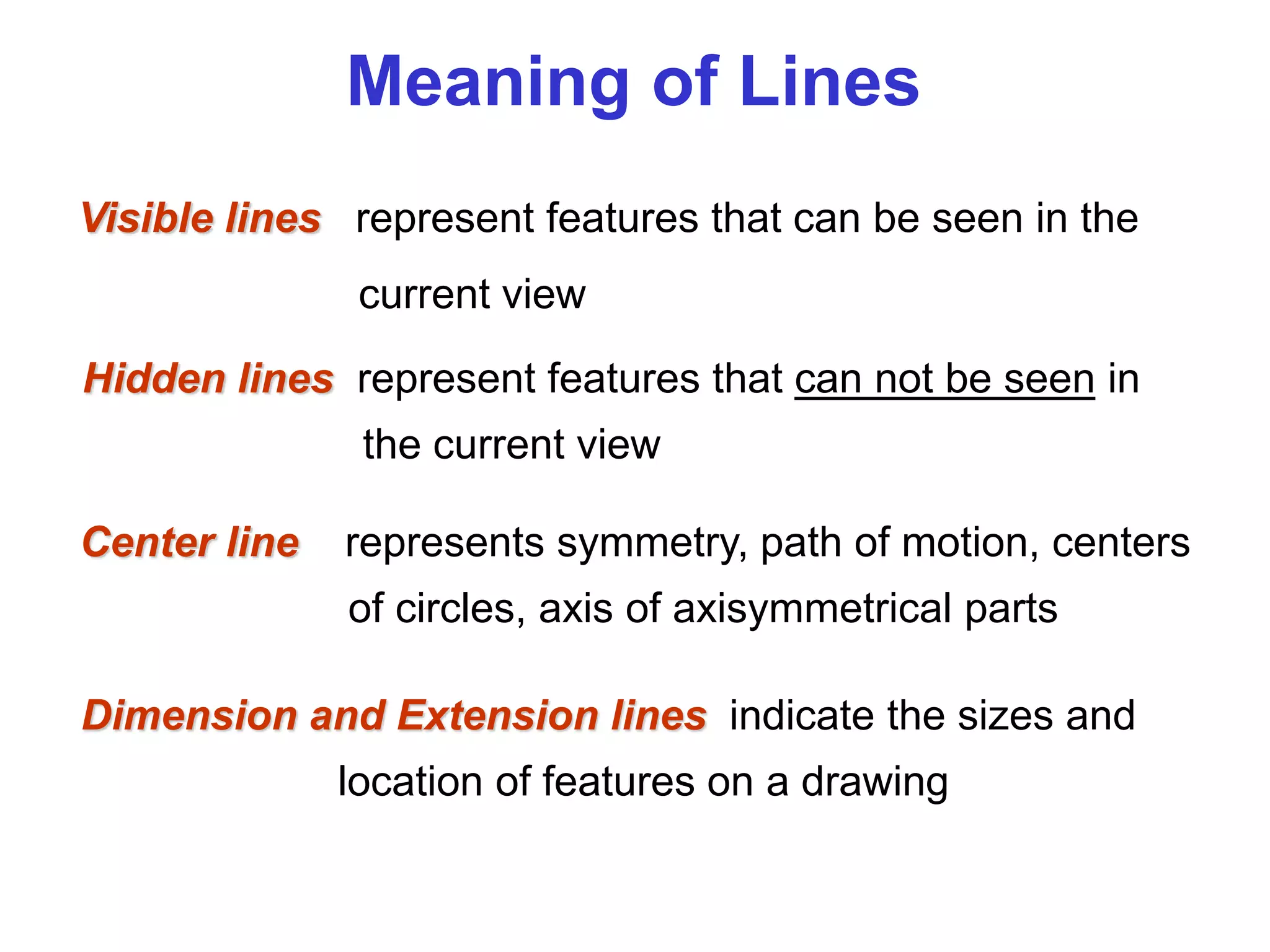
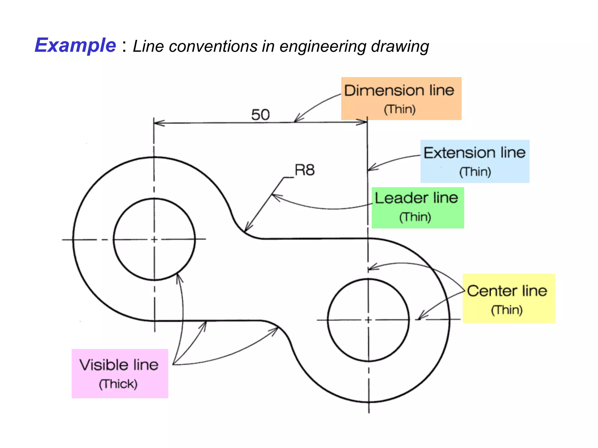
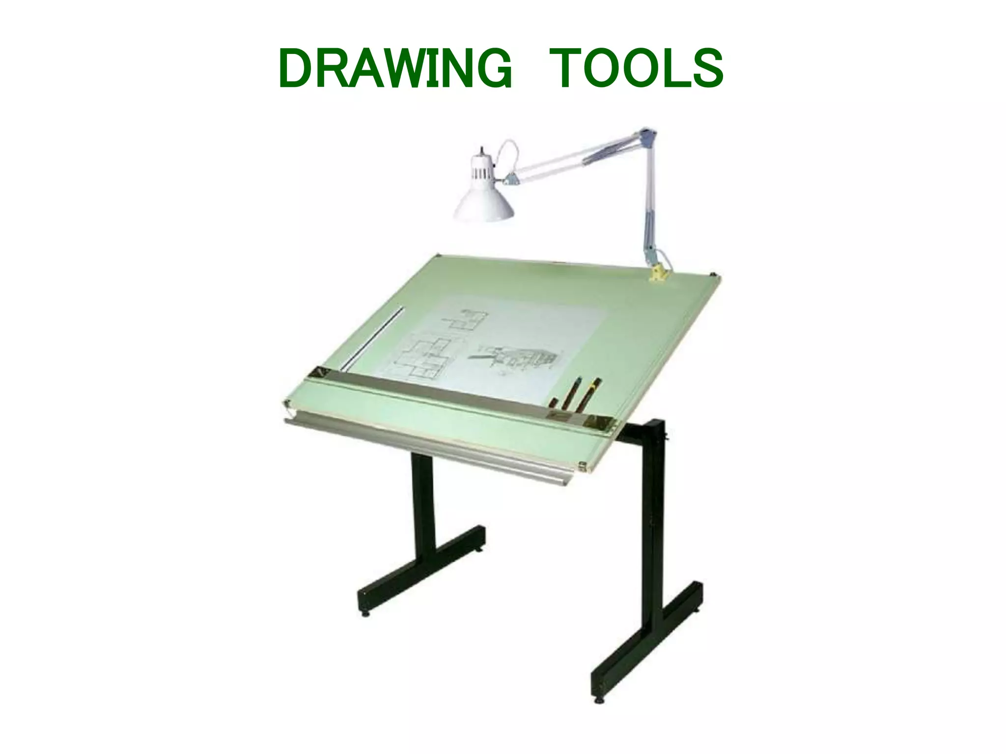
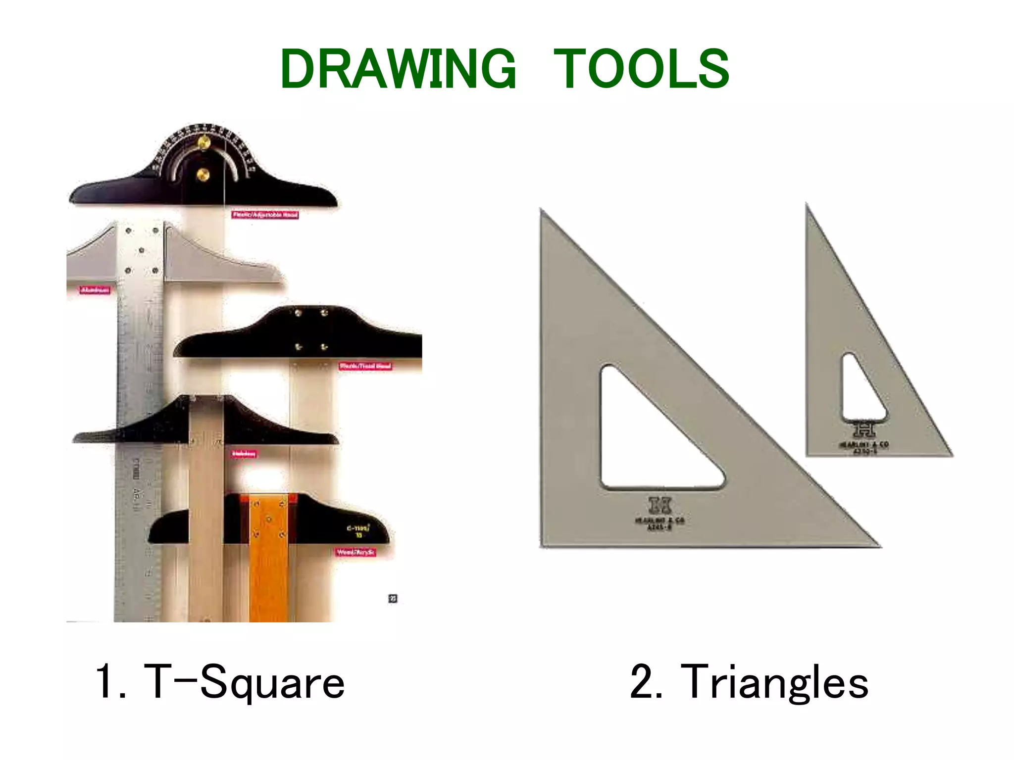
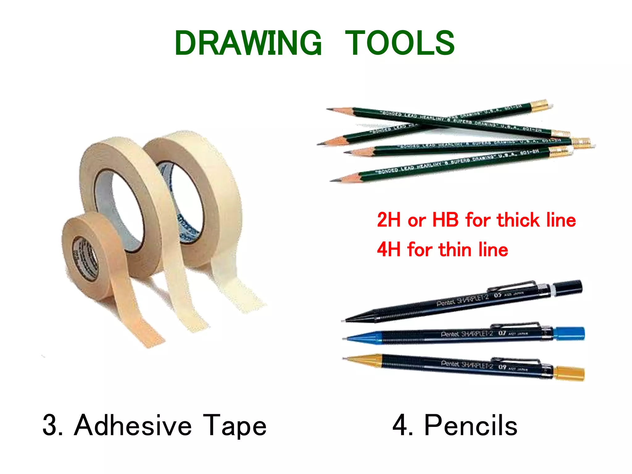
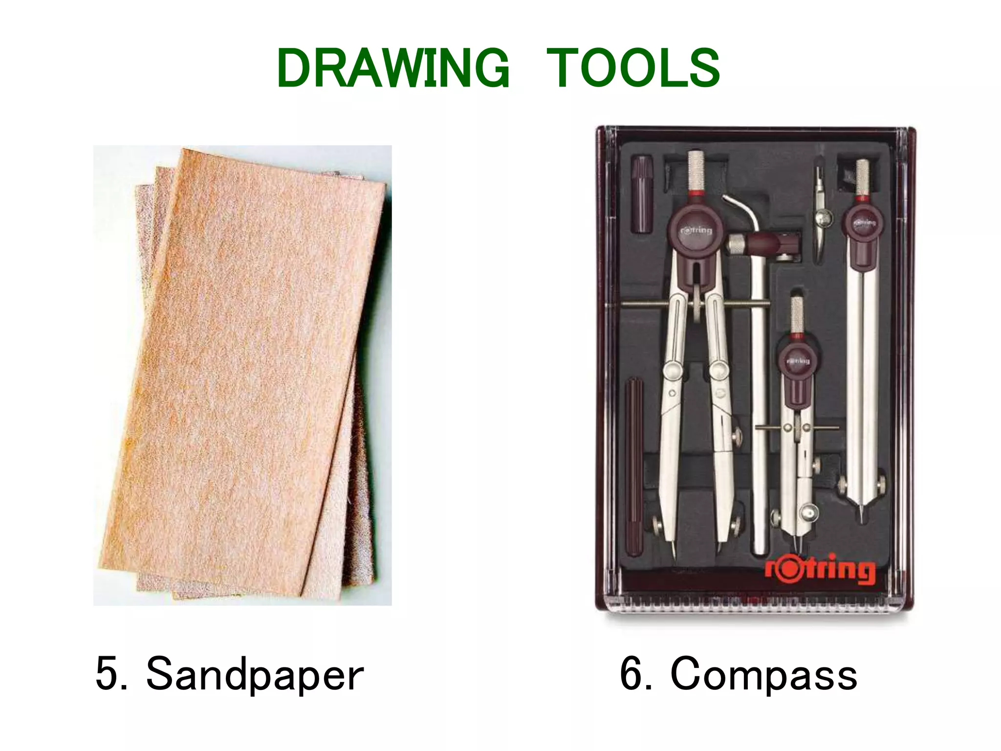
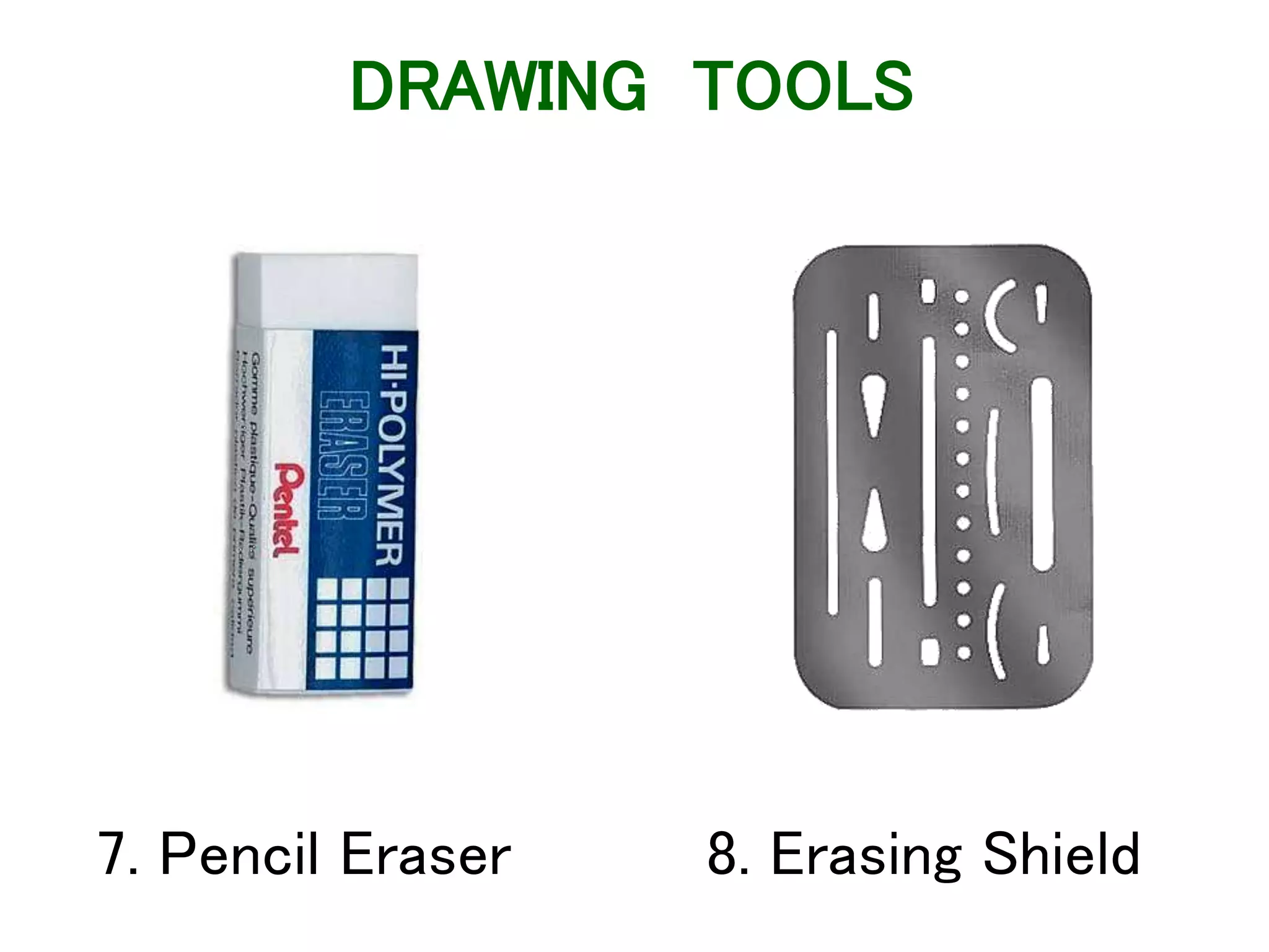
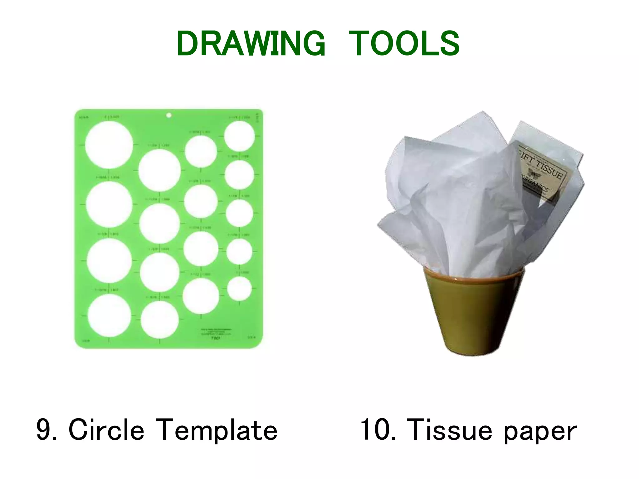

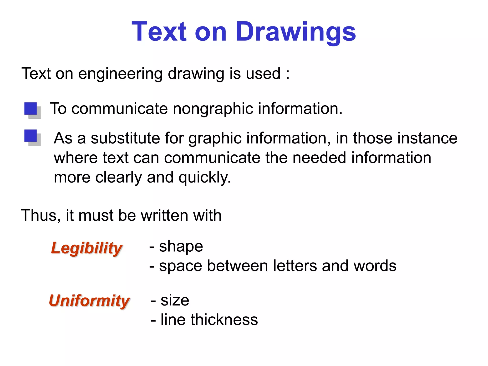
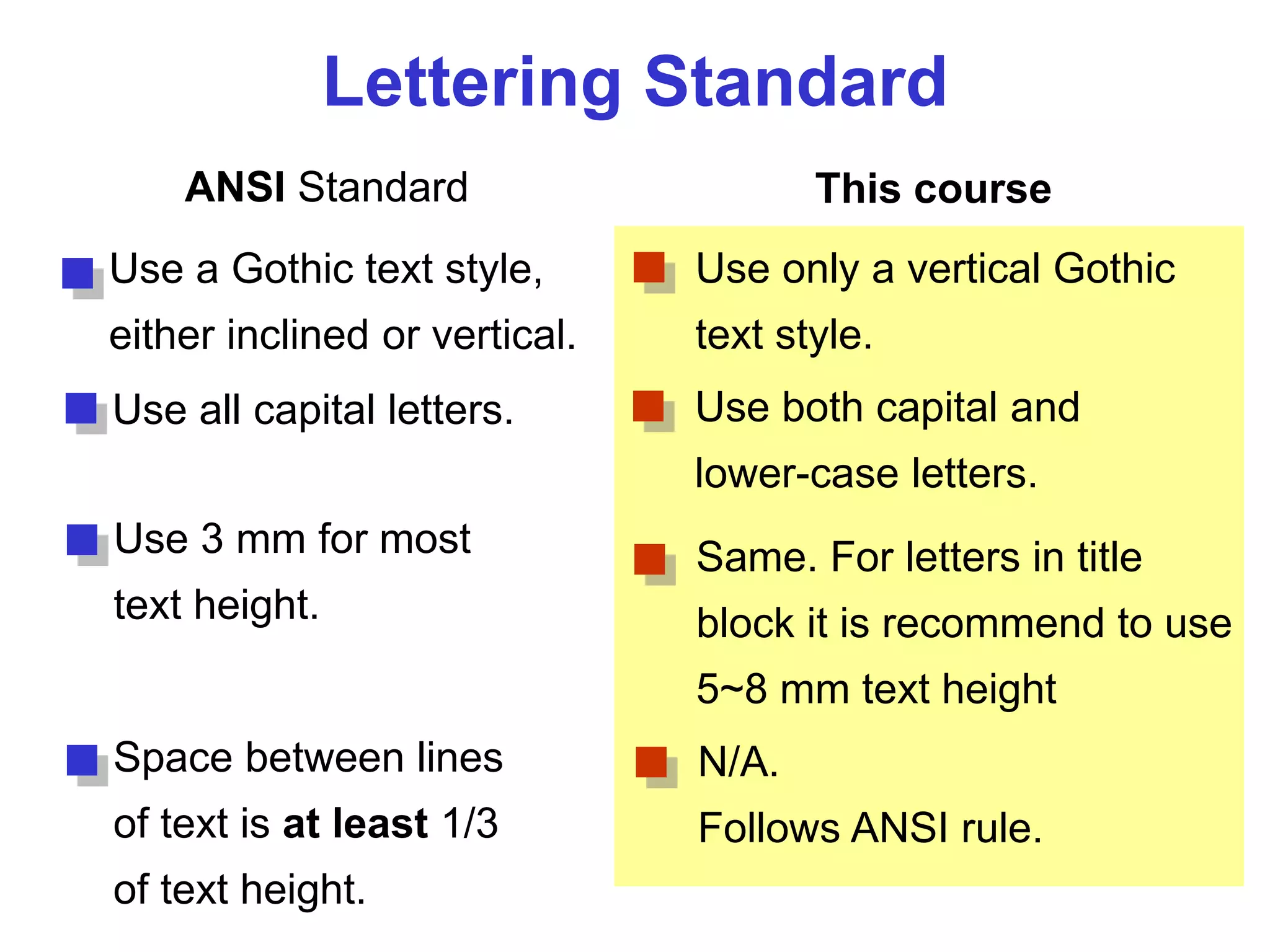
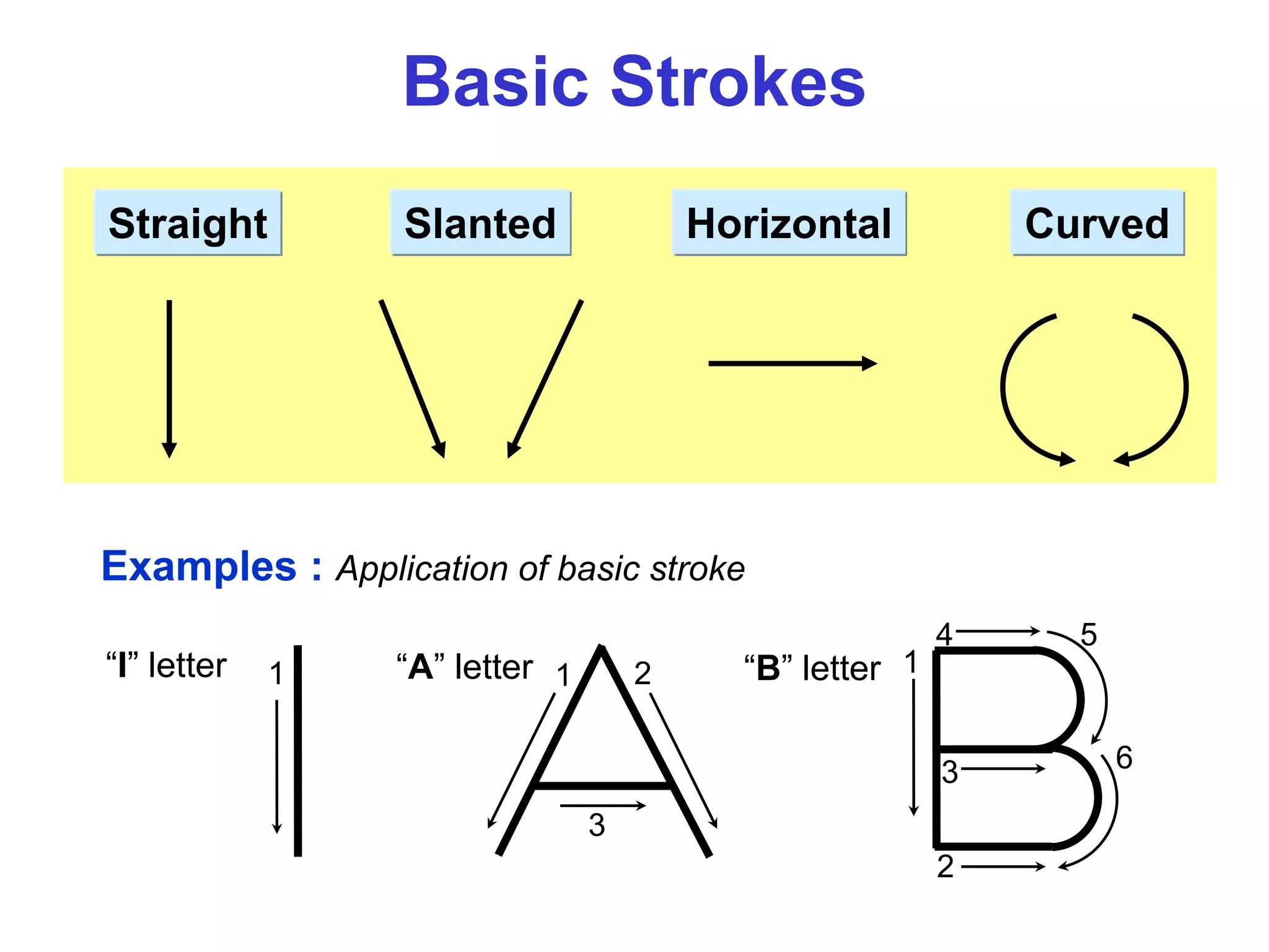
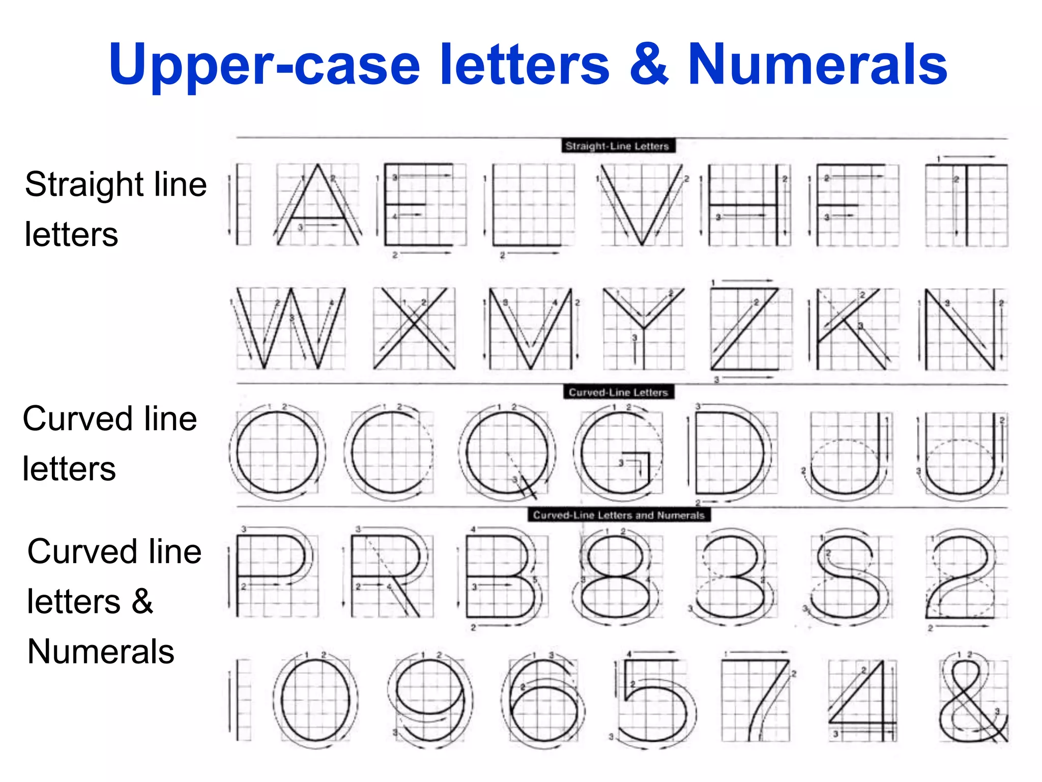
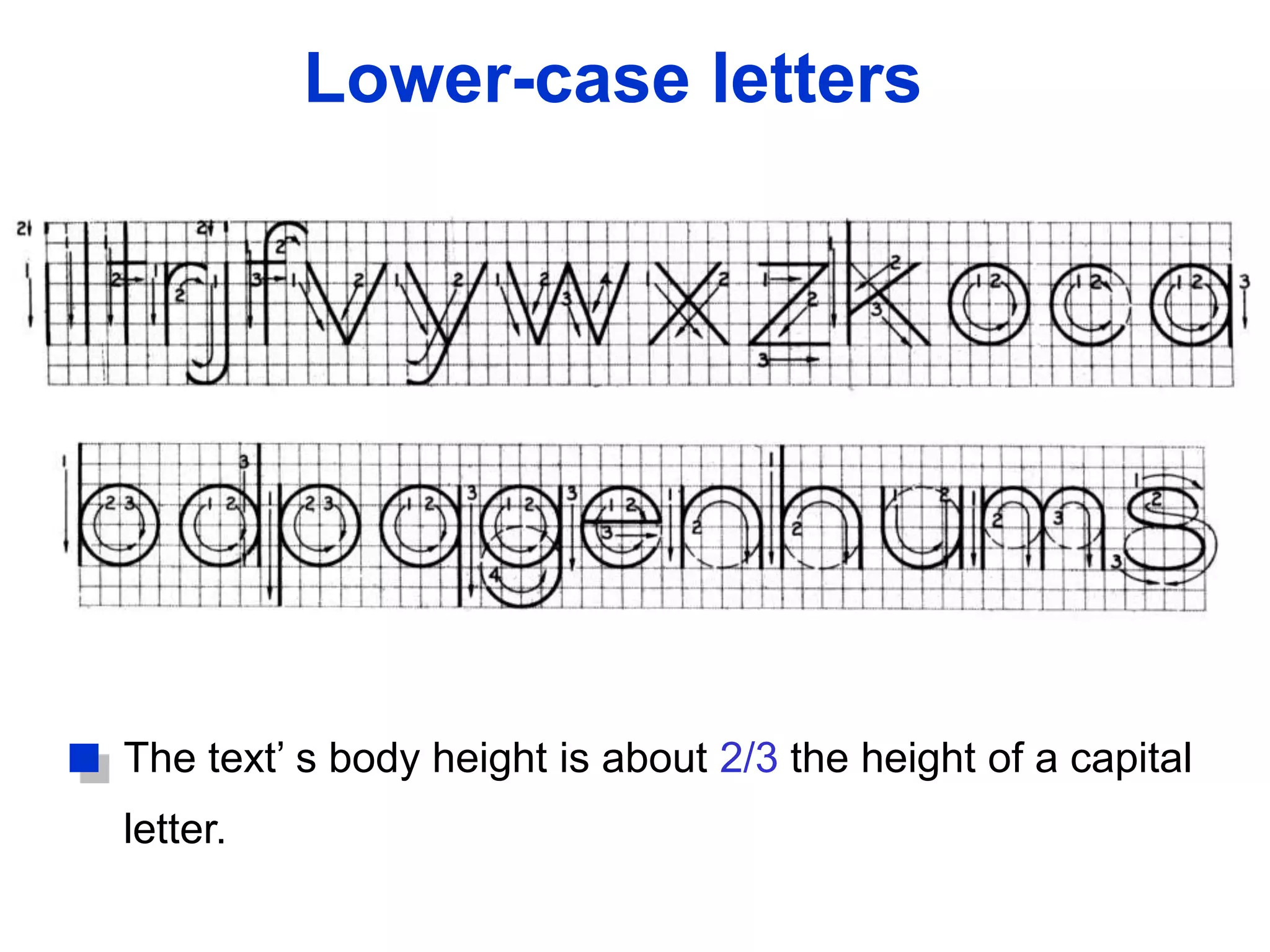
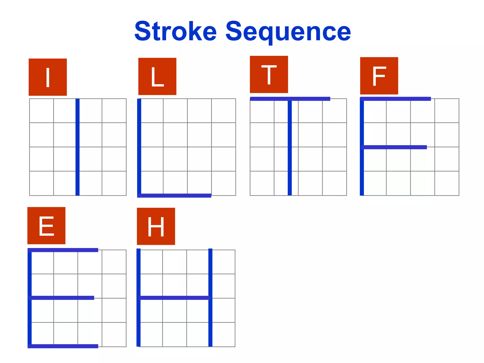
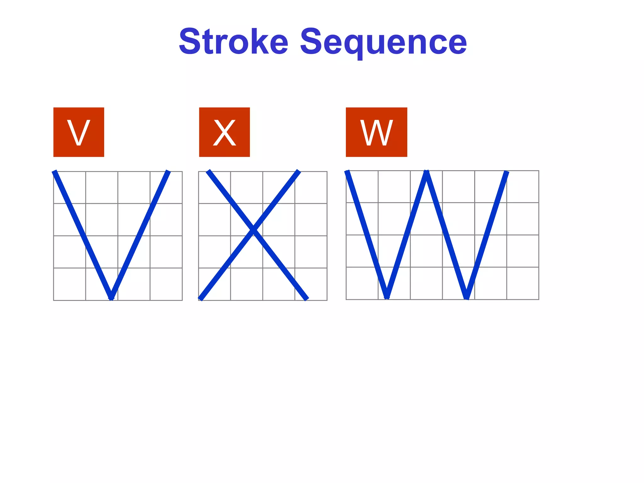
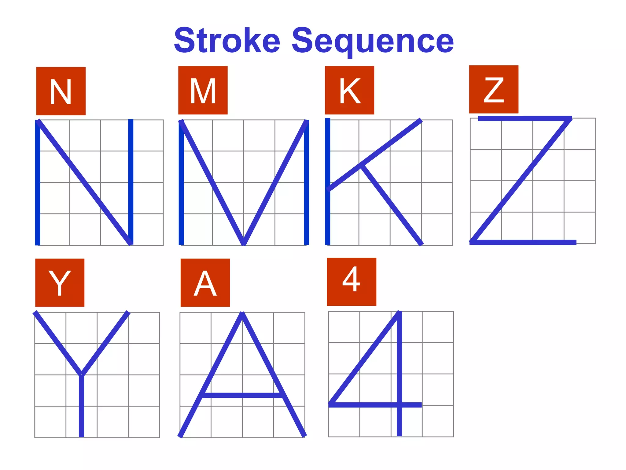
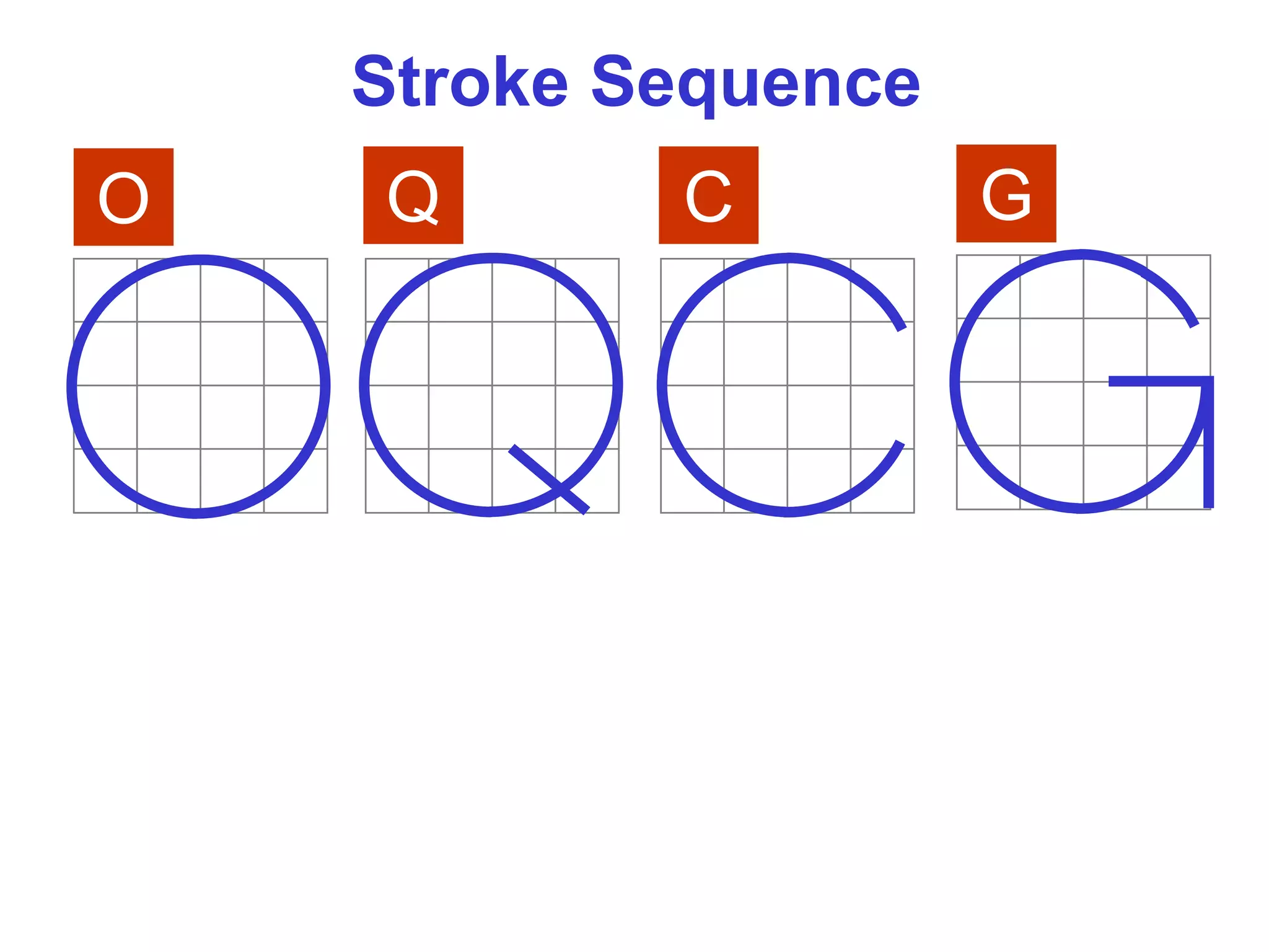
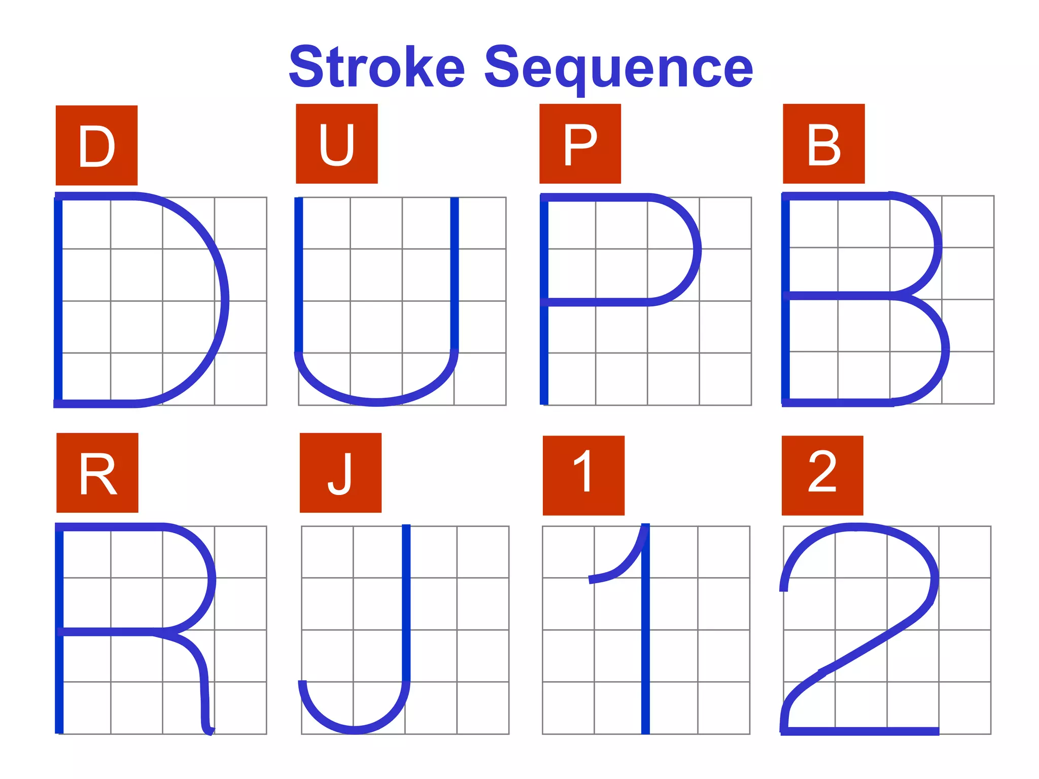
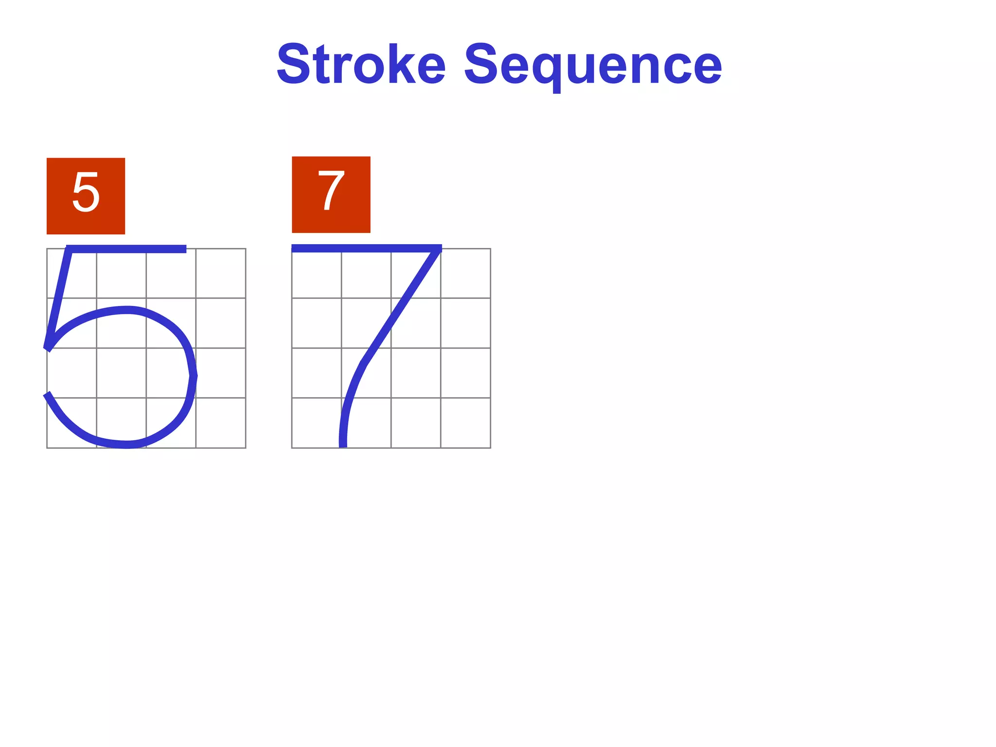

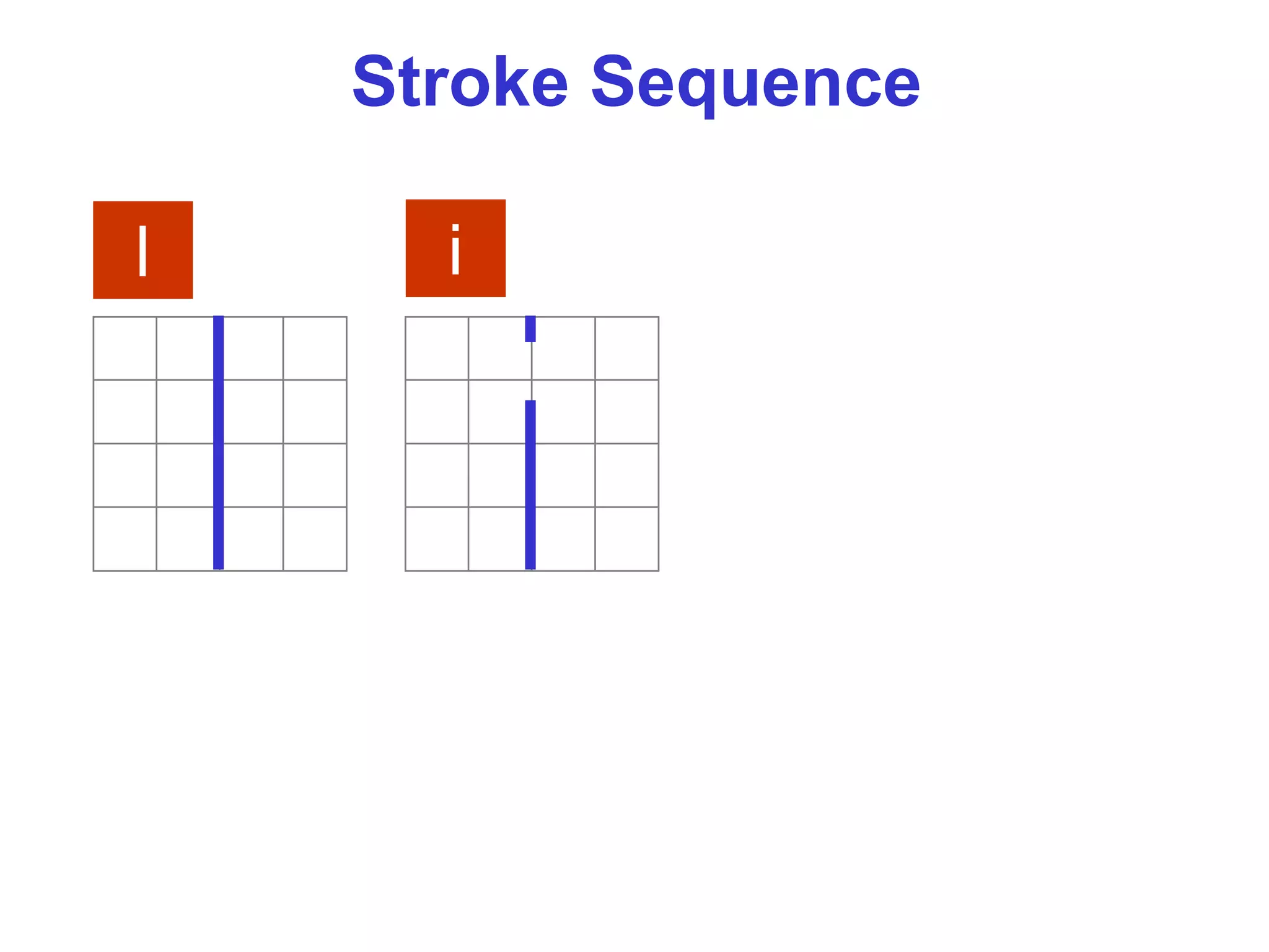
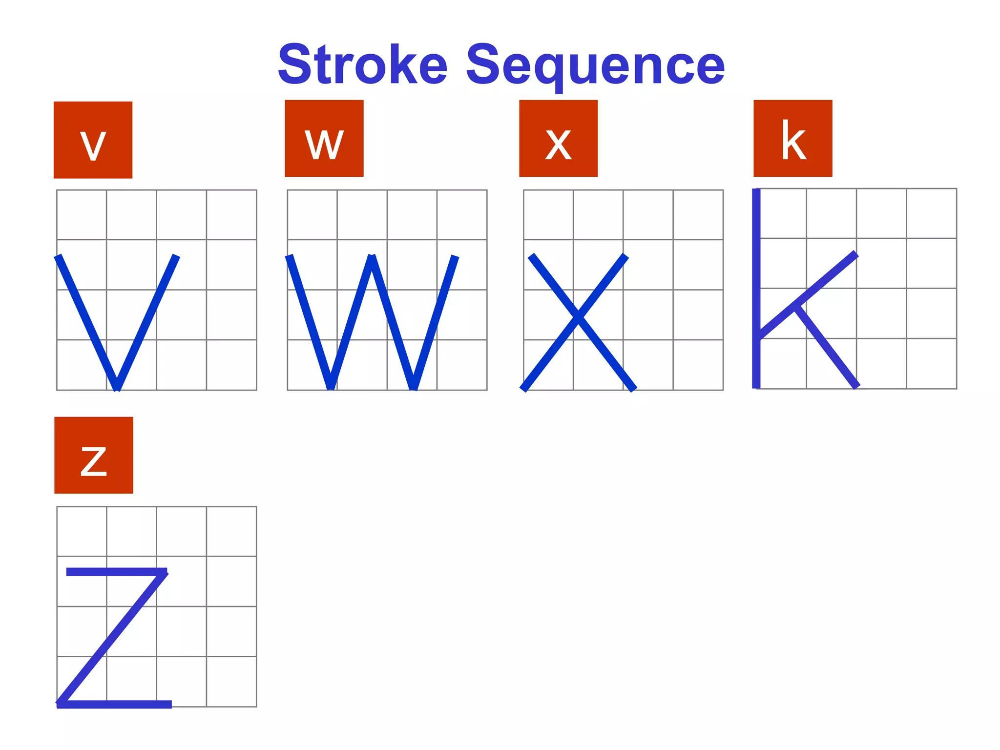
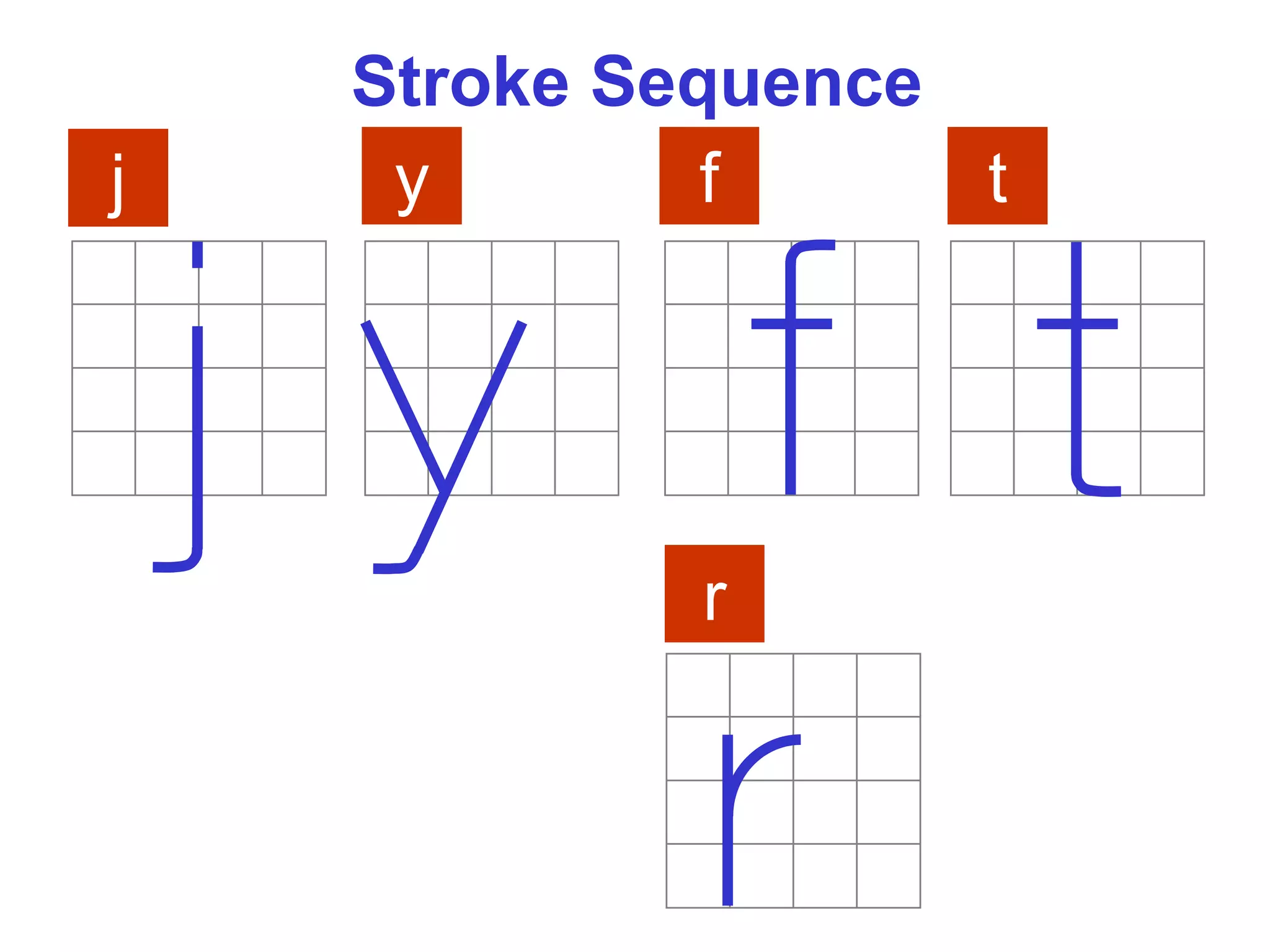
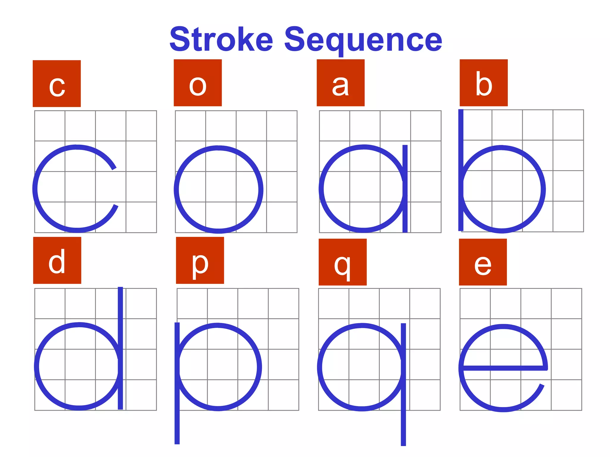
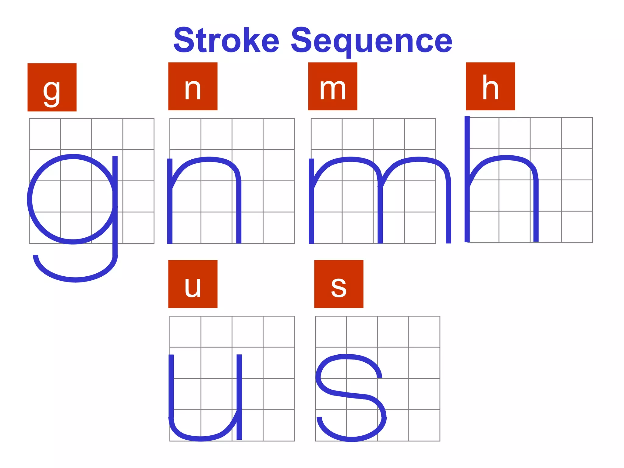
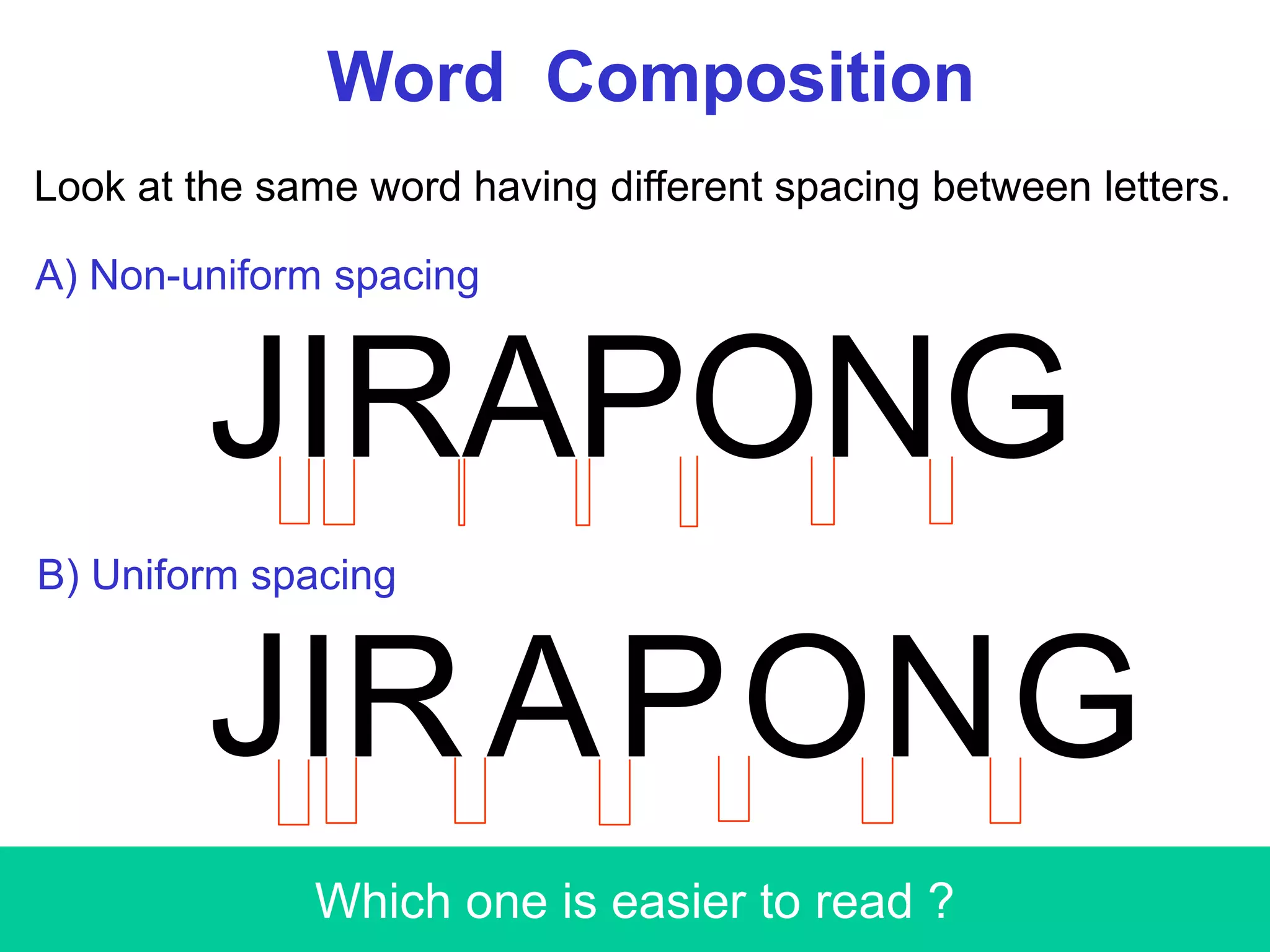
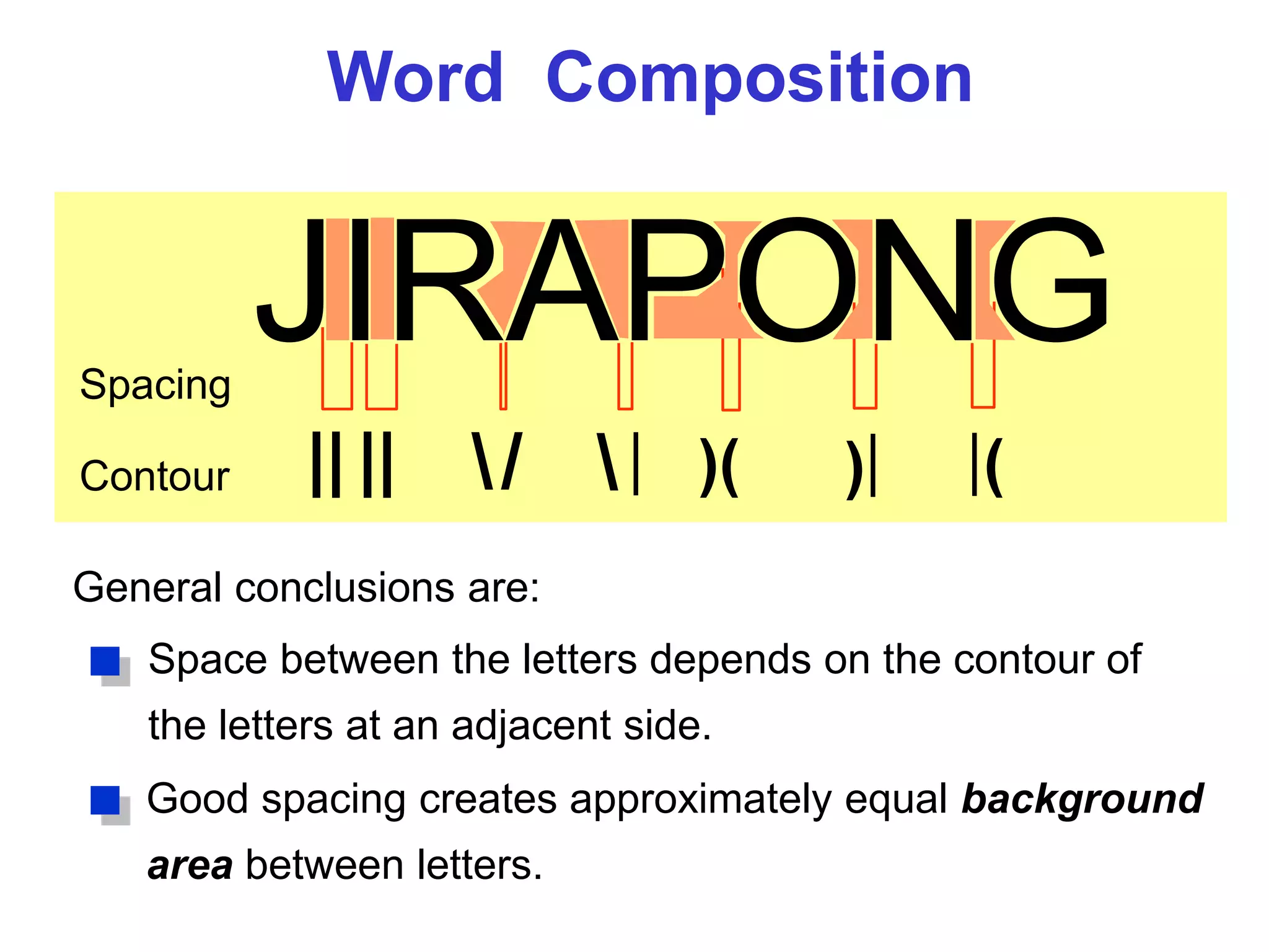

This chapter provides an overview of engineering drawings and their components. It discusses drawing standards, the graphics and word languages used to describe objects, and traditional drawing tools. It also covers topics like line types, lettering, scales, and layout of a drawing sheet. Engineering drawings combine graphics and text to precisely depict the size, shape, and specifications of objects in a standardized way to facilitate understanding between technical teams.


![W1-Introduction to ED [Autosaved].pptx](https://cdn.slidesharecdn.com/ss_thumbnails/w1-introductiontoedautosaved-221025152231-90341e07-thumbnail.jpg?width=640&height=640&fit=bounds)