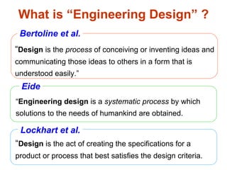
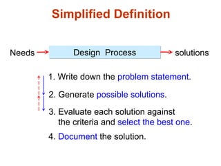
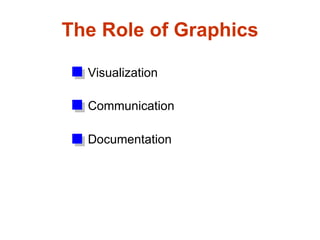
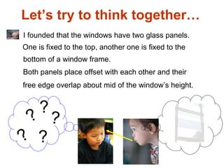
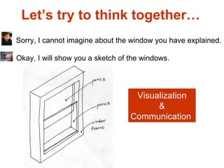
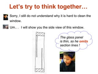
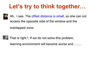
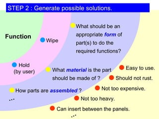
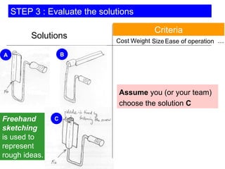
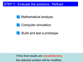
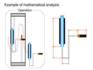
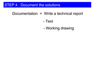
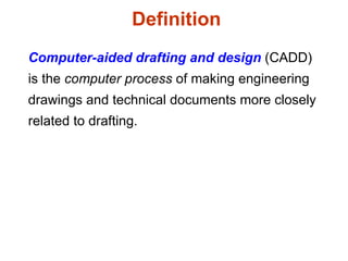
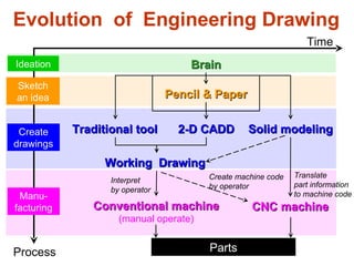
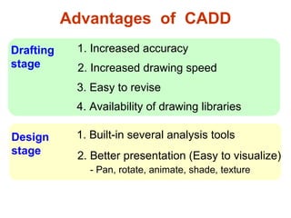
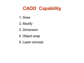
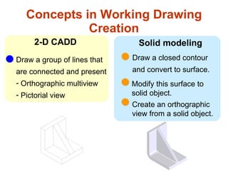
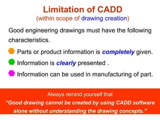
Basics of engineering drawing by Rishabh NatholiaRISHABH NATHOLIA
This is my work to make sure it is easy to understand the basic of Mechanical Engineer Drawing.It is a made for all and a quick bite to the very basics of engineering drawing. This data will also help the students to score more in their subjects. This will also help on design sector interviews.
this is an essential originally power point created notes in section view of engineering graphics and drawing hope you enjoy this and take its benefits....
Download link: https://www.researchgate.net/publication/318852873_Engineering_Drawing_-_I
DOI: 10.13140/RG.2.2.22512.56328
An engineering drawing is a type of technical drawing, used to fully and clearly define requirements for engineered items, and is usually created in accordance with standardized conventions for layout, nomenclature, interpretation, appearance size, etc.
Its purpose is to accurately and unambiguously capture all the geometric features of a product or a component. The end goal of an engineering drawing is to convey all the required information that will allow a manufacturer to produce that component.
CADmantra Technologies Pvt. Ltd. is one of the best Cad training company in northern zone in India . which are provided many types of courses in cad field i.e AUTOCAD,SOLIDWORK,CATIA,CRE-O,Uniraphics-NX, CNC, REVIT, STAAD.Pro. And many courses
Contact: www.cadmantra.com
www.cadmantra.blogspot.com
www.cadmantra.wix.com
Solid Modeling Assignment EGR 201-100 Spring 2018 .docxwhitneyleman54422
Solid Modeling Assignment
EGR 201-100
Spring 2018
Extra Credit Value: Equal to 2 homework assignments or in-class quizzes.
Due Date: March 19th by Midnight.
Assignment:
1) Using CAD (computer aided design) software, reproduce the four technical drawings.
2) Complete the survey.
3) Submit documents by email to [email protected]
Note: if you have access to Solidworks or another program and wish to use it instead, then produce the
four technical drawings and turn them in for full credit. You don’t have to use FreeCAD.
Note: the survey is part of the grade, so make sure you fill it out.
Table of Contents
Purpose of this Assignment .................................................................................................... 2
Background on Solid Modeling ............................................................................................... 2
Software Installation ............................................................................................................. 3
Assignment ........................................................................................................................... 4
Survey ................................................................................................................................... 8
Tutorial and Creating Part 1 ................................................................................................... 9
Step One - Base ............................................................................................................................ 10
Step Two – Top Notches ............................................................................................................... 14
Step Three - Extrusion .................................................................................................................. 17
Step Four – Center Hole ................................................................................................................ 18
Remove Duplicated Volumes ........................................................................................................ 20
Produce Technical Drawing ........................................................................................................... 20
Purpose of this Assignment
By drawing 3D models and producing technical drawings, you will learn to interpret x,y,z coordinates on
engineering drawings, such as those found in the Engineering Statics textbook.
Background on Solid Modeling
CAD software generally fit into one of two categories:
Solid modeling - modeling solid shapes (volumes). Materials are clearly defined.
Surface modeling - modeling wireframes and surfaces, which are hollow.
Solid modeling is clearly useful if we want to investigate stresses and strains in our designs. You
can draw solid volumes, assign material properties (wood, brick, steel, glass, aluminum), and then
subject them to loads. Generally, most.
To design is to plan or organize something for a specific use, or to create something to meet a specific need. Often, designs provide solutions to problem situations. Design solutions are created through the Design Process. This process will vary depending upon what is being designed
Software development is not one size fits all. Domain-Driven Design is significant where there's high complexity and high value. In these areas different tools might be needed. EventStorming is the best way I know to gather requirements in a complex environment, and also maps with CQRS/ES architecture perfectly.
An Inventor DWG file can be opened with relative ease in AutoCAD, as well as in DWG TrueView and other CAD programmes. This means that you can send your drawing to someone who does not have Inventor installed on their computer. Collaboration opportunities within your organisation and supply chain will be facilitated only by this action.
A Design Thinking Workshop for the MSIS CoreCarl M. Briggs Ph..docxblondellchancy
A Design Thinking Workshop for the MSIS Core
Carl M. Briggs Ph.D.
Fettig/Whirlpool Faculty Fellow
Co-Director, Business Operations Consulting Workshop
Fall 2019
1
Outline
Welcome & Introductions
What is Design Thinking?
About the class
Exercises:
Conditioning Exercise
Show Don’t Tell
Welcome & Introductions
Introductions…
Professor Carl M. Briggs Ph.D.
26 years of experience leading, and managing projects, and teaching the principles of effective project management to undergraduates, MBA’s and executives in the United States, Europe and Asia. Academic appointments in the United States (IU) , the Europe (Berlin) and Asia (Seoul).
Married to Annette Hill Briggs and father to Mariah, Ben and Emily.
Academia
Industries
Companies
Consulting
Mfg.
Healthcare Life Sciences
Supply Chain & Strategic Sourcing
Regions
NASA
Toyota
Samsung
FedEx
WalMart
Samsung
US DOD
4
Why we’re here…
?
?
?
What kind of problems have you solved?
6
MY STORY
YOUR WORLD…
MY WORLD…
What is Design Thinking?
BAD DESIGN MAY NOT BE IMMEDIATELY OBVIOUS
BUT OVER TIME THE TRUTH BEGINS TO SHOW
UNTIL IT IS ALL THAT IS LEFT, AND ALL
THAT YOUR CUSTOMERS REMEMBER
Bad design is all around us…
9
Design is not everything, but it somehow gets into everything.
Ralph Caplan, By Design
Design Thinking is …
… human-centered, collaborative, possibility-driven, options-focused, and iterative.
… the confidence that new, better things are possible and that you can make them happen.
Ralph Caplan, born January 4, 1925 is a design consultant, writer and public speaker. After serving in the Marines in WWII, he graduated from Earlham College and then went on to Indiana University for his Masters Degree. He later taught at Wabash College before moving to NYC where he became editor of Industrial Design.
He is the author of By Design: Why There are No Locks on the Bathroom Doors in the Hotel Louis XIV and Other Object Lessons.
He is considered a founding father of modern design thinking.
10
Roots of Design Thinking…
Developed/Made famous by Tim Brown at IDEO, taught at the Stanford School of Design.
Very influential in design circles, but becoming more influential in business
DEFINITION:
“A making-based problem solving process that is rooted in human empathy, done iteratively in collaborative multi-disciplinary teams.”
The Thought Leaders…
Tim Brown (IDEO)
https://www.youtube.com/watch?v=UAinLaT42xY
When did Design Thinking Become Small?
“Instead of starting with technology, the team started with people and culture…”
Design vs. Design Thinking
Design became small when it became the tool of consumerism
“Instead of starting with technology, the team started with people and culture…”
Design Thinking is about collaborative human creativity applied using a specific mindset and process framework focused on solving a wicked problem
Collaborative
Human
Creativity
Mindset
The Design Thin ...
Part C Developing Your Design SolutionThe Production Cycle.docxsmile790243
Part C Developing Your Design
Solution
The Production Cycle
Within the four stages of the design workflow there are two distinct parts.
The first three stages, as presented in Part B of this book, were described
as ‘The Hidden Thinking’ stages, as they are concerned with undertaking
the crucial behind-the-scenes preparatory work. You may have completed
them in terms of working through the book’s contents, but in visualisation
projects they will continue to command your attention, even if that is
reduced to a background concern.
You have now reached the second distinct part of the workflow which
involves developing your design solution. This stage follows a production
cycle, commencing with rationalising design ideas and moving through to
the development of a final solution.
The term cycle is appropriate to describe this stage as there are many loops
of iteration as you evolve rapidly between conceptual, practical and
technical thinking. The inevitability of this iterative cycle is, in large part,
again due to the nature of this pursuit being more about optimisation rather
than an expectation of achieving that elusive notion of perfection. Trade-
offs, compromises, and restrictions are omnipresent as you juggle ambition
and necessary pragmatism.
How you undertake this stage will differ considerably depending on the
nature of your task. The creation of a relatively simple, single chart to be
slotted into a report probably will not require the same rigour of a formal
production cycle that the development of a vast interactive visualisation to
be used by the public would demand. This is merely an outline of the most
you will need to do – you should edit, adapt and participate the steps to fit
with your context.
There are several discrete steps involved in this production cycle:
Conceiving ideas across the five layers of visualisation design.
Wireframing and storyboarding designs.
Developing prototypes or mock-up versions.
219
Testing.
Refining and completing.
Launching the solution.
Naturally, the specific approach for developing your design solution (from
prototyping through to launching) will vary hugely, depending particularly
on your skills and resources: it might be an Excel chart, or a Tableau
dashboard, an infographic created using Adobe Illustrator, or a web-based
interactive built with the D3.js library. As I have explained in the book’s
introduction, I’m not going to attempt to cover the myriad ways of
implementing a solution; that would be impossible to achieve as each task
and tool would require different instructions.
For the scope of this book, I am focusing on taking you through the first
two steps of this cycle – conceiving ideas and wireframing/storyboarding.
There are parallels here with the distinctions between architecture (design)
and engineering (execution) – I’m effectively chaperoning you through to
the conclusion of your design thinking.
To fulfil this, Part C presents a detailed breakdown of the many design
.
Similar to Engineering Drawing: Chapter 13 roles of engineering drawing (20)
How to Make a Field invisible in Odoo 17Celine George
It is possible to hide or invisible some fields in odoo. Commonly using “invisible” attribute in the field definition to invisible the fields. This slide will show how to make a field invisible in odoo 17.
We all have good and bad thoughts from time to time and situation to situation. We are bombarded daily with spiraling thoughts(both negative and positive) creating all-consuming feel , making us difficult to manage with associated suffering. Good thoughts are like our Mob Signal (Positive thought) amidst noise(negative thought) in the atmosphere. Negative thoughts like noise outweigh positive thoughts. These thoughts often create unwanted confusion, trouble, stress and frustration in our mind as well as chaos in our physical world. Negative thoughts are also known as “distorted thinking”.
The Indian economy is classified into different sectors to simplify the analysis and understanding of economic activities. For Class 10, it's essential to grasp the sectors of the Indian economy, understand their characteristics, and recognize their importance. This guide will provide detailed notes on the Sectors of the Indian Economy Class 10, using specific long-tail keywords to enhance comprehension.
For more information, visit-www.vavaclasses.com
Ethnobotany and Ethnopharmacology:
Ethnobotany in herbal drug evaluation,
Impact of Ethnobotany in traditional medicine,
New development in herbals,
Bio-prospecting tools for drug discovery,
Role of Ethnopharmacology in drug evaluation,
Reverse Pharmacology.
Palestine last event orientationfvgnh .pptxRaedMohamed3
An EFL lesson about the current events in Palestine. It is intended to be for intermediate students who wish to increase their listening skills through a short lesson in power point.
Instructions for Submissions thorugh G- Classroom.pptxJheel Barad
This presentation provides a briefing on how to upload submissions and documents in Google Classroom. It was prepared as part of an orientation for new Sainik School in-service teacher trainees. As a training officer, my goal is to ensure that you are comfortable and proficient with this essential tool for managing assignments and fostering student engagement.
Students, digital devices and success - Andreas Schleicher - 27 May 2024..pptxEduSkills OECD
Andreas Schleicher presents at the OECD webinar ‘Digital devices in schools: detrimental distraction or secret to success?’ on 27 May 2024. The presentation was based on findings from PISA 2022 results and the webinar helped launch the PISA in Focus ‘Managing screen time: How to protect and equip students against distraction’ https://www.oecd-ilibrary.org/education/managing-screen-time_7c225af4-en and the OECD Education Policy Perspective ‘Students, digital devices and success’ can be found here - https://oe.cd/il/5yV
4. What is “Engineering Design” ? “ Engineering design is a systematic process by which solutions to the needs of humankind are obtained. “ Design is the process of conceiving or inventing ideas and communicating those ideas to others in a form that is understood easily.” “ Design is the act of creating the specifications for a product or process that best satisfies the design criteria. Lockhart et al. Eide Bertoline et al.
5. Simplified Definition Needs solutions Design Process 1. Write down the problem statement . 2. Generate possible solutions . 3. Evaluate each solution against the criteria and select the best one . 4. Document the solution.
6. The Role of Graphics Visualization Communication Documentation
7. Let’s try to think together… Yesterday, I went to ME department to buy a textbook . I saw the window panels are very dirty.
8. Let’s try to think together… Maybe, a person responsible to this job is lazy. I don’t think so. I saw she worked diligently. ..…
9. Let’s try to think together… I asked her, why don’t you clean those windows ? What did she answer you ? She said it is impossible to clean those windows. So, what do you think ? I looked at the windows again, then I understood her answer. What are your findings ?
10. Let’s try to think together… ? ? ? ? ? I founded that the windows have two glass panels. One is fixed to the top, another one is fixed to the bottom of a window frame. Both panels place offset with each other and their free edge overlap about mid of the window’s height.
11. Let’s try to think together… Sorry, I cannot imagine about the window you have explained. Okay, I will show you a sketch of the windows. Visualization & Communication
12. Let’s try to think together… Sorry, I still do not understand why it is hard to clean the Um.. . The glass panel is thin, so he omits section lines ! I will show you the side view of this window. window.
13. Let’s try to think together… Ah.. I see. The offset distance is small , so she can not That is right !. If we do not solve this problem, access the opposite side of the window and the overlapped zone. learning environment will become worse and …….
14. STEP 1 : Write down a broad problem statement.
15. STEP 2 : Generate possible solutions. 1. Hire a cleaning service company. 5. Design a homemade cleaning device. 2. Buy a usable device. 3. Redesign the window construction. 6. ……………………… Individual Teamwork 4. Change the window to concrete wall.
16. Cost STEP 3 : Evaluate the solutions Availability Criteria Simplicity Aesthetic 1. Hire a cleaning service company. 5. Design a homemade cleaning device. 2. Buy a usable device. 3. Redesign the window construction. 6. ……………………… 4. Change the window to concrete wall. … Assume you (or your team) make a decision that “ Design a homemade cleaning device” is the best solution under listed criteria.
17. To design a device that can clean the opposite side of glass panel and overlapping area effectively. STEP 1 : Write down a specific problem statement.
18. STEP 2 : Generate possible solutions. 1. Modify from an existing solution. 2. Ad hoc solution. Solutions A, B … Use a freehand sketch to record the solutions Ideation Patent Book
19. Major functions of a device 1. Wash & Polish (the panel) 2. Wipe Would you like to combine both functions into a single device ? Yes No 1) Two devices: One for wash & polish another one for wipe . Single device. 2) Single device but has a changeable part . Assume you (or your team) choose this choice. STEP 2 : Generate possible solutions.
20. To design a wiping device that can wipe the opposite side of glass panel and overlapping area effectively. STEP 1 : Write down a specific problem statement.
21. Function … … STEP 2 : Generate possible solutions. What material is the part should be made of ? What should be an appropriate form of part(s) to do the required functions? How parts are assembled ? Not too heavy. Not too expensive. Can insert between the panels. Hold (by user) Wipe Should not rust. Easy to use.
22. Cost Weight … Size Solutions Freehand sketching is used to represent rough ideas. Ease of operation STEP 3 : Evaluate the solutions Criteria Assume you (or your team) choose the solution C A B C
23. STEP 3 : Evaluate the solutions : Refined If this final results are unsatisfactory , the selected solution will be modified. Mathematical analysis Computer simulation Build and test a prototype
27. Computer-aided drafting and design (CADD) is the computer process of making engineering drawings and technical documents more closely related to drafting. Definition
28. Sketch an idea Create drawings Manu- facturing Parts Traditional tool 2-D CADD Solid modeling CNC machine Translate part information to machine code Pencil & Paper Ideation Brain Conventional machine (manual operate) Time Process Working Drawing Interpret by operator Evolution of Engineering Drawing Create machine code by operator
29. Advantages of CADD 1. Increased accuracy 3. Easy to revise 2. Increased drawing speed 1. Built-in several analysis tools 2. Better presentation (Easy to visualize) - Pan, rotate, animate, shade, texture 4. Availability of drawing libraries Drafting stage Design stage
32. Limitation of CADD (within scope of drawing creation ) Good engineering drawings must have the following characteristics. Always remind yourself that “Good drawing cannot be created by using CADD software alone without understanding the drawing concepts.” Parts or product information is completely given. Information is clearly presented . Information can be used in manufacturing of part.
33.
34. Limitation of CADD (within scope of drawing interpretation ) Because they are frequently used technical document. Therefore, YOU MUST prepare yourself for interpreting (or visualizing) them when you become ENGINEER . No CADD software can create a pictorial view from an orthographic multiview.
35. Example : Necessary view selected by software. What do you think ? Good or Poor.
36. Example : Automatic dimension by software. What do you think ? Good or Poor.
37. What do you think ? Good or Poor. Example : Object with hole
38. What do you think ? Good or Poor Example : Autodimension of selected view.
39. Example : Object with hole What do you think ? Good or Poor