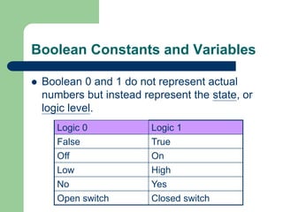
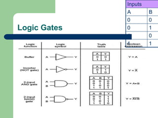
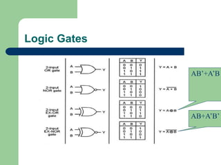
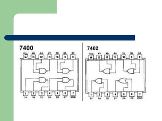
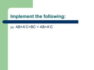
Digital Systems
Logic Gates and Boolean Algebra
Objectives
 Perform the three basic logic operations.
 Describe the operation of and construct the truth tables
for the AND, NAND, OR, and NOR gates, and the NOT
(INVERTER) circuit.
 Write the Boolean expression for the logic gates and
combinations of logic gates.
 Implement logic circuits using basic AND, OR, and
NOT gates.
Objectives
 Use either of the universal gates (NAND or NOR) to
implement a circuit represented by a Boolean
expression.
 Explain the advantages of constructing a logic-circuit
diagram using the alternate gate symbols versus the
standard logic-gate symbols.
 Describe the concept of active-LOW and active-HIGH
logic symbols.
Boolean Constants and Variables
 Boolean 0 and 1 do not represent actual
numbers but instead represent the state, or
logic level.
Logic 0 Logic 1
False True
Off On
Low High
No Yes
Open switch Closed switch
Three Basic Logic Operations
 OR
 AND
 NOT
Logic Gates
Inputs
A B
0 0
0 1
1 0
1 1
Logic Gates
AB’+A’B
AB+A’B’
 IN CASE OF NOT GATE OUTPUT IS NOT AS
INPUT.
 IN CASE OF AND GATE, OUTPUT WILL BE
ONE IF A AND B, ARE ONE
 IN THE CASE OF OR GATE, OUTPUT WILL
BE ONE IF A OR B IS ONE.
Truth Tables
 A truth table is a means for describing how a
logic circuit’s output depends on the logic
levels present at the circuit’s inputs.
Inputs Output
A B x
0 0 1
0 1 0
1 0 1
1 1 0
?
A
B
x
Logic Gates and there IC numbers
 AND – IC 7408
 OR – IC 7432
 NOT – IC 7404
 NOR – IC7402
 NAND – IC 7400
 XOR – IC 7486
IC Diagram’s
Poll Questions
Q1. What is the IC number of NAND gate?
a) 7408
b) 7402
c) 7400
d) 7404
Poll Question
Q2. If both the inputs of OR gate are high then
what will be the output?
a) 0
b) 1
c) Both a and b
d) None of these
Poll Question
Q3. The logic gate that will have HIGH or "1" at its output
when any one of its inputs is HIGH
a) NOR gate
b) AND gate
c) OR gate
d) NOT operation
Implement the following:
(a) AB+A’C+BC = AB+A’C
Example
Draw the circuit diagram to implement the
expression
)
)(
( C
B
B
A
x 


Logic gatesrevised.ppt

Logic gatesrevised.ppt

  • 1.
    Digital Systems Logic Gatesand Boolean Algebra
  • 2.
    Objectives  Perform thethree basic logic operations.  Describe the operation of and construct the truth tables for the AND, NAND, OR, and NOR gates, and the NOT (INVERTER) circuit.  Write the Boolean expression for the logic gates and combinations of logic gates.  Implement logic circuits using basic AND, OR, and NOT gates.
  • 3.
    Objectives  Use eitherof the universal gates (NAND or NOR) to implement a circuit represented by a Boolean expression.  Explain the advantages of constructing a logic-circuit diagram using the alternate gate symbols versus the standard logic-gate symbols.  Describe the concept of active-LOW and active-HIGH logic symbols.
  • 4.
    Boolean Constants andVariables  Boolean 0 and 1 do not represent actual numbers but instead represent the state, or logic level. Logic 0 Logic 1 False True Off On Low High No Yes Open switch Closed switch
  • 5.
    Three Basic LogicOperations  OR  AND  NOT
  • 6.
  • 7.
  • 8.
     IN CASEOF NOT GATE OUTPUT IS NOT AS INPUT.  IN CASE OF AND GATE, OUTPUT WILL BE ONE IF A AND B, ARE ONE  IN THE CASE OF OR GATE, OUTPUT WILL BE ONE IF A OR B IS ONE.
  • 9.
    Truth Tables  Atruth table is a means for describing how a logic circuit’s output depends on the logic levels present at the circuit’s inputs. Inputs Output A B x 0 0 1 0 1 0 1 0 1 1 1 0 ? A B x
  • 10.
    Logic Gates andthere IC numbers  AND – IC 7408  OR – IC 7432  NOT – IC 7404  NOR – IC7402  NAND – IC 7400  XOR – IC 7486
  • 11.
  • 13.
    Poll Questions Q1. Whatis the IC number of NAND gate? a) 7408 b) 7402 c) 7400 d) 7404
  • 14.
    Poll Question Q2. Ifboth the inputs of OR gate are high then what will be the output? a) 0 b) 1 c) Both a and b d) None of these
  • 15.
    Poll Question Q3. Thelogic gate that will have HIGH or "1" at its output when any one of its inputs is HIGH a) NOR gate b) AND gate c) OR gate d) NOT operation
  • 16.
    Implement the following: (a)AB+A’C+BC = AB+A’C
  • 17.
    Example Draw the circuitdiagram to implement the expression ) )( ( C B B A x   