Downloaded 287 times


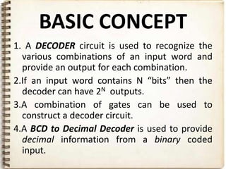
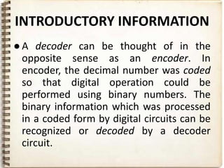
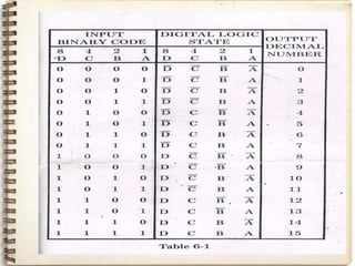
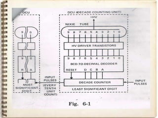

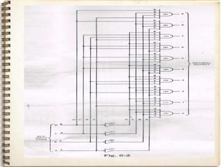
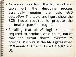
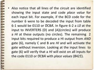
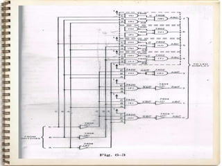
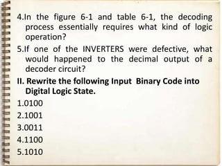
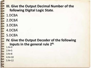
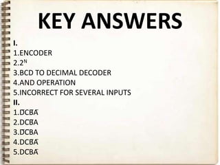


This document discusses decoders and provides details about binary coded decimal (BCD) to decimal decoders. It explains that decoders recognize various input combinations and provide corresponding outputs. A BCD to decimal decoder specifically provides decimal outputs from a binary coded input. The document then presents the circuit design and operation of a BCD to decimal decoder using AND gates. It analyzes how the circuit decodes input codes to activate the proper decimal output and discusses how faults could be identified by analyzing input-output relationships.