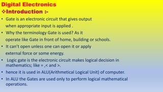
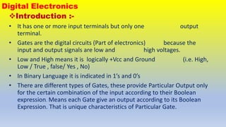
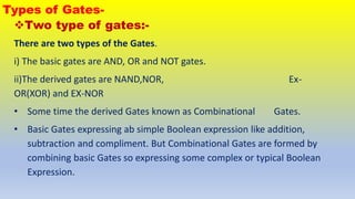
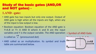
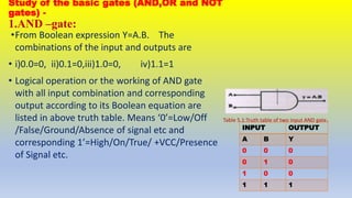
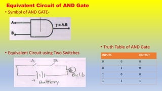
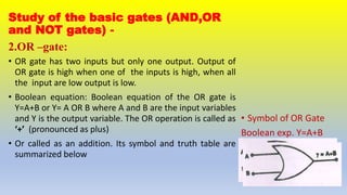
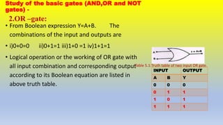
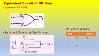
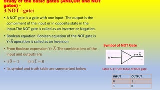
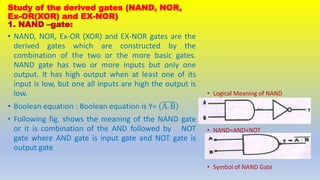
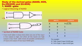
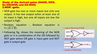
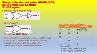
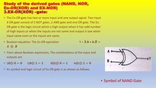
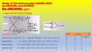
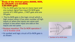
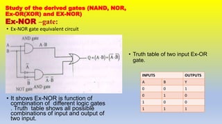
Department of Physics
B.SC.III
Sem-V.Paper-XII
DSE-E4- Digital and Analog Circuits and Instrumentation
Topic-Digital Electronics-Review of
basic logic gates.
Digital Electronics
Introduction :-
• Gate is an electronic circuit that gives output
when appropriate input is applied .
• Why the terminology Gate is used? As it
operate like Gate in front of home, building or schools.
• It can’t open unless one can open it or apply
external force or some energy.
• Logic gate is the electronic circuit makes logical decision in
mathematics; like = ,< and >.
• hence it is used in ALU(Arithmetical Logical Unit) of computer.
• In ALU the Gates are used only to perform logical mathematical
operations.
Digital Electronics
Introduction :-
• It has one or more input terminals but only one output
terminal.
• Gates are the digital circuits (Part of electronics) because the
input and output signals are low and high voltages.
• Low and High means it is logically +Vcc and Ground (i.e. High,
Low / True , false/ Yes , No)
• In Binary Language it is indicated in 1’s and 0’s
• There are different types of Gates, these provide Particular Output only
for the certain combination of the input according to their Boolean
expression. Means each Gate give an output according to its Boolean
Expression. That is unique characteristics of Particular Gate.
Types of Gates-
Two type of gates:-
There are two types of the Gates.
i) The basic gates are AND, OR and NOT gates.
ii)The derived gates are NAND,NOR, Ex-
OR(XOR) and EX-NOR
• Some time the derived Gates known as Combinational Gates.
• Basic Gates expressing ab simple Boolean expression like addition,
subtraction and compliment. But Combinational Gates are formed by
combining basic Gates so expressing some complex or typical Boolean
Expression.
Study of the basic gates (AND,OR
and NOT gates) -
1.AND –gate:
• AND gate has two inputs but only one output. Output of
AND gate is high when all the inputs are high, when any
of the input is low output is low.
• Boolean equation: Boolean equation of the AND gate is
Y=A.B or Y= A AND B where A and B are the input
variables and Y is the output variable. The AND operation
is called as ‘.’ (pronounced dot)
• AND called as an multiplication. Its symbol and truth
table are summarized below.
• Symbol of AND Gate
Boolean exp. Y=A.B
Study of the basic gates (AND,OR and NOT
gates) -
1.AND –gate:
•From Boolean expression Y=A.B. The
combinations of the input and outputs are
• i)0.0=0, ii)0.1=0,iii)1.0=0, iv)1.1=1
• Logical operation or the working of AND gate
with all input combination and corresponding
output according to its Boolean equation are
listed in above truth table. Means ‘0’=Low/Off
/False/Ground/Absence of signal etc and
corresponding 1’=High/On/True/ +VCC/Presence
of Signal etc.
Table 5.1:Truth table of two input AND gate.
INPUT OUTPUT
A B Y
0 0 0
0 1 0
1 0 0
1 1 1
Equivalent Circuit of AND Gate
• Symbol of AND GATE-
• Equivalent Circuit using Two Switches
• Truth Table of AND Gate
INPUTS OUTPUT
0 0 0
0 1 0
1 0 0
1 1 1
Study of the basic gates (AND,OR
and NOT gates) -
2.OR –gate:
• OR gate has two inputs but only one output. Output of
OR gate is high when one of the inputs is high, when all
the input are low output is low.
• Boolean equation: Boolean equation of the OR gate is
Y=A+B or Y= A OR B where A and B are the input variables
and Y is the output variable. The OR operation is called as
‘+’ (pronounced as plus)
• Or called as an addition. Its symbol and truth table are
summarized below
• Symbol of OR Gate
Boolean exp. Y=A+B
Study of the basic gates (AND,OR and NOT
gates) -
2.OR –gate:
• From Boolean expression Y=A+B. The
combinations of the input and outputs are
• i)0+0=0 ii)0+1=1 iii)1+0 =1 iv)1+1=1
• Logical operation or the working of OR gate with
all input combination and corresponding output
according to its Boolean equation are listed in
above truth table.
Table 5.1:Truth table of two input OR gate.
INPUT OUTPUT
A B Y
0 0 0
0 1 1
1 0 1
1 1 1
Equivalent Circuit of OR Gate
• Symbol of OR GATE-
• Equivalent Circuit using Two Switches
• Truth Table of OR Gate
INPUTS OUTPUT
0 0 0
0 1 1
1 0 1
1 1 1
Study of the basic gates (AND,OR and NOT
gates) -
3.NOT –gate:
• A NOT gate is a gate with one input. The output is the
compliment of the input or in opposite state in the
input.The NOT gate is called as an Inverter or Negation.
• Boolean equation: Boolean equation of the NOT gate is
Y=A operation is called as an Inversion
• From Boolean expression Y= A .The combinations of the
input and outputs are
• i) 0 = 1 ii) i) 1 = 0
• Its symbol and truth table are summarized below
Symbol of NOT Gate
Table 5.1:Truth table of NOT gate.
INPUT OUTPUT
0 1
1 0
Study of the derived gates (NAND, NOR,
Ex-OR(XOR) and EX-NOR)
1. NAND –gate:
• NAND, NOR, Ex-OR (XOR) and EX-NOR gates are the
derived gates which are constructed by the
combination of the two or the more basic gates.
NAND gate has two or more inputs but only one
output. It has high output when at least one of its
input is low, but one all inputs are high the output is
low.
• Boolean equation : Boolean equation is Y= A. B
• Following fig. shows the meaning of the NAND gate
or it is combination of the AND followed by NOT
gate where AND gate is input gate and NOT gate is
output gate
• Logical Meaning of NAND
• NAND=AND+NOT
• Symbol of NAND Gate
Study of the derived gates (NAND, NOR,
Ex-OR(XOR) and EX-NOR)
1. NAND –gate:
• Logical Meaning of NAND
• NAND=AND+NOT
• Symbol of NAND Gate
• From truth table it shows that when any one of the input
is low output is high, but when all the inputs are high
output is low. Truth table shows all possible combinations
of input and output of two input NAND gate.
For example :
IC-7400- Quad-2-input NAND gate
IC-7410-Triple 3- input NAND gate
INPUTS OUTPUTS
A B Y= A. B
0 0 1
0 1 1
1 0 1
1 1 0
Study of the derived gates (NAND, NOR,
Ex-OR(XOR) and EX-NOR)
2.NOR –gate:
• NOR gate has two or more inputs but only one
output. It has low output when at least one of
its input is high, but one all inputs are low the
output is high.
• Boolean equation : Boolean equation is
Y= A + B
• Following fig. shows the meaning of the NOR
gate or it is combination of the OR followed by
NOT gate where OR gate is input gate and NOT
gate is output gate
• Logical Meaning of NOR
• NOR=OR+NOT
• Symbol of NOR Gate
Study of the derived gates (NAND, NOR,
Ex-OR(XOR) and EX-NOR)
2. NOR –gate:
• Logical Meaning of NOR-
• NOR=OR+NOT
• Symbol of NOR Gate
• From truth table it shows that when any one of the input
is high output is low, but when all the inputs are low
output is high. Truth table shows all possible
combinations of input and output of two input For example :
IC-7402- Quad- 2-input NOR gate
IC-7427-Triple 3- input NOR gate
INPUTS OUTPUTS
A B Y= A + B
0 0 1
0 1 0
1 0 0
1 1 0
Truth table are summarized below
Study of the derived gates (NAND, NOR,
Ex-OR(XOR) and EX-NOR)
3.EX-OR(XOR) –gate:
• The Ex-OR gate has two or more input and one output signal. Two input
X-OR gate consist of 2 NOT gates ,2 AND gate and one OR gate. The Ex-
OR gate is the logic circuit which a high output when it has odd number
of high inputs or when the inputs are not same and output is low when
input same even or the inputs are same.
• Boolean equation: The Ex-OR operation Y = 𝑨.B + A.𝑩 =
𝑨 ⊕ 𝑩
• From above Boolean expression, The combinations of the input and
outputs are
• i)0⊕ 𝟎 = 𝟎 ii)0⊕ 𝟏 = 𝟏 iii)1⊕ 𝟎 = 𝟏 iv)1⊕ 𝟏 = 𝟎
• Its symbol and logic circuit of Ex-OR gate is as shown as fallows.
• Symbol of NAND Gate
Study of the derived gates (NAND, NOR,
Ex-OR(XOR) and EX-NOR)
Ex-OR(XOR)–gate:
• Logical circuit of the X-OR gate
Symbol of XOR
Proof:-i) 𝐿𝑒𝑡 𝐴 = 0, 𝐵 = 0. ∴ 𝑌 = 𝐴.B+A.𝐵 = 0.0+0.0 = 1.0 + 0.1 = 0 + 0 = 0
ii)Let A=0, B=1 .∴ 𝑌 = 𝐴. 𝐵 + 𝐴. 𝐵 = 0. 1 + 0. 1 = 1.1 + 0.0 = 1 + 0 = 1
iii)Let A=1,B=0 ∴ 𝑌 = 𝐴. 𝐵 + 𝐴. 𝐵 = 1. 0 + 1. 0 = 0.0 + 1.1 = 0 + 1 = 1
iv)Let A=1, B=1 ∴ 𝑌 = 𝐴. 𝐵 + 𝐴. 𝐵 = 1. 1 + 1. 1 = 0.1 + 1.0 = 0 + 0 = 0
INPUTS OUTPUTS
A B Y= 𝐴 ⊕ 𝐵
0 0 0
0 1 1
1 0 1
1 1 0
Study of the derived gates (NAND, NOR,
Ex-OR(XOR) and EX-NOR)
3.EX-NOR–gate:
• Symbol of Ex-NOR Gate
• The Ex-NOR gate has two or more input and
one output signal.Two input EX-NOR gate
consist of 2 AND gates , 2 NOT gate and one
OR gate.
• The Ex-NOR gate is the logic circuit which a
high output when it has even number of high
inputs or when the inputs are same and
output is low when input are odd or the
inputs are not same
• Boolean equation :The Ex-NOR operation Y
= 𝑨 ⊕ 𝑩 =(A.B) + (𝑨. 𝑩)
• Its symbol and logic circuit of Ex-NOR gate is
as shown.
Study of the derived gates (NAND, NOR,
Ex-OR(XOR) and EX-NOR)
Ex-NOR –gate:
• Ex-NOR gate equivalent circuit
• It shows Ex-NOR is function of
combination of different logic gates
. Truth table shows all possible
combinations of input and output of
two input.
• Truth table of two input Ex-OR
gate.
INPUTS OUTPUTS
A B Y
0 0 1
0 1 0
1 0 0
1 1 1

Digital Electronics-Review of Logic Gates.pptx

  • 2.
    Department of Physics B.SC.III Sem-V.Paper-XII DSE-E4-Digital and Analog Circuits and Instrumentation Topic-Digital Electronics-Review of basic logic gates.
  • 3.
    Digital Electronics Introduction :- •Gate is an electronic circuit that gives output when appropriate input is applied . • Why the terminology Gate is used? As it operate like Gate in front of home, building or schools. • It can’t open unless one can open it or apply external force or some energy. • Logic gate is the electronic circuit makes logical decision in mathematics; like = ,< and >. • hence it is used in ALU(Arithmetical Logical Unit) of computer. • In ALU the Gates are used only to perform logical mathematical operations.
  • 4.
    Digital Electronics Introduction :- •It has one or more input terminals but only one output terminal. • Gates are the digital circuits (Part of electronics) because the input and output signals are low and high voltages. • Low and High means it is logically +Vcc and Ground (i.e. High, Low / True , false/ Yes , No) • In Binary Language it is indicated in 1’s and 0’s • There are different types of Gates, these provide Particular Output only for the certain combination of the input according to their Boolean expression. Means each Gate give an output according to its Boolean Expression. That is unique characteristics of Particular Gate.
  • 5.
    Types of Gates- Twotype of gates:- There are two types of the Gates. i) The basic gates are AND, OR and NOT gates. ii)The derived gates are NAND,NOR, Ex- OR(XOR) and EX-NOR • Some time the derived Gates known as Combinational Gates. • Basic Gates expressing ab simple Boolean expression like addition, subtraction and compliment. But Combinational Gates are formed by combining basic Gates so expressing some complex or typical Boolean Expression.
  • 6.
    Study of thebasic gates (AND,OR and NOT gates) - 1.AND –gate: • AND gate has two inputs but only one output. Output of AND gate is high when all the inputs are high, when any of the input is low output is low. • Boolean equation: Boolean equation of the AND gate is Y=A.B or Y= A AND B where A and B are the input variables and Y is the output variable. The AND operation is called as ‘.’ (pronounced dot) • AND called as an multiplication. Its symbol and truth table are summarized below. • Symbol of AND Gate Boolean exp. Y=A.B
  • 7.
    Study of thebasic gates (AND,OR and NOT gates) - 1.AND –gate: •From Boolean expression Y=A.B. The combinations of the input and outputs are • i)0.0=0, ii)0.1=0,iii)1.0=0, iv)1.1=1 • Logical operation or the working of AND gate with all input combination and corresponding output according to its Boolean equation are listed in above truth table. Means ‘0’=Low/Off /False/Ground/Absence of signal etc and corresponding 1’=High/On/True/ +VCC/Presence of Signal etc. Table 5.1:Truth table of two input AND gate. INPUT OUTPUT A B Y 0 0 0 0 1 0 1 0 0 1 1 1
  • 8.
    Equivalent Circuit ofAND Gate • Symbol of AND GATE- • Equivalent Circuit using Two Switches • Truth Table of AND Gate INPUTS OUTPUT 0 0 0 0 1 0 1 0 0 1 1 1
  • 9.
    Study of thebasic gates (AND,OR and NOT gates) - 2.OR –gate: • OR gate has two inputs but only one output. Output of OR gate is high when one of the inputs is high, when all the input are low output is low. • Boolean equation: Boolean equation of the OR gate is Y=A+B or Y= A OR B where A and B are the input variables and Y is the output variable. The OR operation is called as ‘+’ (pronounced as plus) • Or called as an addition. Its symbol and truth table are summarized below • Symbol of OR Gate Boolean exp. Y=A+B
  • 10.
    Study of thebasic gates (AND,OR and NOT gates) - 2.OR –gate: • From Boolean expression Y=A+B. The combinations of the input and outputs are • i)0+0=0 ii)0+1=1 iii)1+0 =1 iv)1+1=1 • Logical operation or the working of OR gate with all input combination and corresponding output according to its Boolean equation are listed in above truth table. Table 5.1:Truth table of two input OR gate. INPUT OUTPUT A B Y 0 0 0 0 1 1 1 0 1 1 1 1
  • 11.
    Equivalent Circuit ofOR Gate • Symbol of OR GATE- • Equivalent Circuit using Two Switches • Truth Table of OR Gate INPUTS OUTPUT 0 0 0 0 1 1 1 0 1 1 1 1
  • 12.
    Study of thebasic gates (AND,OR and NOT gates) - 3.NOT –gate: • A NOT gate is a gate with one input. The output is the compliment of the input or in opposite state in the input.The NOT gate is called as an Inverter or Negation. • Boolean equation: Boolean equation of the NOT gate is Y=A operation is called as an Inversion • From Boolean expression Y= A .The combinations of the input and outputs are • i) 0 = 1 ii) i) 1 = 0 • Its symbol and truth table are summarized below Symbol of NOT Gate Table 5.1:Truth table of NOT gate. INPUT OUTPUT 0 1 1 0
  • 13.
    Study of thederived gates (NAND, NOR, Ex-OR(XOR) and EX-NOR) 1. NAND –gate: • NAND, NOR, Ex-OR (XOR) and EX-NOR gates are the derived gates which are constructed by the combination of the two or the more basic gates. NAND gate has two or more inputs but only one output. It has high output when at least one of its input is low, but one all inputs are high the output is low. • Boolean equation : Boolean equation is Y= A. B • Following fig. shows the meaning of the NAND gate or it is combination of the AND followed by NOT gate where AND gate is input gate and NOT gate is output gate • Logical Meaning of NAND • NAND=AND+NOT • Symbol of NAND Gate
  • 14.
    Study of thederived gates (NAND, NOR, Ex-OR(XOR) and EX-NOR) 1. NAND –gate: • Logical Meaning of NAND • NAND=AND+NOT • Symbol of NAND Gate • From truth table it shows that when any one of the input is low output is high, but when all the inputs are high output is low. Truth table shows all possible combinations of input and output of two input NAND gate. For example : IC-7400- Quad-2-input NAND gate IC-7410-Triple 3- input NAND gate INPUTS OUTPUTS A B Y= A. B 0 0 1 0 1 1 1 0 1 1 1 0
  • 15.
    Study of thederived gates (NAND, NOR, Ex-OR(XOR) and EX-NOR) 2.NOR –gate: • NOR gate has two or more inputs but only one output. It has low output when at least one of its input is high, but one all inputs are low the output is high. • Boolean equation : Boolean equation is Y= A + B • Following fig. shows the meaning of the NOR gate or it is combination of the OR followed by NOT gate where OR gate is input gate and NOT gate is output gate • Logical Meaning of NOR • NOR=OR+NOT • Symbol of NOR Gate
  • 16.
    Study of thederived gates (NAND, NOR, Ex-OR(XOR) and EX-NOR) 2. NOR –gate: • Logical Meaning of NOR- • NOR=OR+NOT • Symbol of NOR Gate • From truth table it shows that when any one of the input is high output is low, but when all the inputs are low output is high. Truth table shows all possible combinations of input and output of two input For example : IC-7402- Quad- 2-input NOR gate IC-7427-Triple 3- input NOR gate INPUTS OUTPUTS A B Y= A + B 0 0 1 0 1 0 1 0 0 1 1 0 Truth table are summarized below
  • 17.
    Study of thederived gates (NAND, NOR, Ex-OR(XOR) and EX-NOR) 3.EX-OR(XOR) –gate: • The Ex-OR gate has two or more input and one output signal. Two input X-OR gate consist of 2 NOT gates ,2 AND gate and one OR gate. The Ex- OR gate is the logic circuit which a high output when it has odd number of high inputs or when the inputs are not same and output is low when input same even or the inputs are same. • Boolean equation: The Ex-OR operation Y = 𝑨.B + A.𝑩 = 𝑨 ⊕ 𝑩 • From above Boolean expression, The combinations of the input and outputs are • i)0⊕ 𝟎 = 𝟎 ii)0⊕ 𝟏 = 𝟏 iii)1⊕ 𝟎 = 𝟏 iv)1⊕ 𝟏 = 𝟎 • Its symbol and logic circuit of Ex-OR gate is as shown as fallows. • Symbol of NAND Gate
  • 18.
    Study of thederived gates (NAND, NOR, Ex-OR(XOR) and EX-NOR) Ex-OR(XOR)–gate: • Logical circuit of the X-OR gate Symbol of XOR Proof:-i) 𝐿𝑒𝑡 𝐴 = 0, 𝐵 = 0. ∴ 𝑌 = 𝐴.B+A.𝐵 = 0.0+0.0 = 1.0 + 0.1 = 0 + 0 = 0 ii)Let A=0, B=1 .∴ 𝑌 = 𝐴. 𝐵 + 𝐴. 𝐵 = 0. 1 + 0. 1 = 1.1 + 0.0 = 1 + 0 = 1 iii)Let A=1,B=0 ∴ 𝑌 = 𝐴. 𝐵 + 𝐴. 𝐵 = 1. 0 + 1. 0 = 0.0 + 1.1 = 0 + 1 = 1 iv)Let A=1, B=1 ∴ 𝑌 = 𝐴. 𝐵 + 𝐴. 𝐵 = 1. 1 + 1. 1 = 0.1 + 1.0 = 0 + 0 = 0 INPUTS OUTPUTS A B Y= 𝐴 ⊕ 𝐵 0 0 0 0 1 1 1 0 1 1 1 0
  • 19.
    Study of thederived gates (NAND, NOR, Ex-OR(XOR) and EX-NOR) 3.EX-NOR–gate: • Symbol of Ex-NOR Gate • The Ex-NOR gate has two or more input and one output signal.Two input EX-NOR gate consist of 2 AND gates , 2 NOT gate and one OR gate. • The Ex-NOR gate is the logic circuit which a high output when it has even number of high inputs or when the inputs are same and output is low when input are odd or the inputs are not same • Boolean equation :The Ex-NOR operation Y = 𝑨 ⊕ 𝑩 =(A.B) + (𝑨. 𝑩) • Its symbol and logic circuit of Ex-NOR gate is as shown.
  • 20.
    Study of thederived gates (NAND, NOR, Ex-OR(XOR) and EX-NOR) Ex-NOR –gate: • Ex-NOR gate equivalent circuit • It shows Ex-NOR is function of combination of different logic gates . Truth table shows all possible combinations of input and output of two input. • Truth table of two input Ex-OR gate. INPUTS OUTPUTS A B Y 0 0 1 0 1 0 1 0 0 1 1 1