Download to read offline


- The document describes several types of basic logic gates - inverter, AND, OR, NAND, NOR, XOR, and XNOR. - Each logic gate is defined by its truth table and logical expression showing the output for all combinations of inputs. - Complex logic gates can be constructed by combining simpler gates, such as using two-input AND gates to create a three-input AND gate.
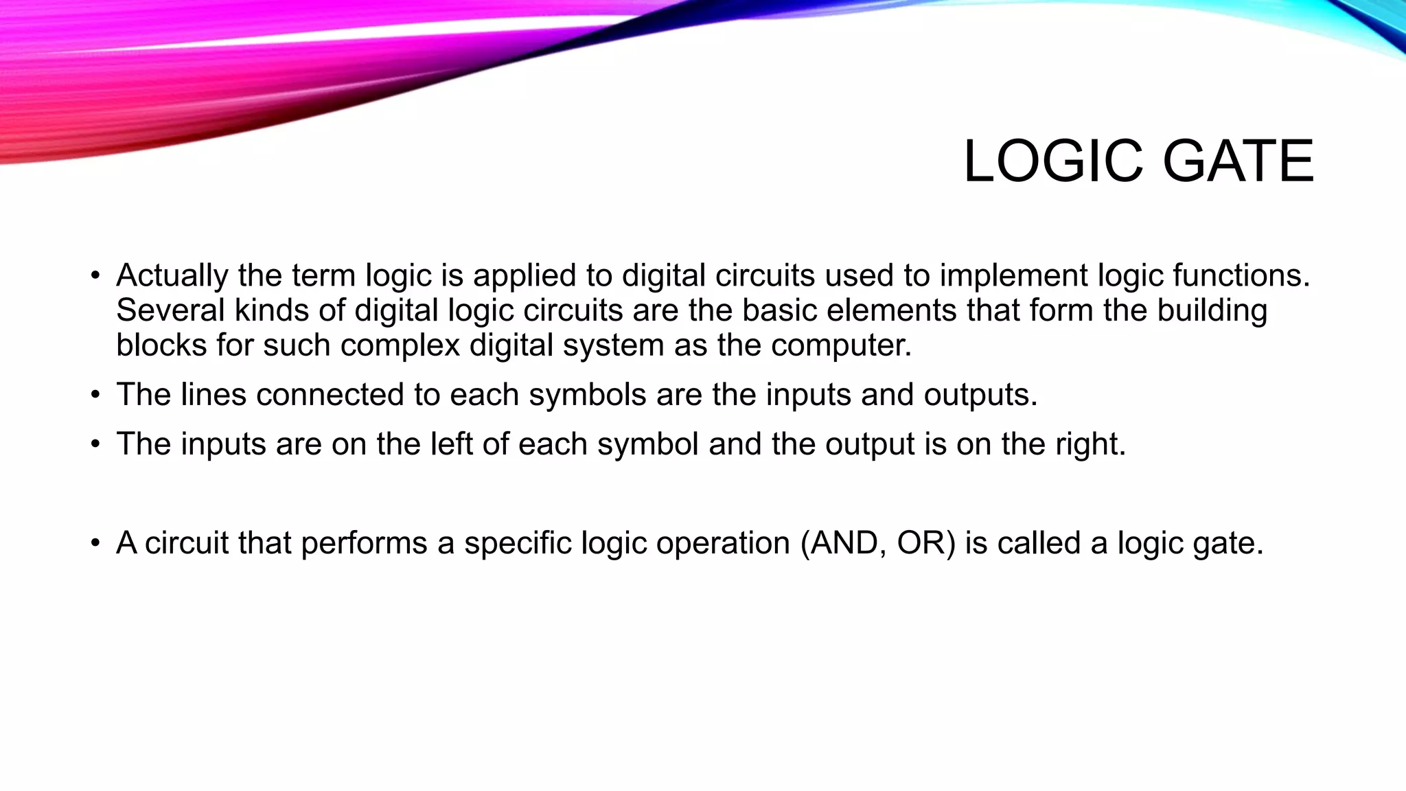
Introduces logic gates as digital circuits for logic functions, with inputs on the left and outputs on the right.
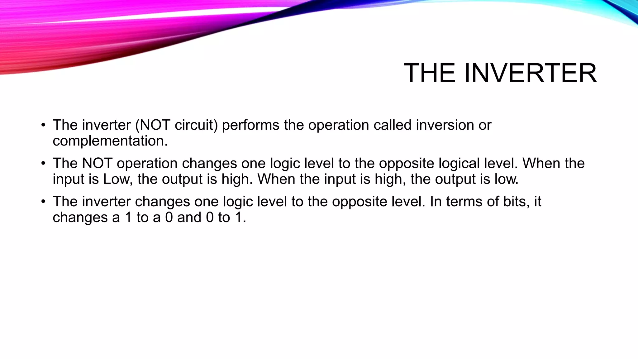
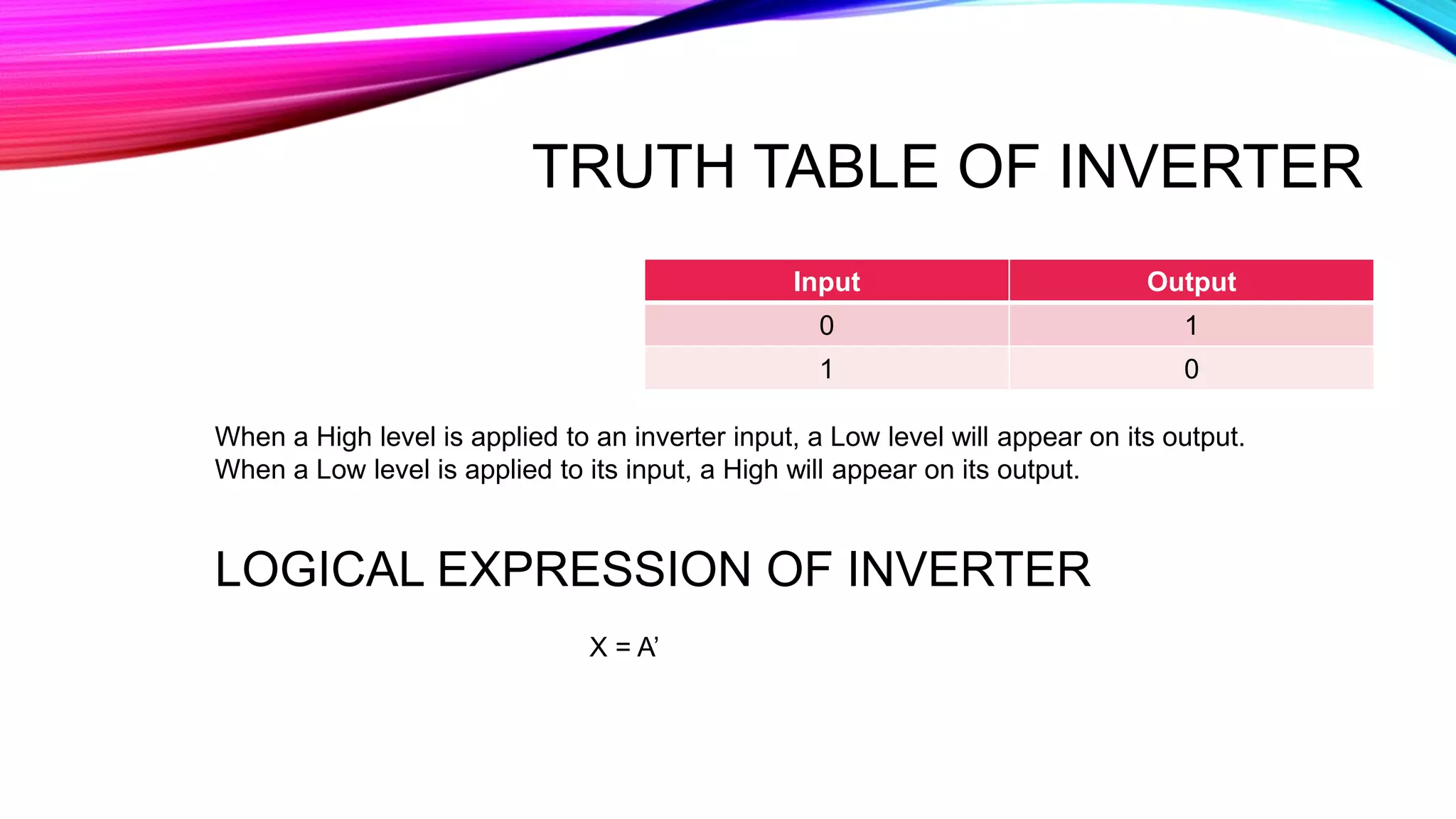
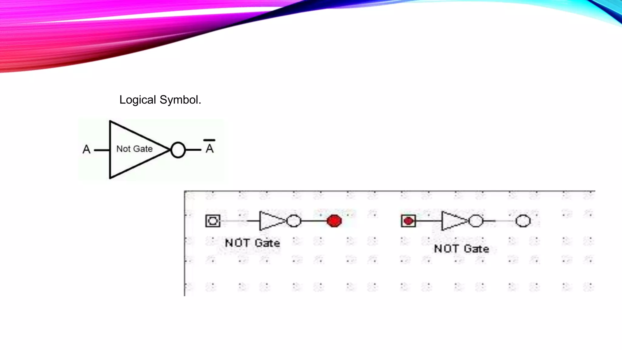
Describes NOT operation that inverts input signals: 0 to 1 and 1 to 0, with a truth table showing the output results.
Displays the logical symbol for the inverter.
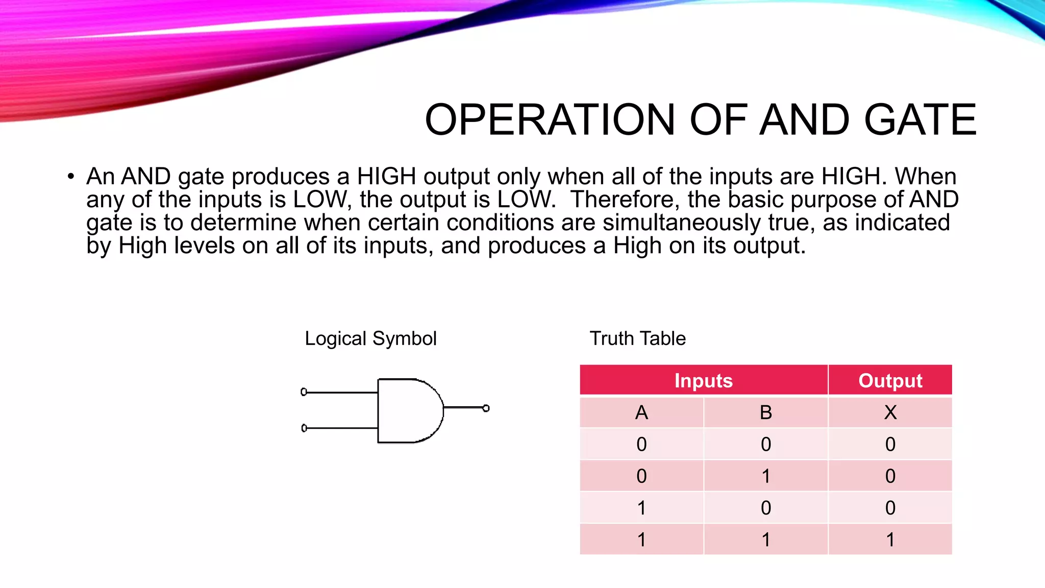
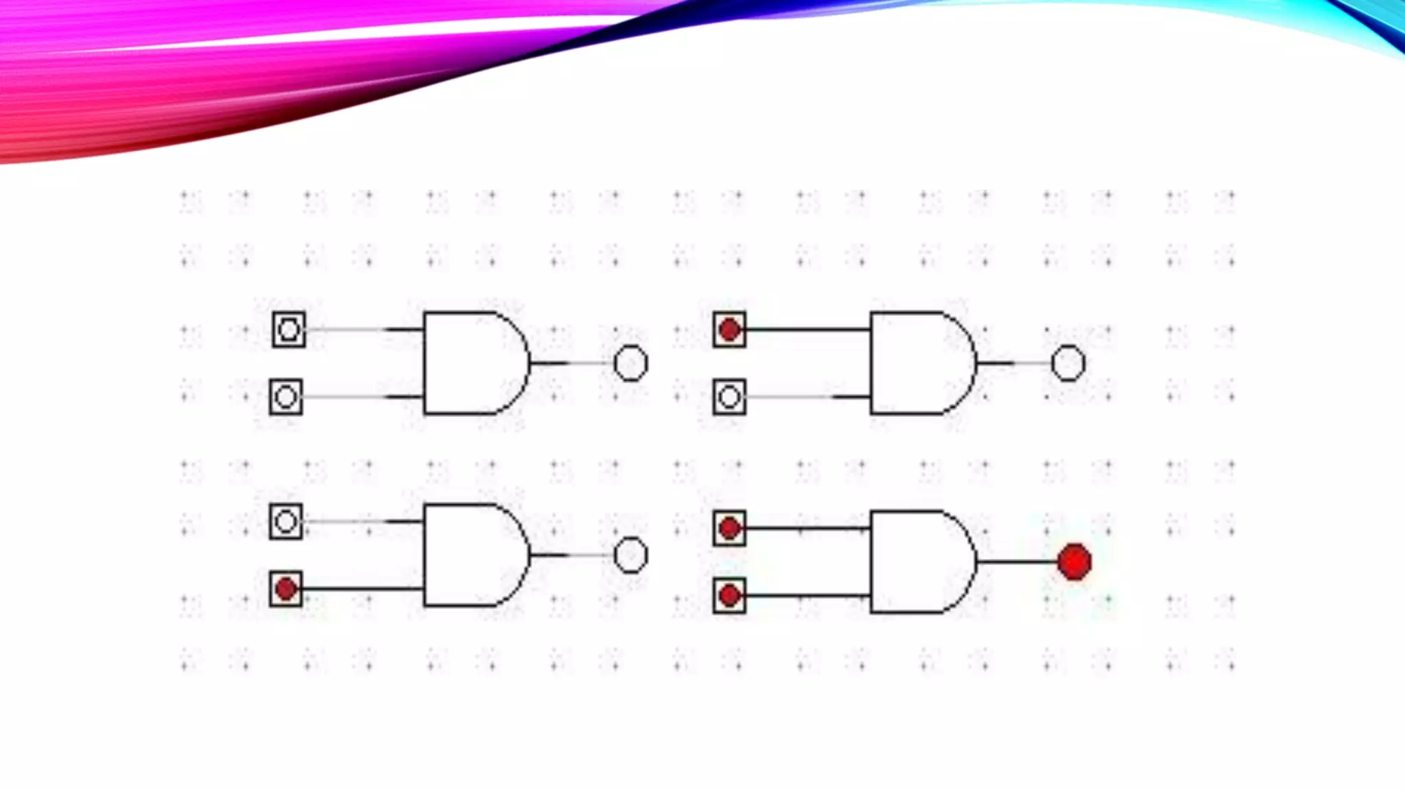
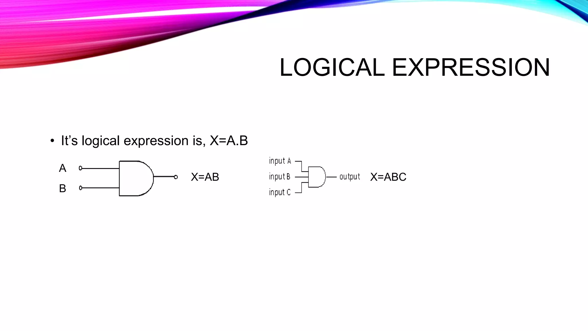
Explains AND gate operation producing high output when all inputs are high, with input-output combinations and logical expression.
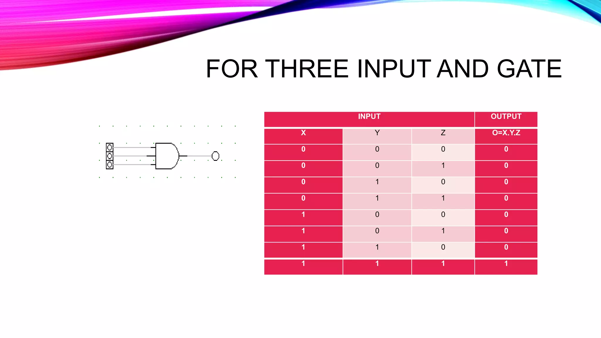
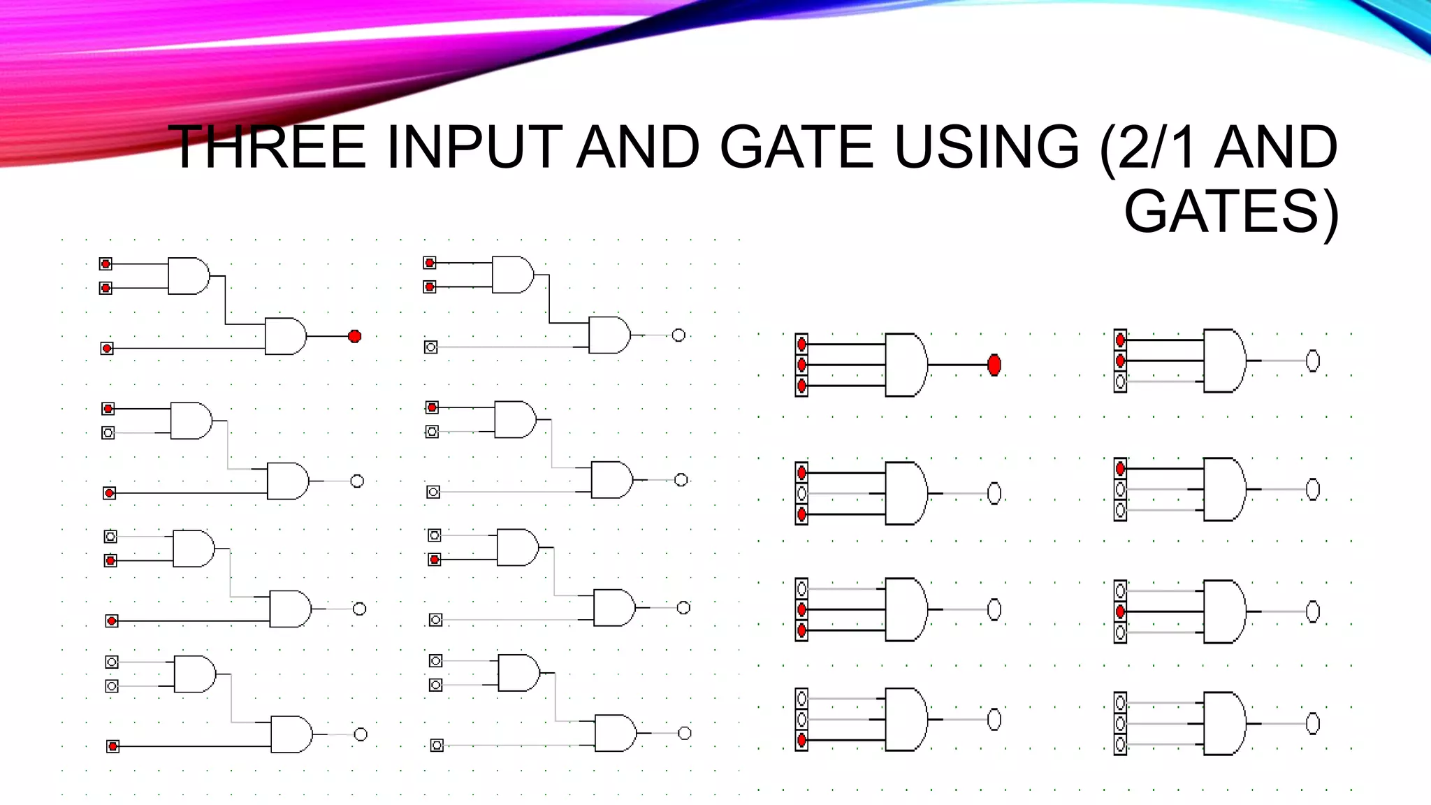
Presents outputs for three input AND gate combinations and explains construction using 2/1 AND gates.
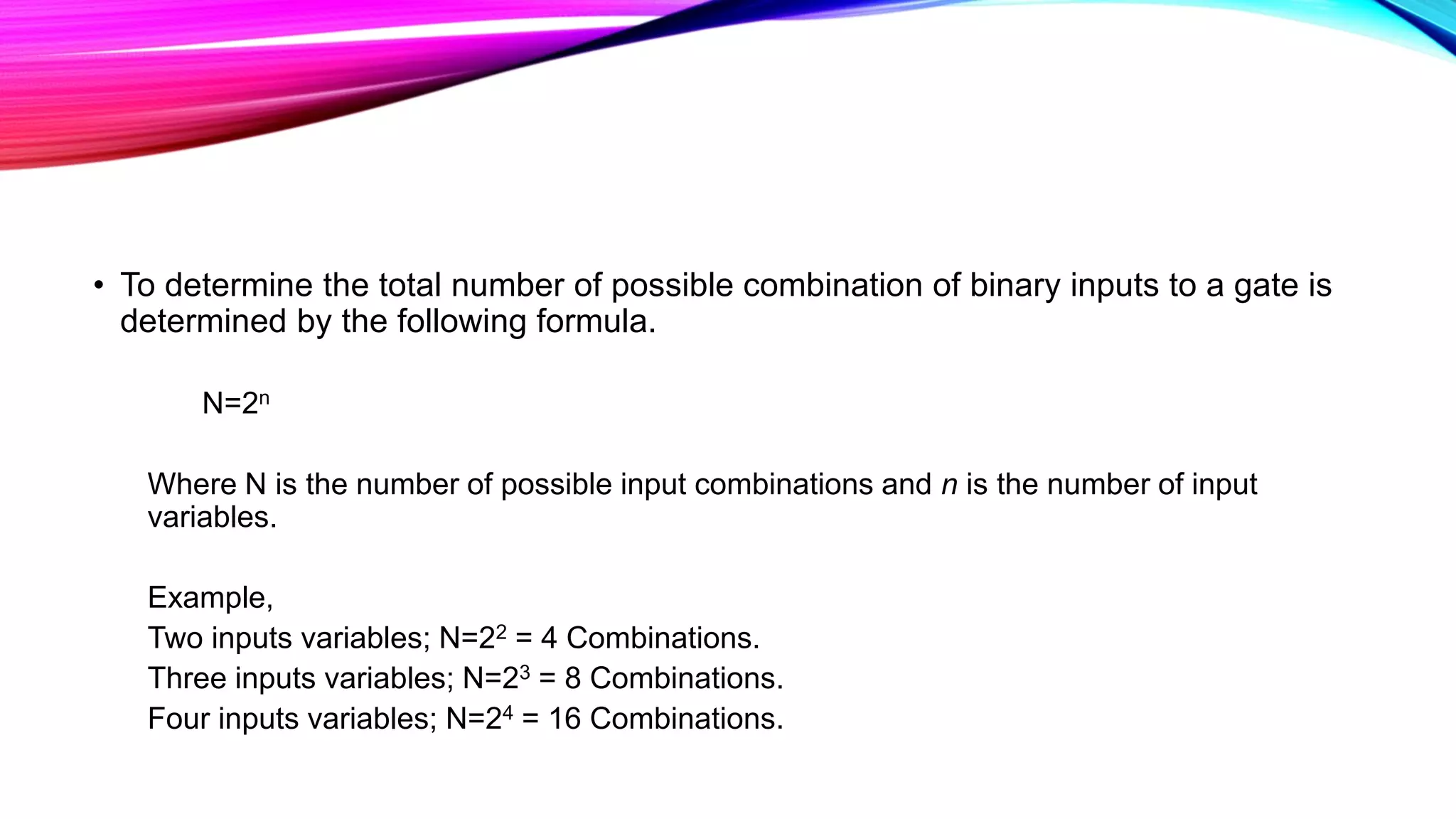
Provides a formula (N=2^n) to calculate input combinations based on the number of input variables.
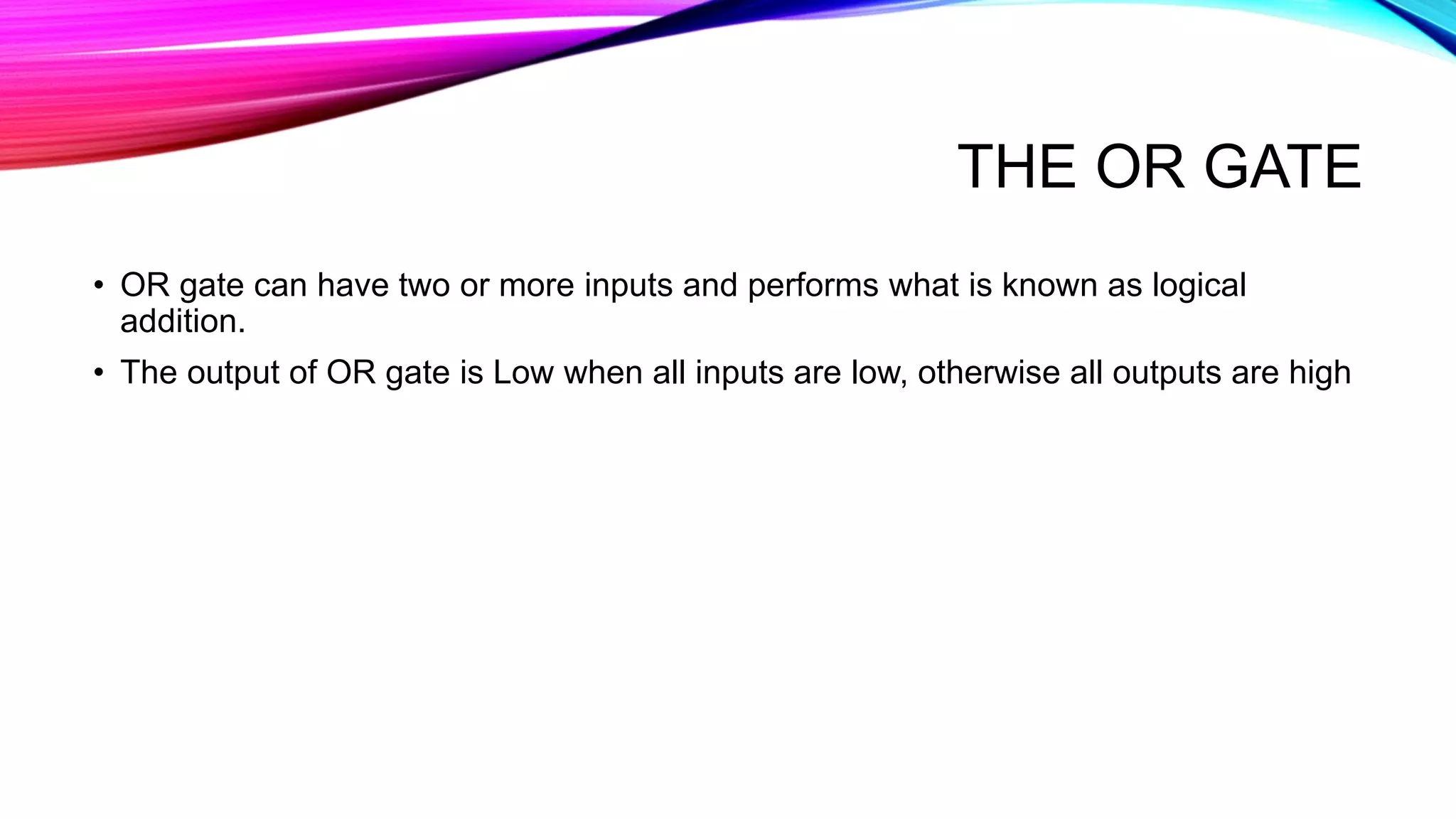
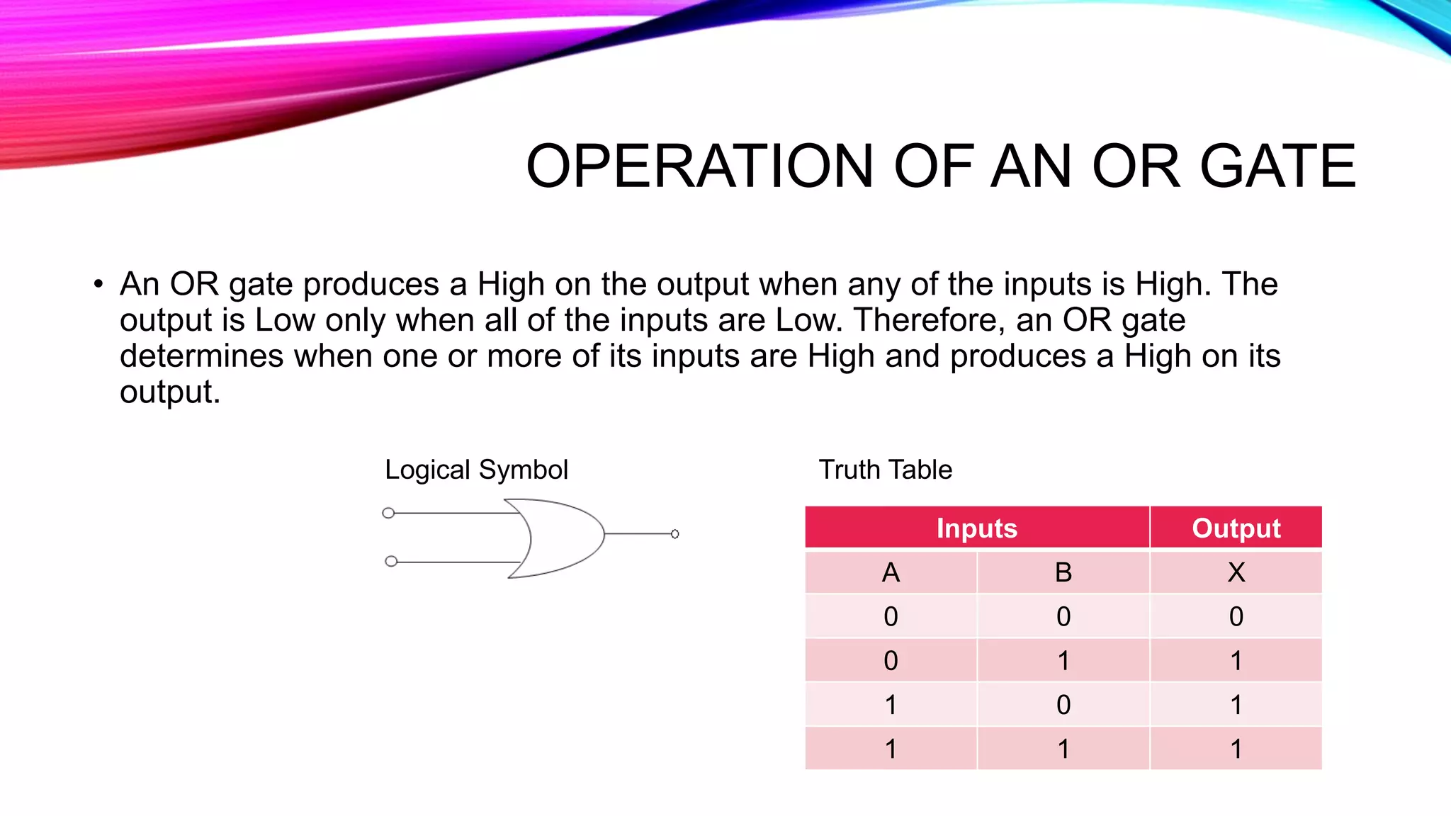
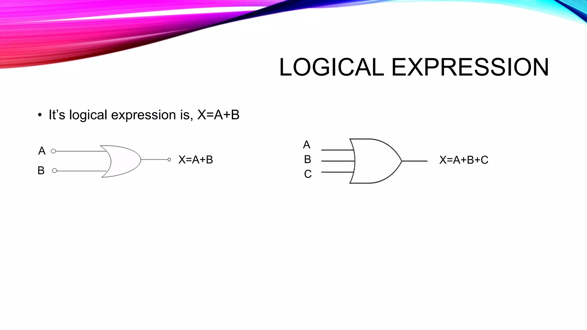
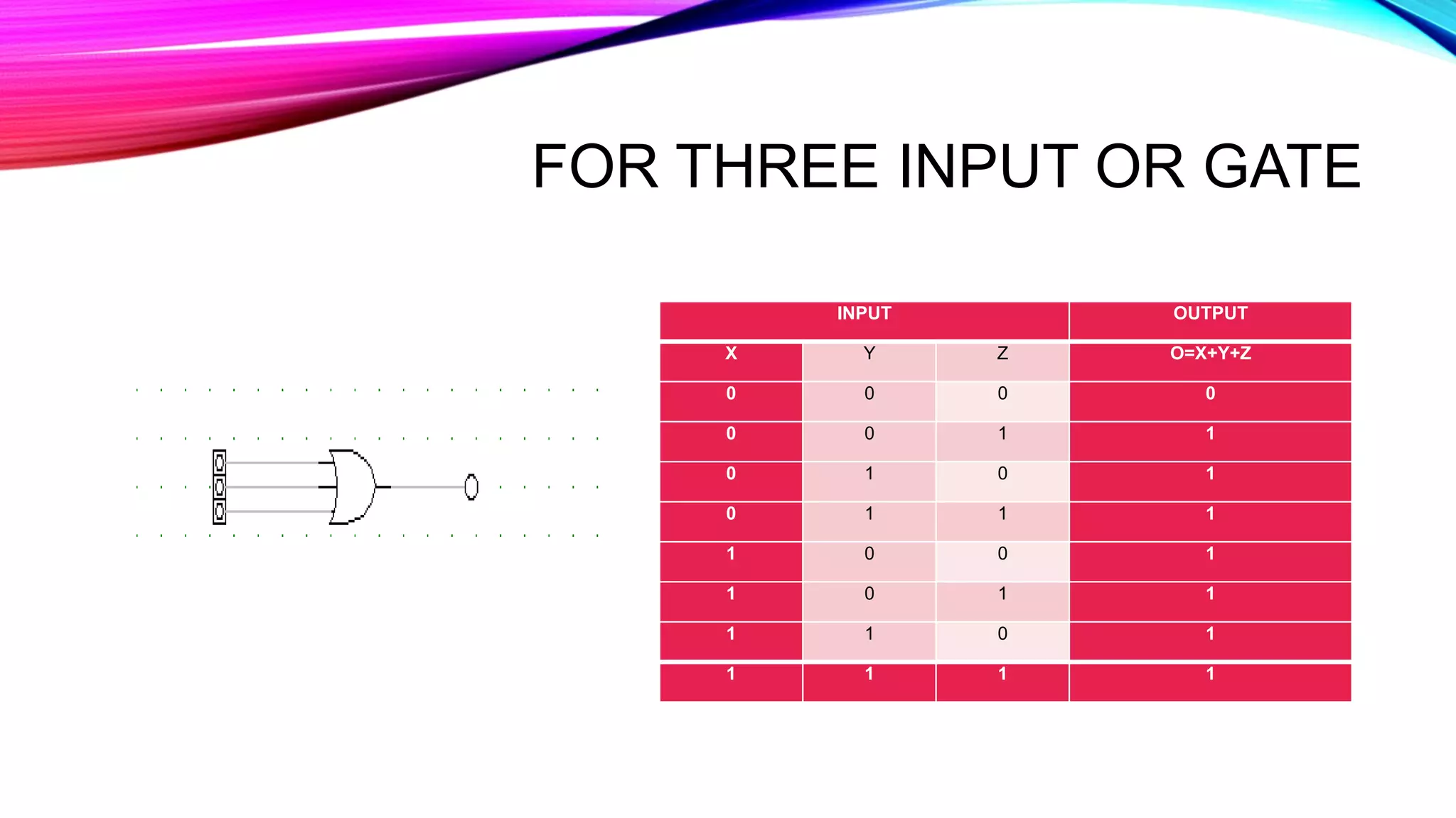
Describes OR gate that outputs high when any input is high, with truth tables and logical expressions.
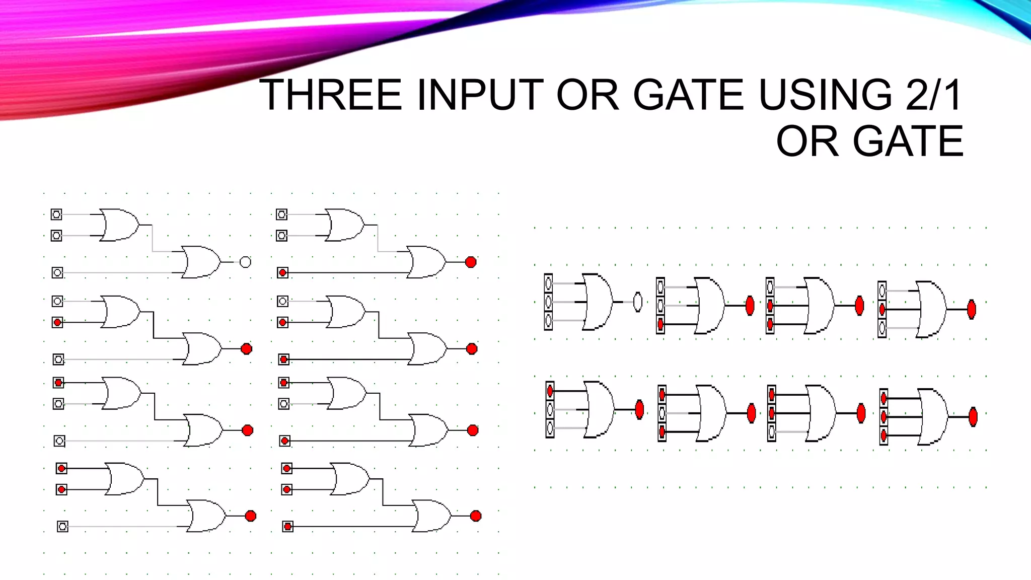
Shows output results for three input OR gate and its construction using 2/1 OR gates.
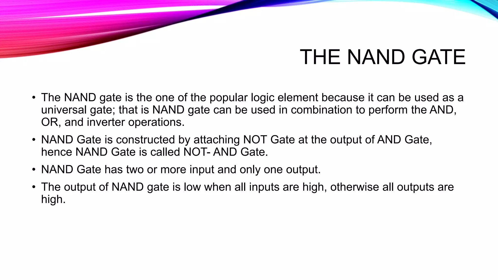
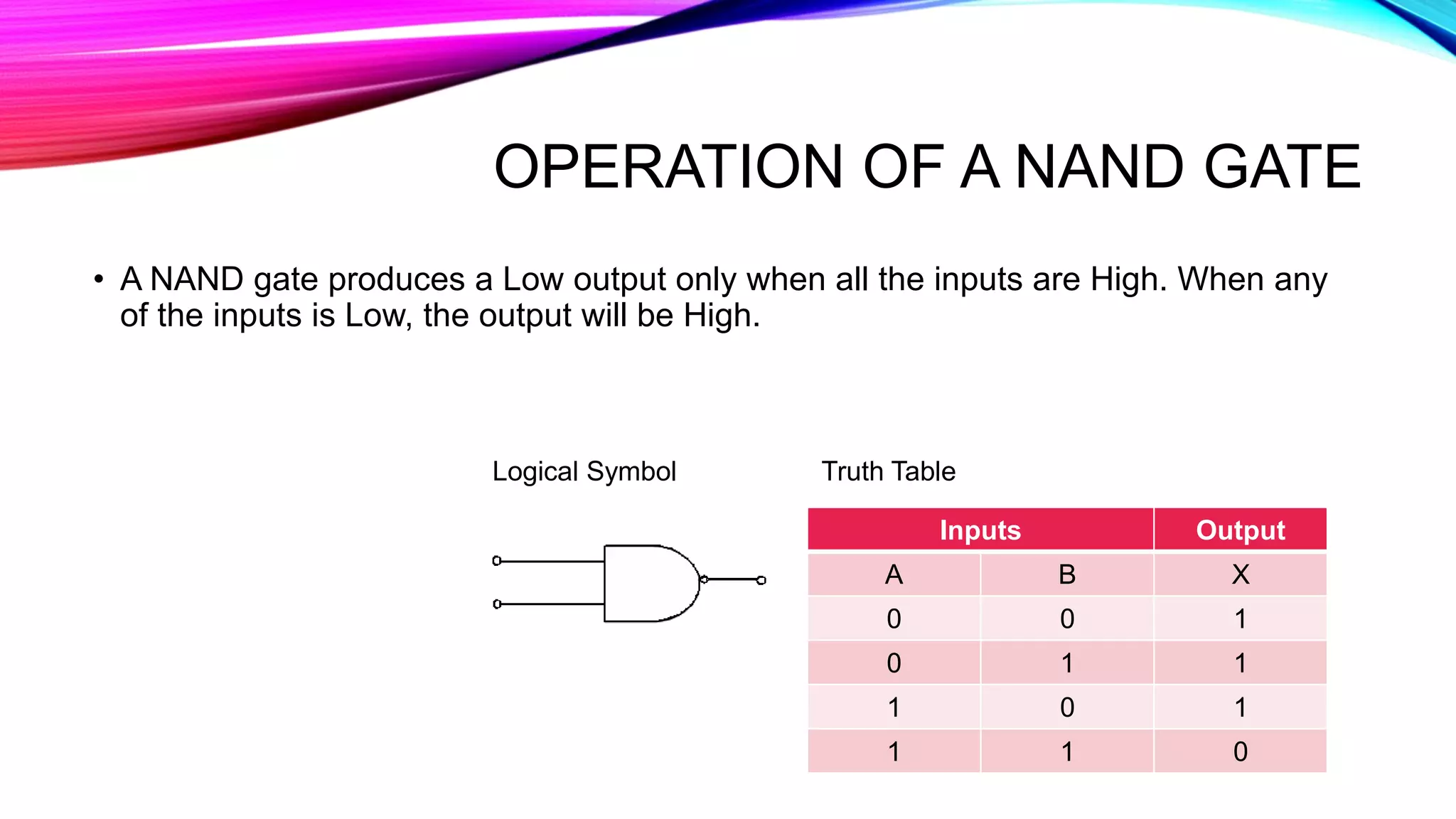
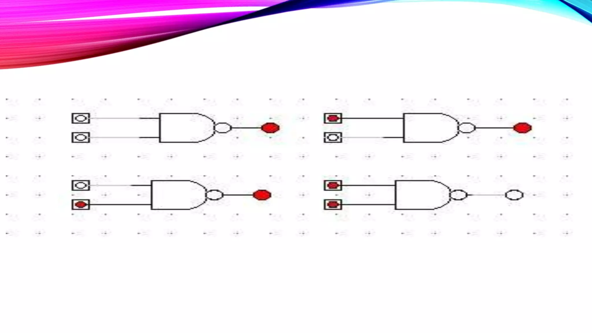
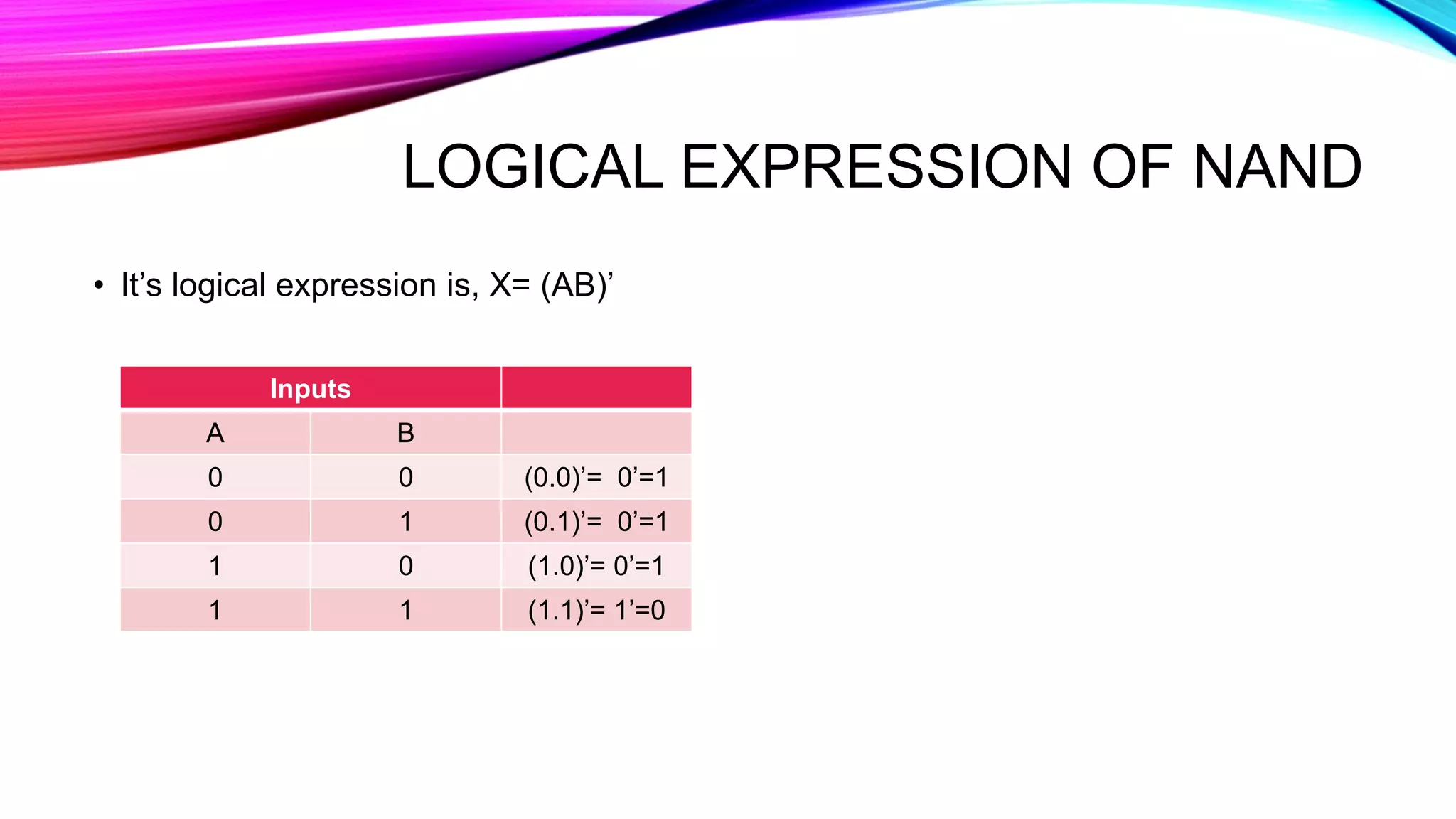
Explains NAND gate as universal gate formed from AND with an inverter, with truth table and logical expression.
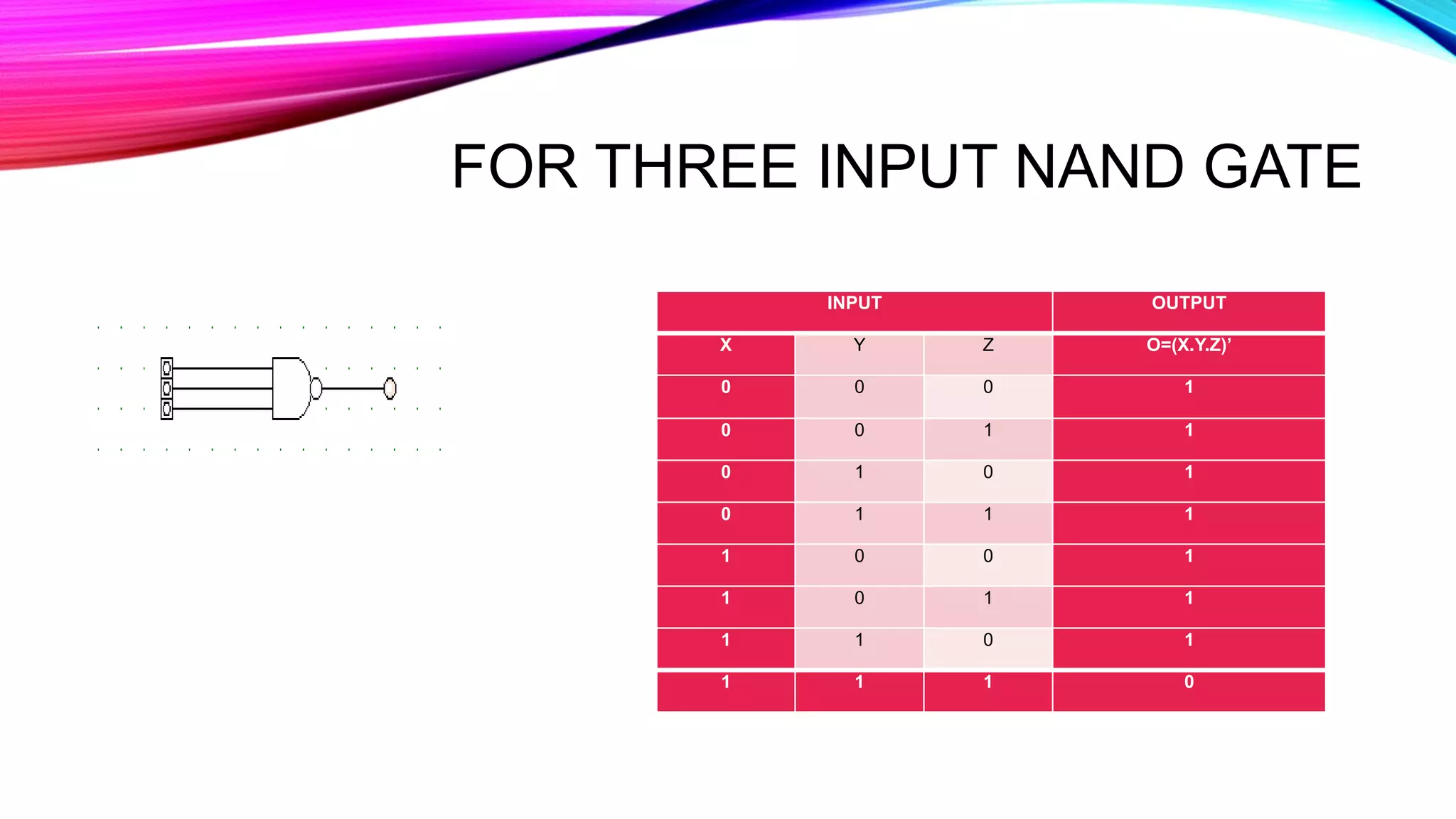
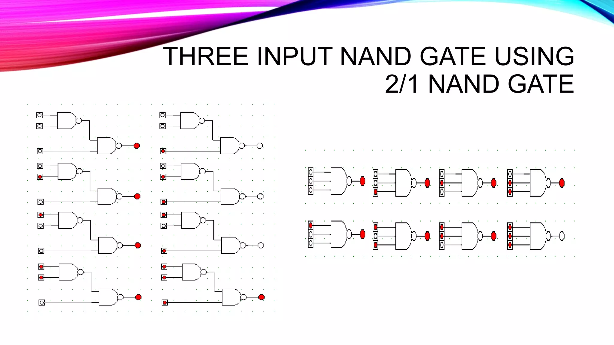
Illustrates output results for three input NAND gate and its construction using 2/1 NAND gates.
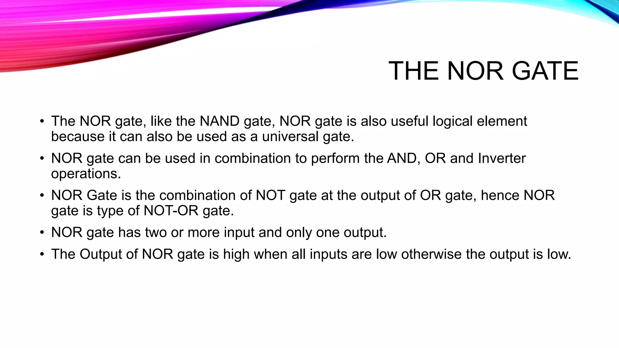
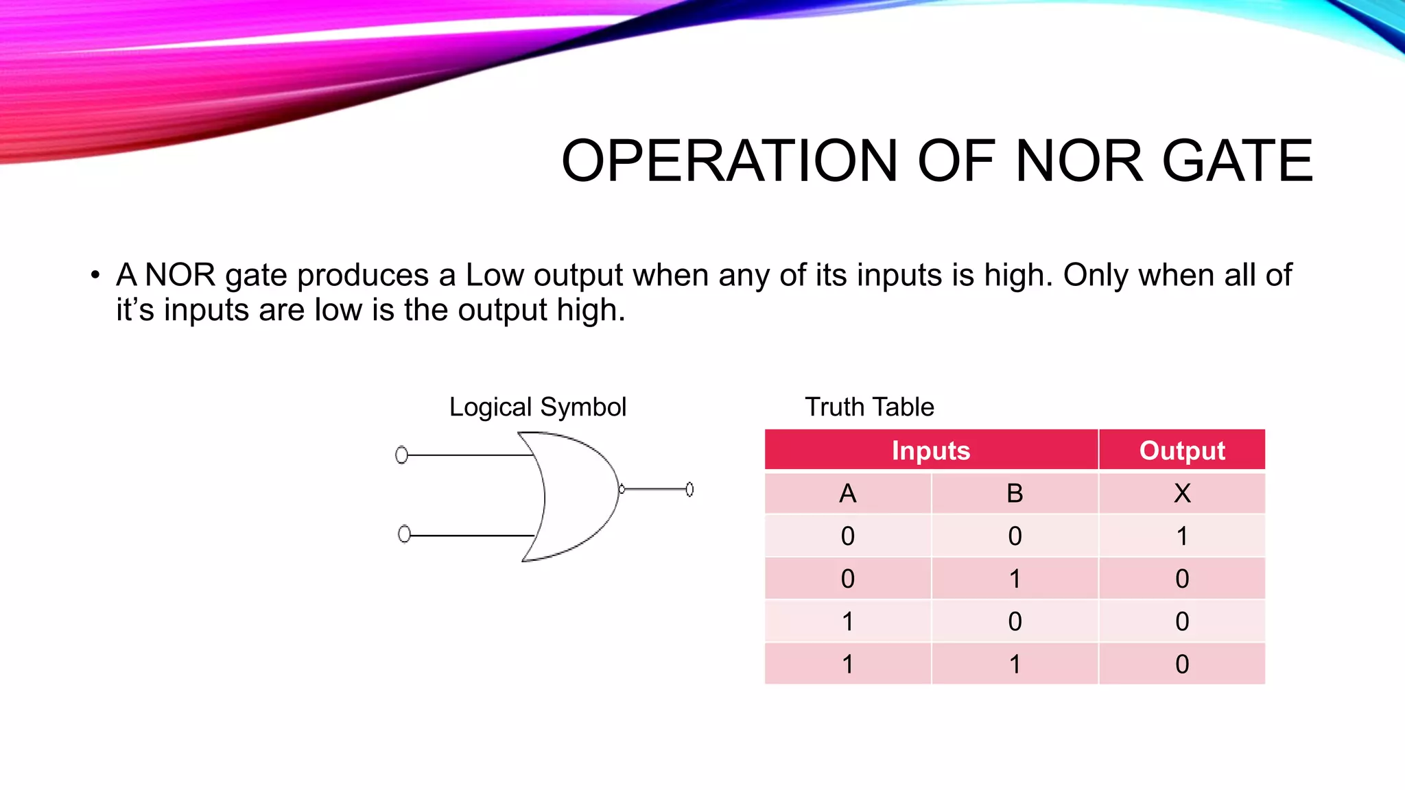
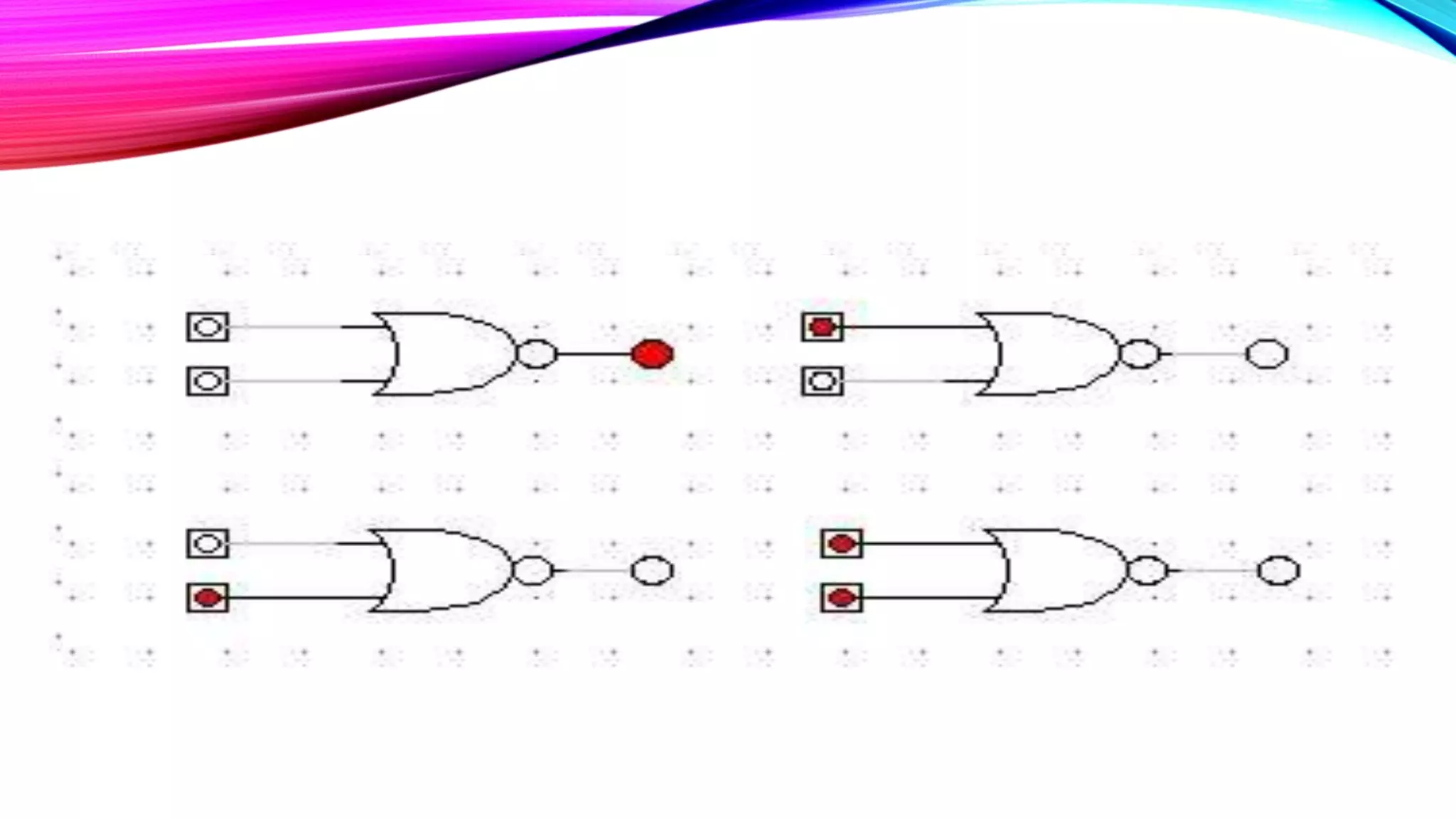
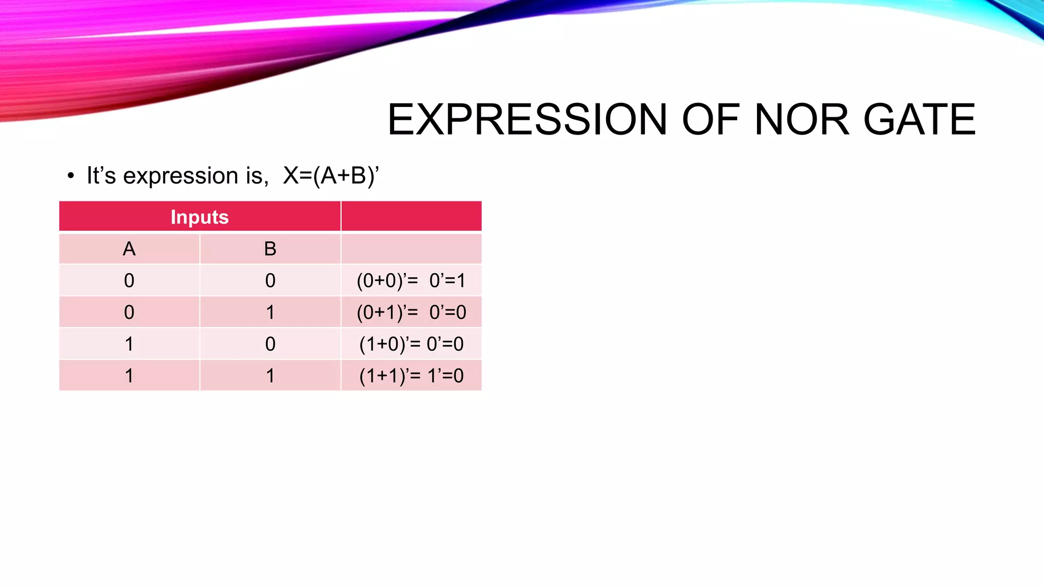
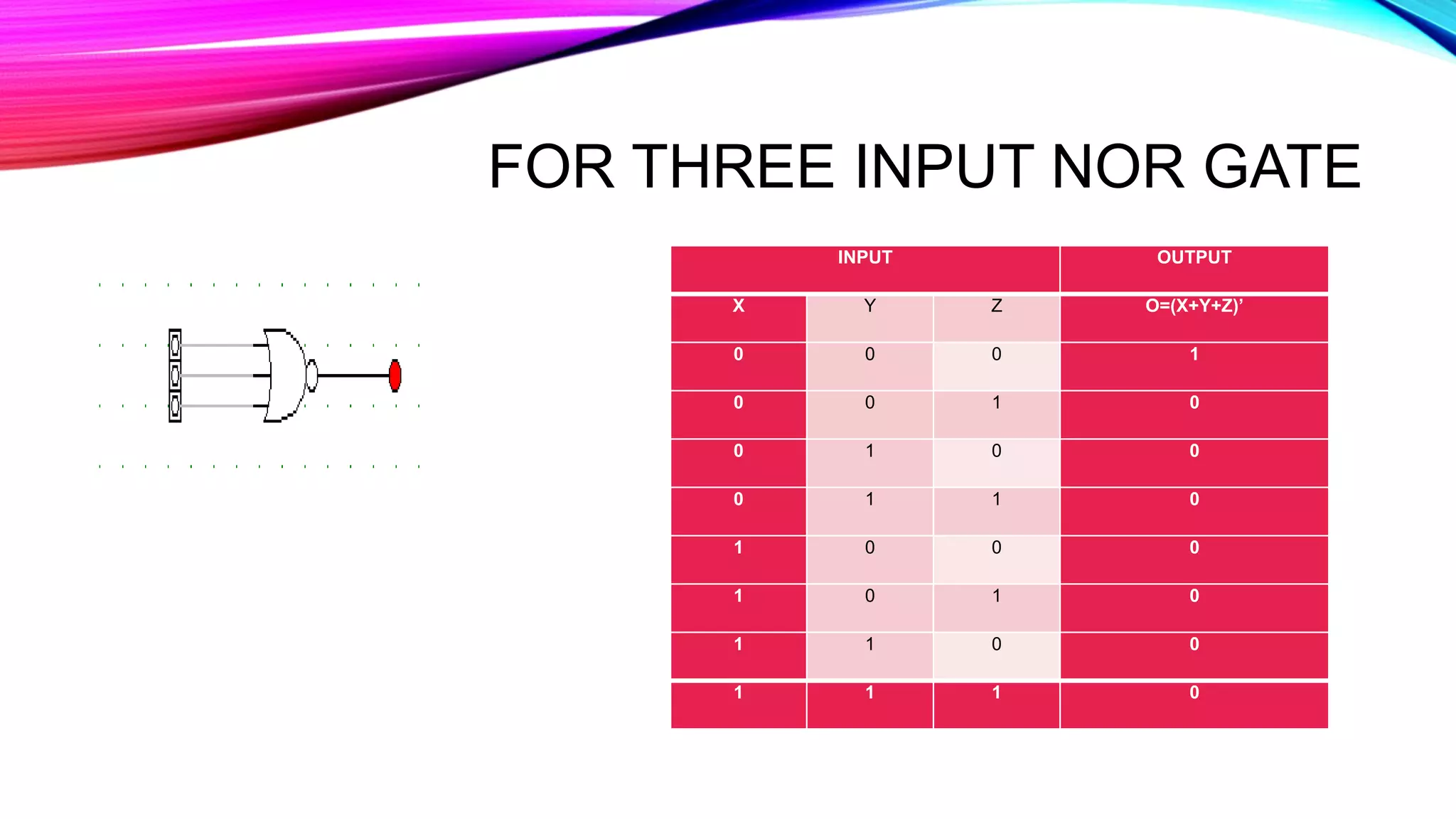
Describes NOR gate functionality similar to NAND, including logical structure and output results.
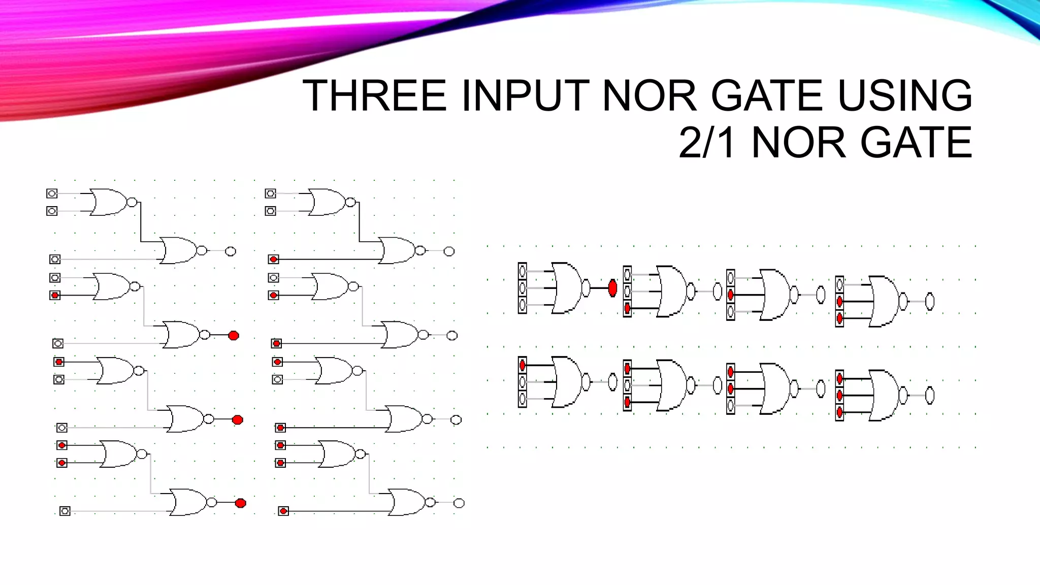
Shows three input NOR gate results and its design using 2/1 NOR gates.
Details the exclusive-OR gate with truth table and logical expression highlighting unique outputs.
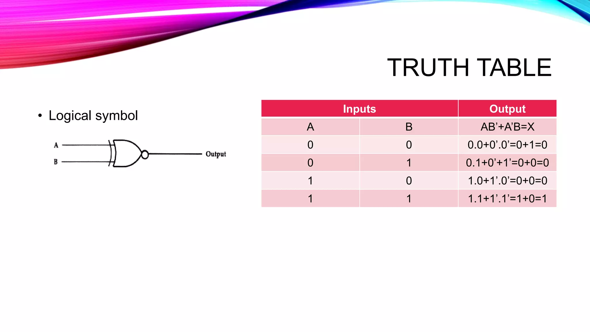
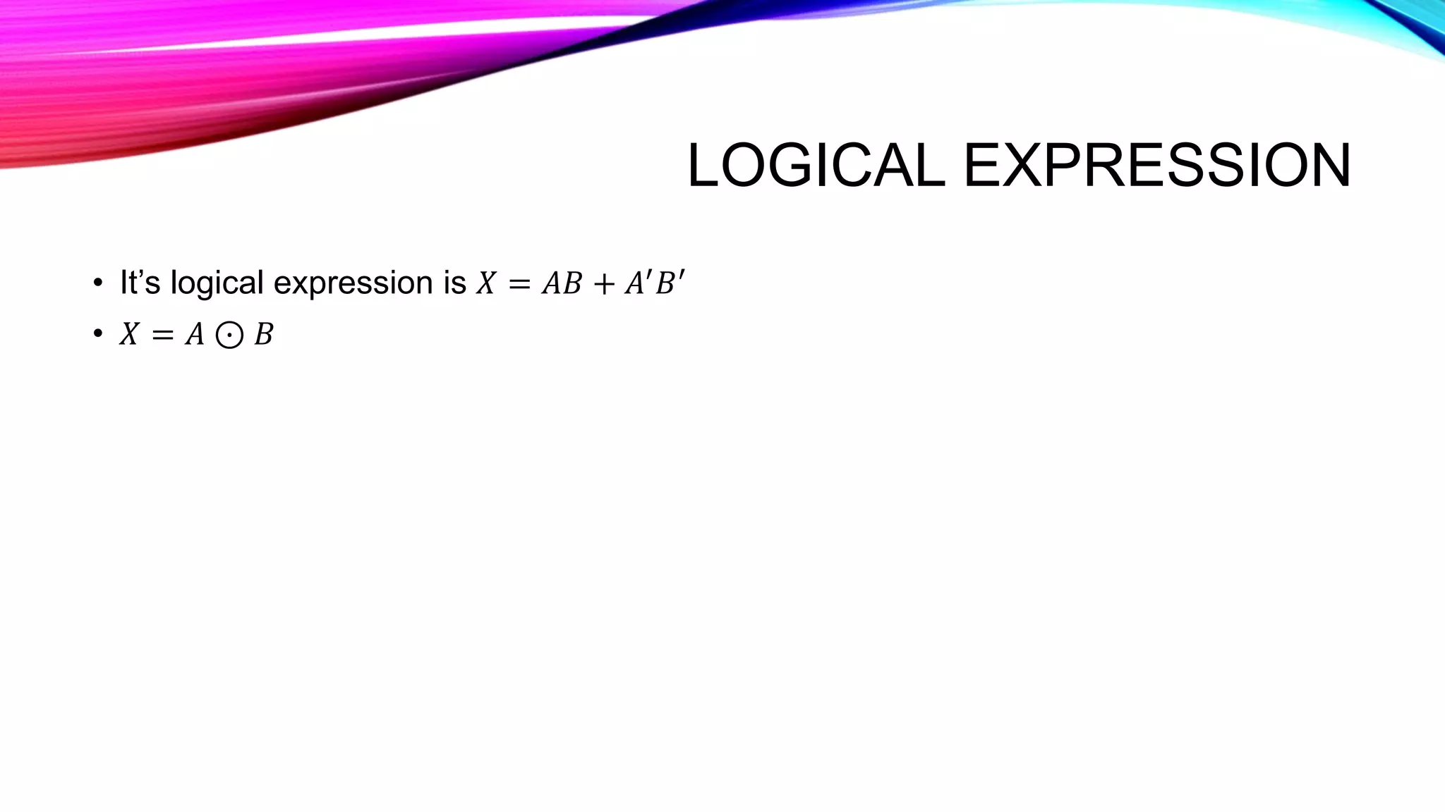
Describes exclusive-NOR gate as the complement of EX-OR, with truth tables and logical expression.