Downloaded 838 times
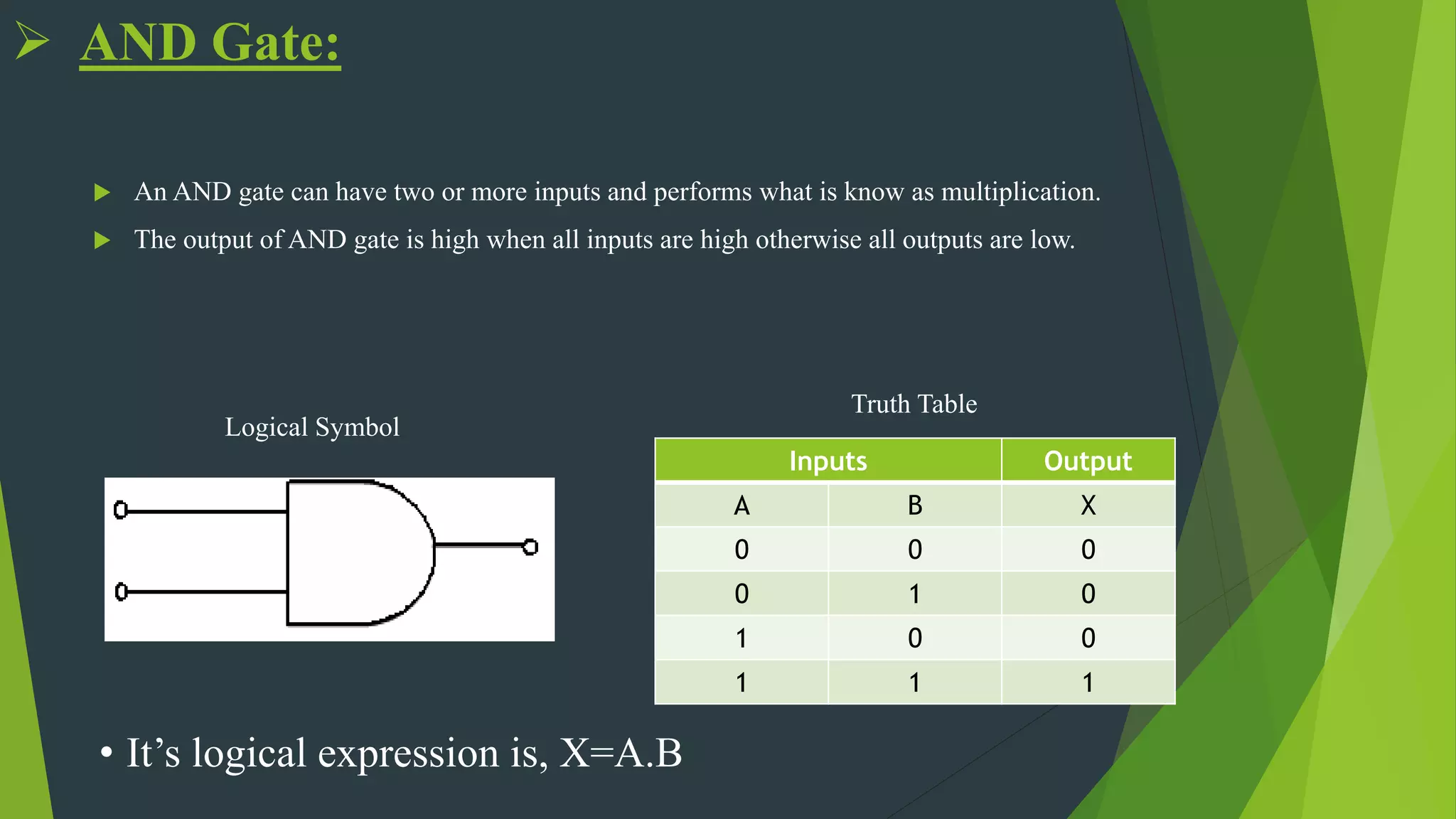
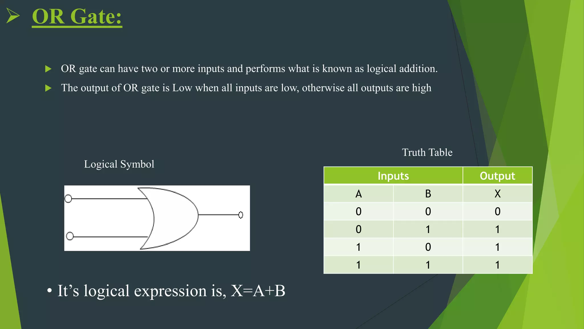
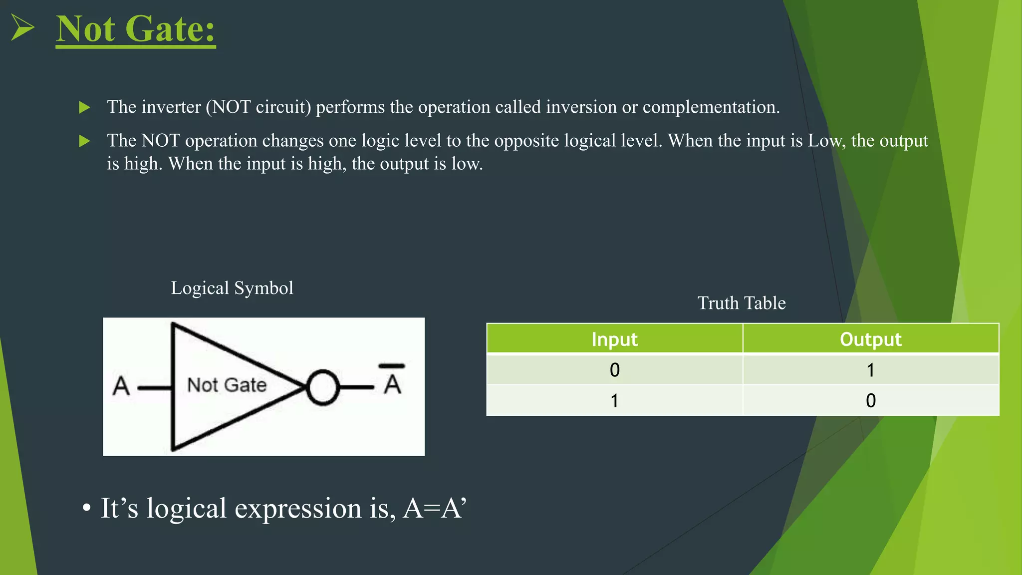
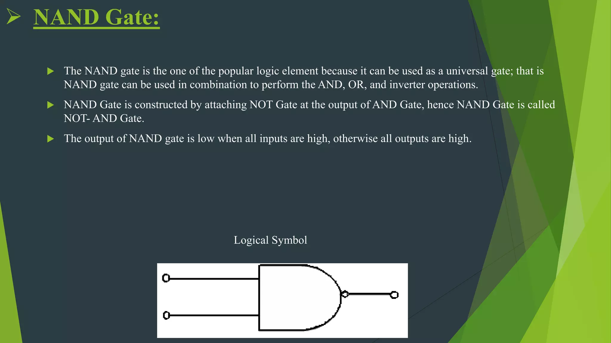
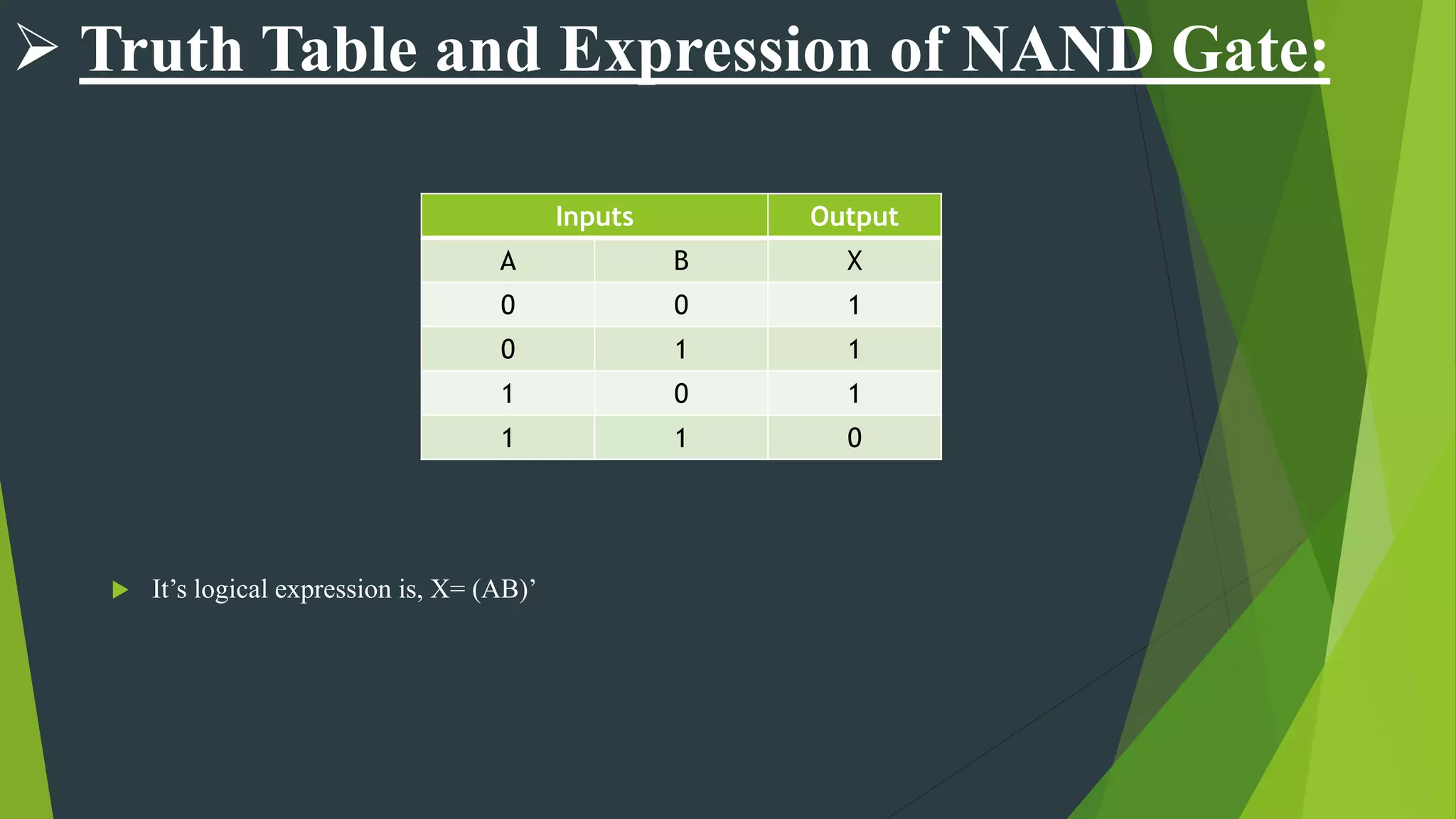
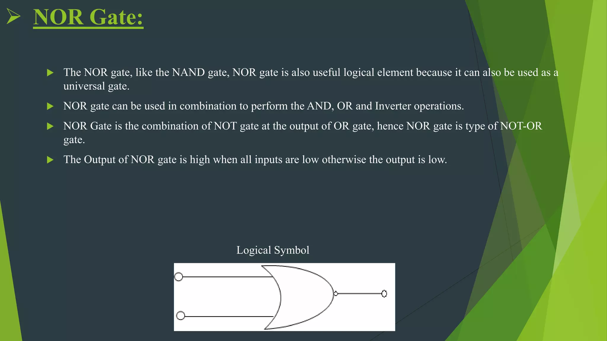
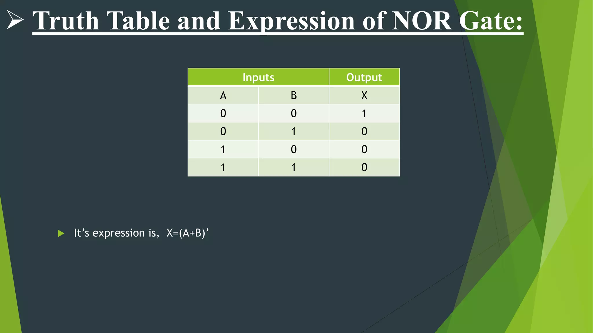
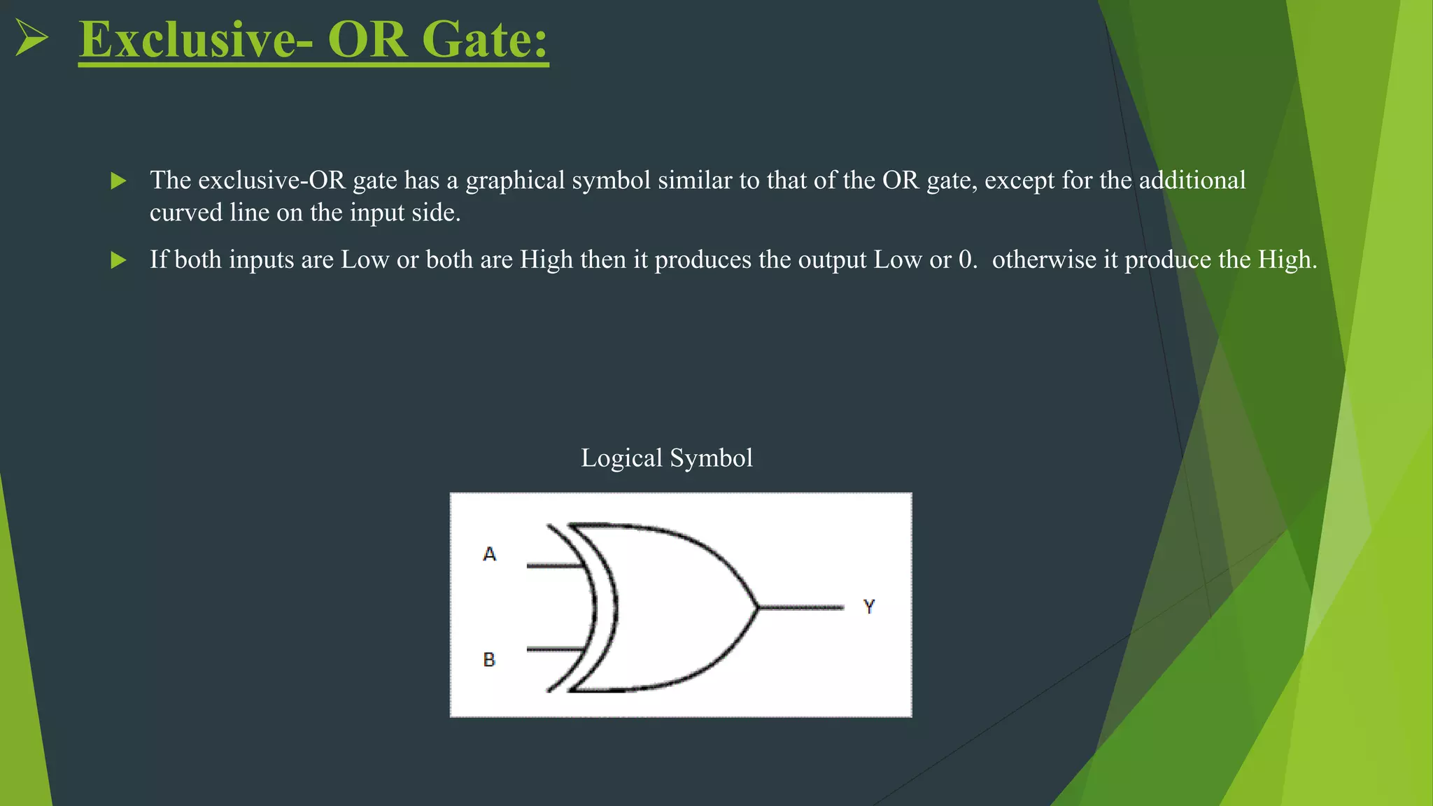
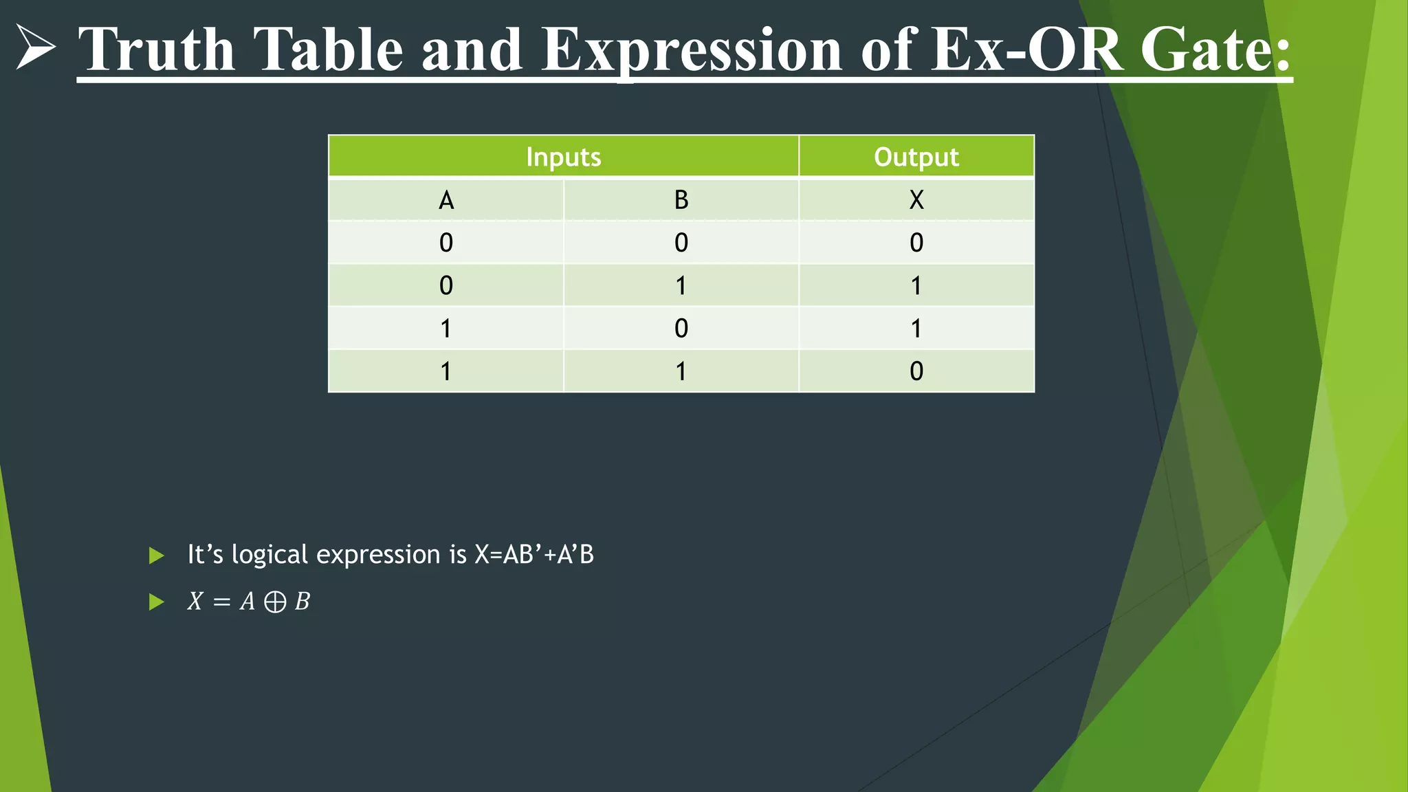
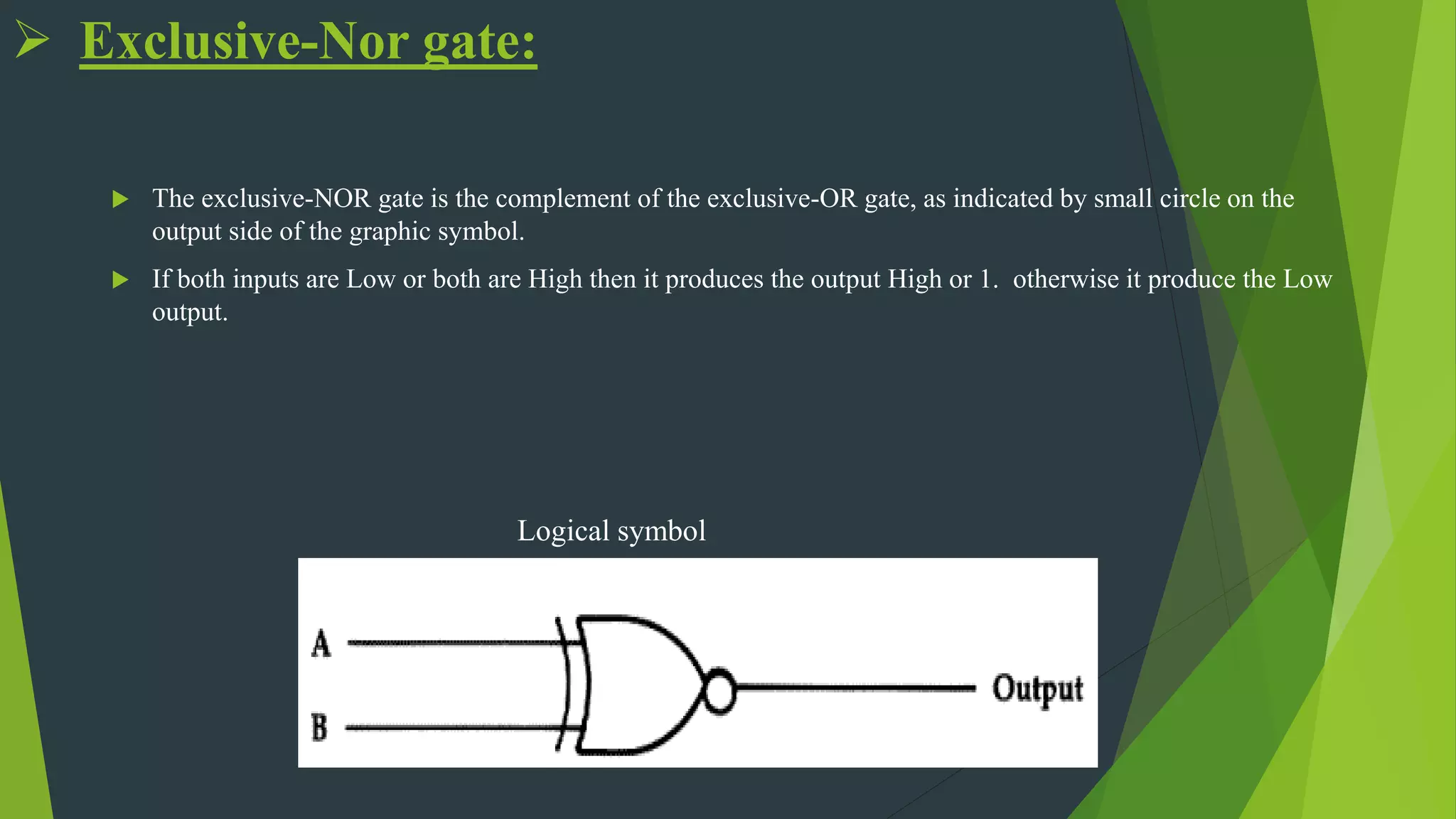
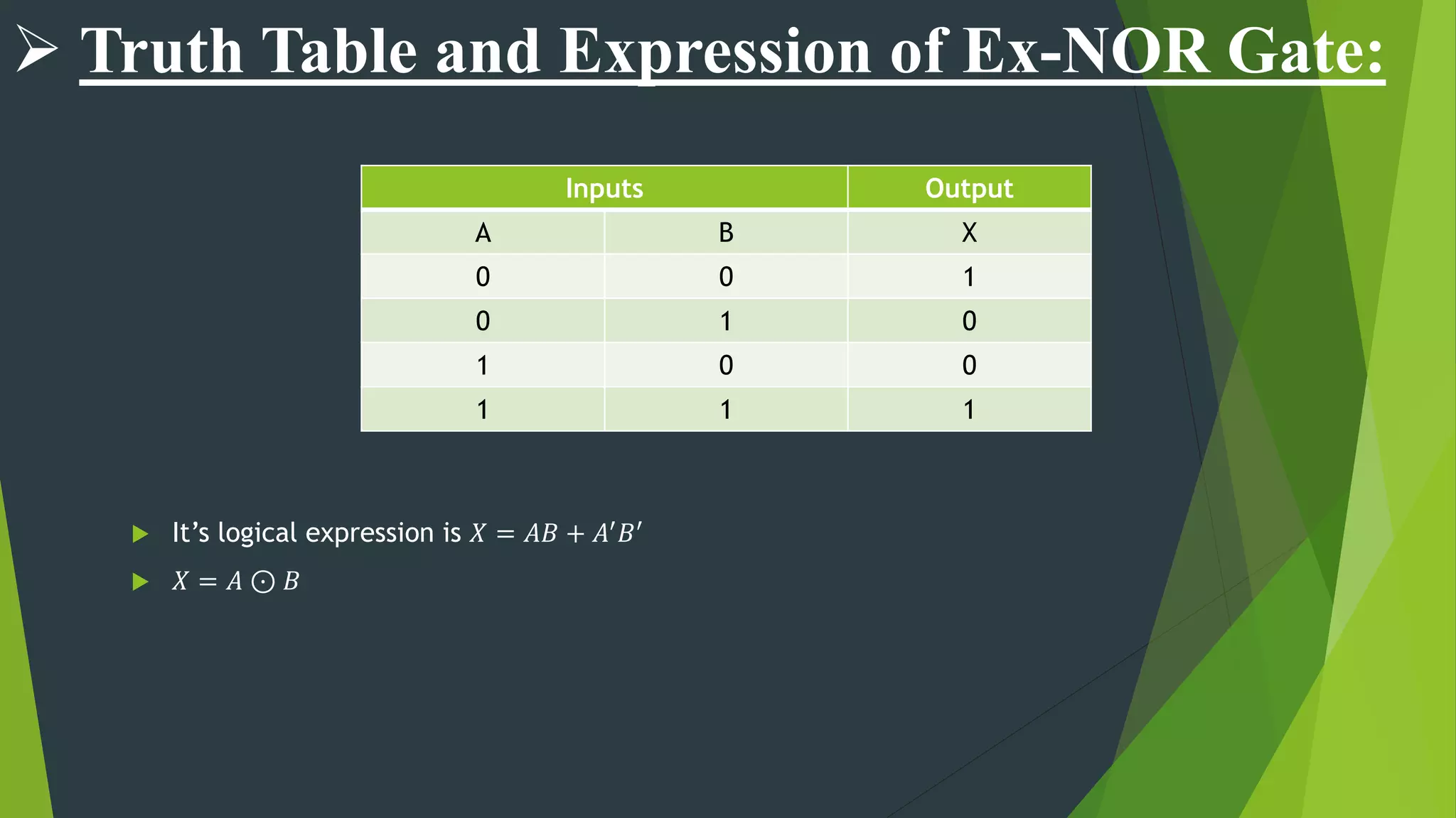

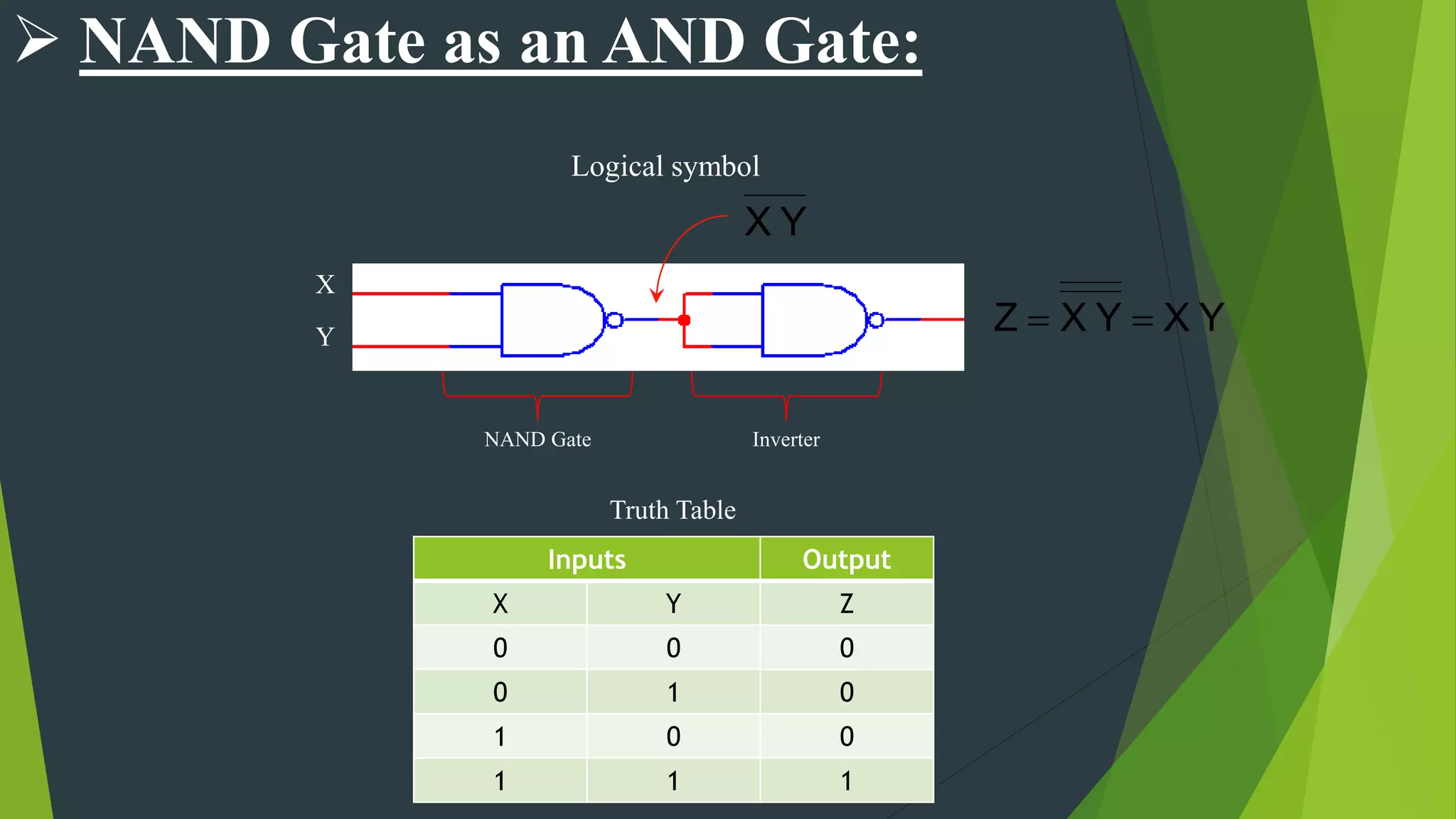
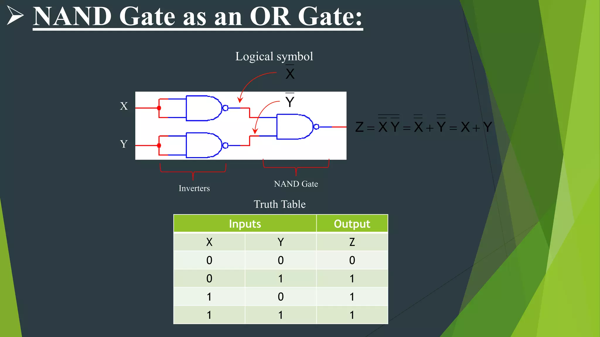
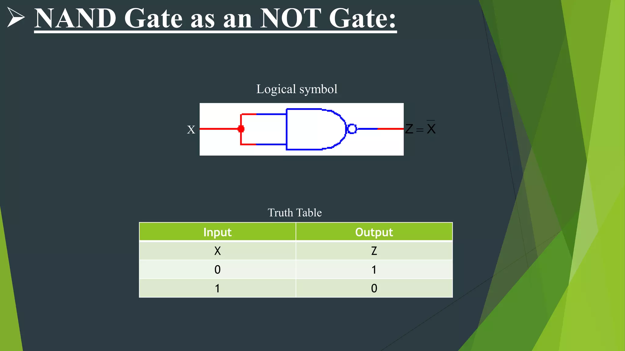
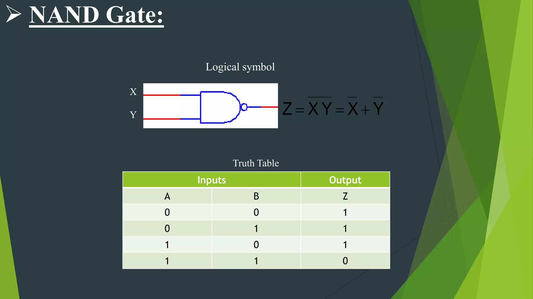
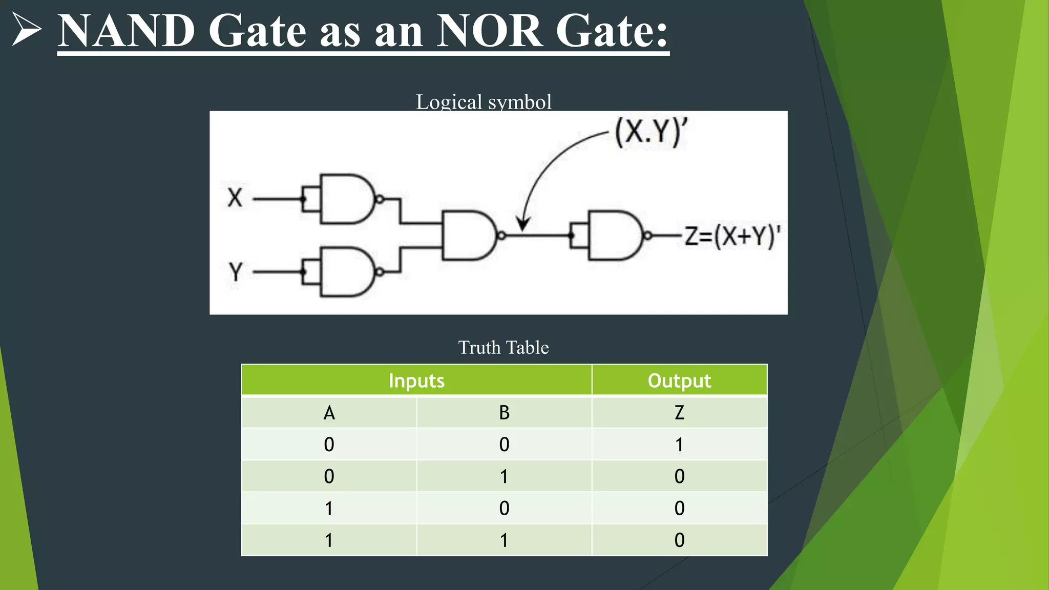
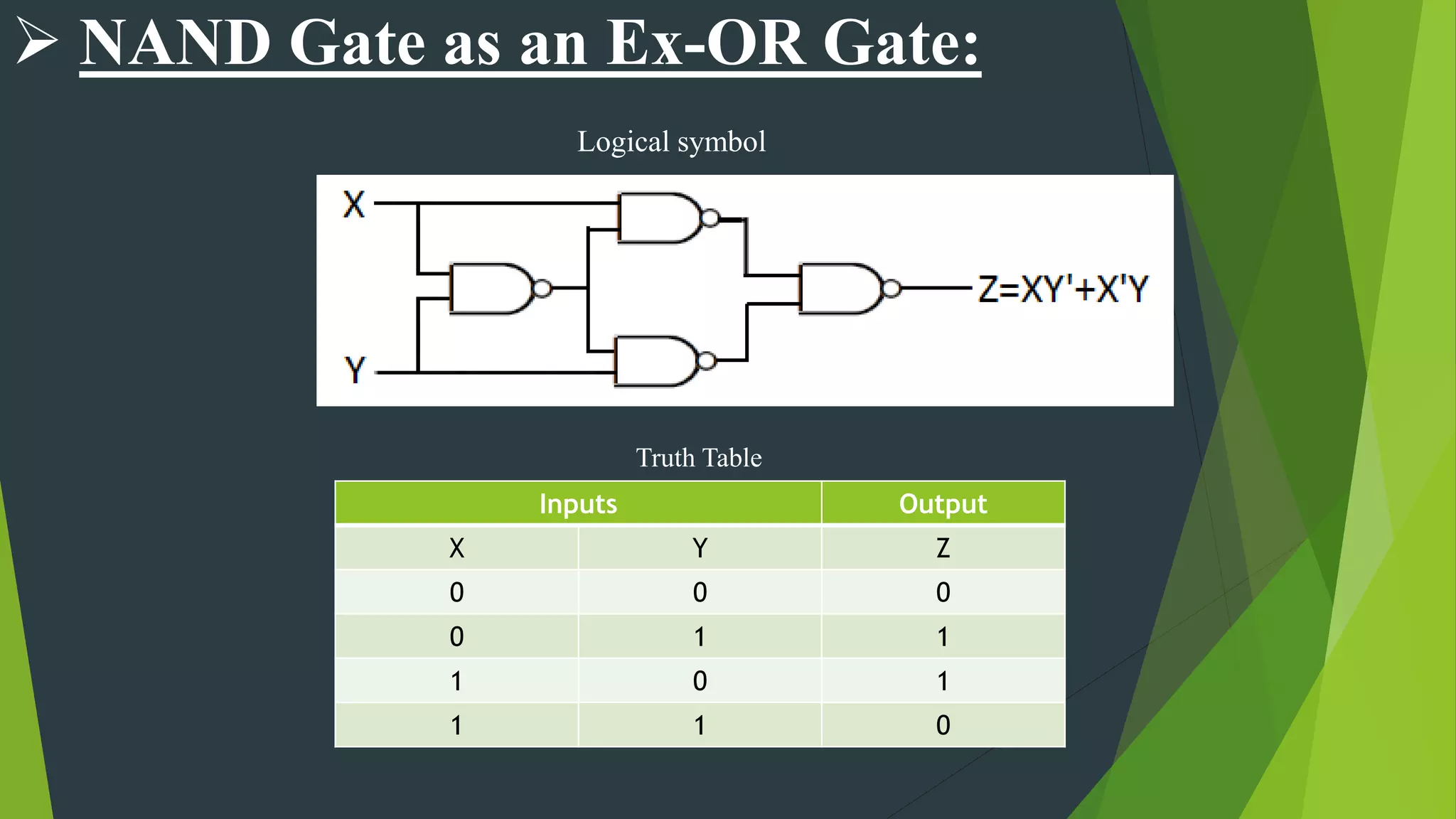
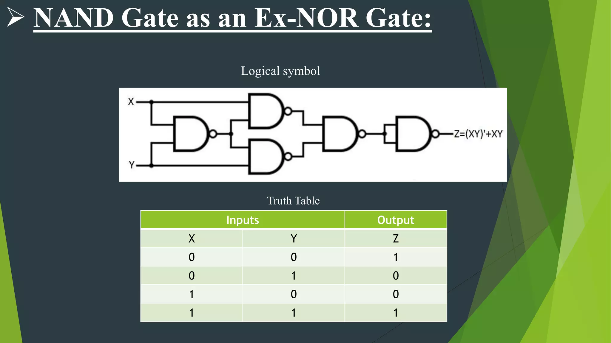
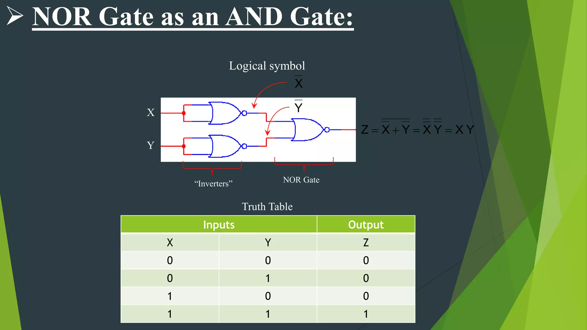
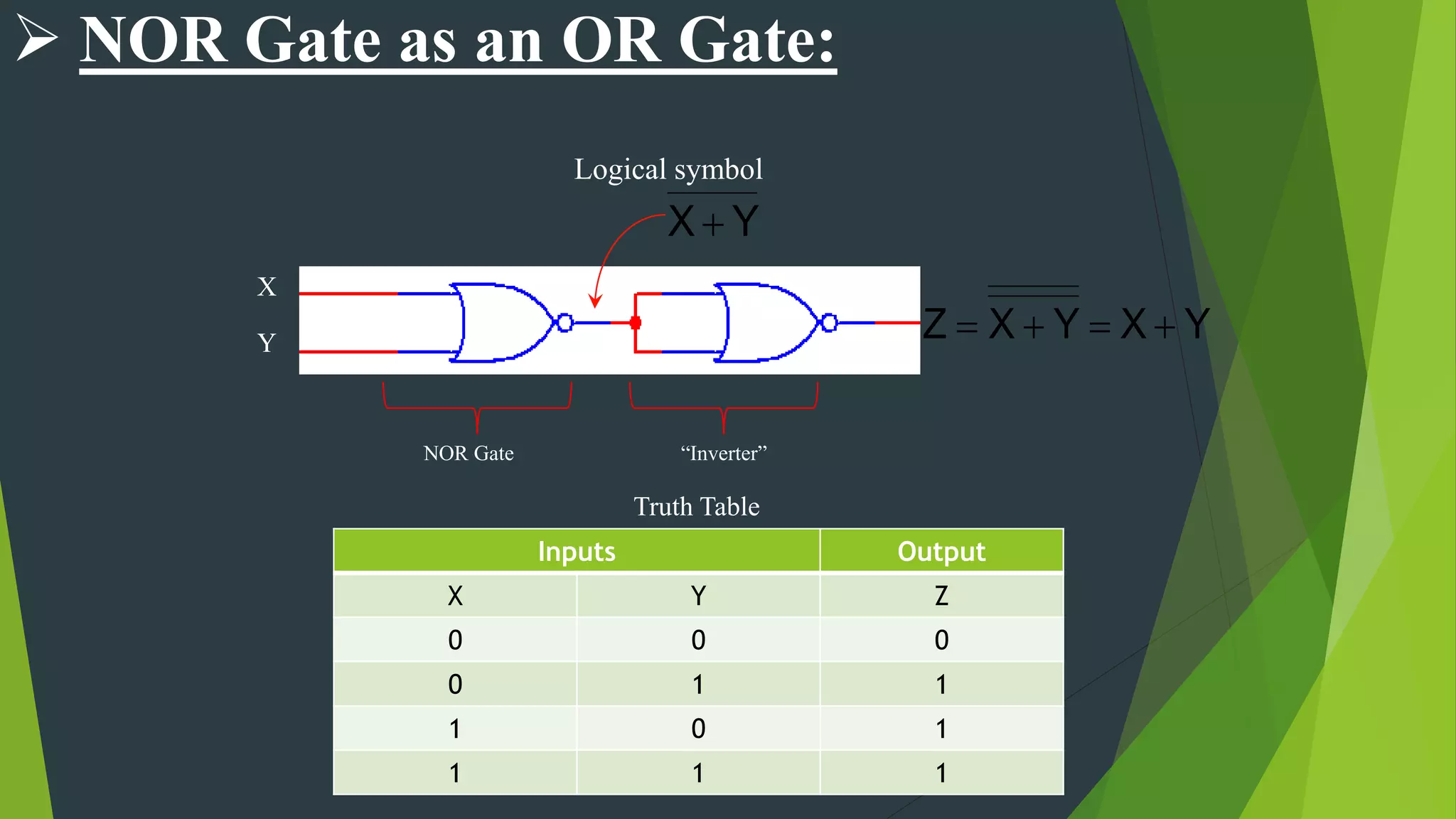

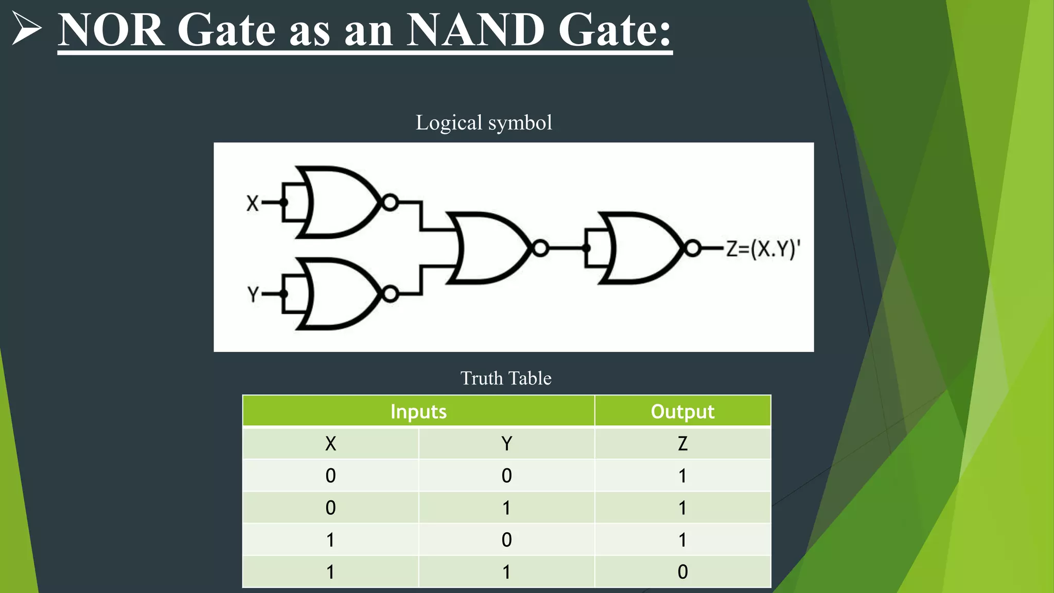
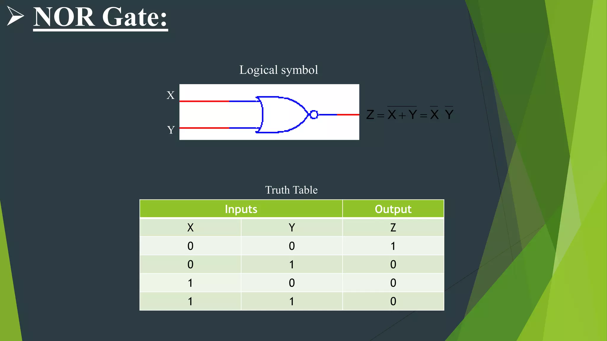
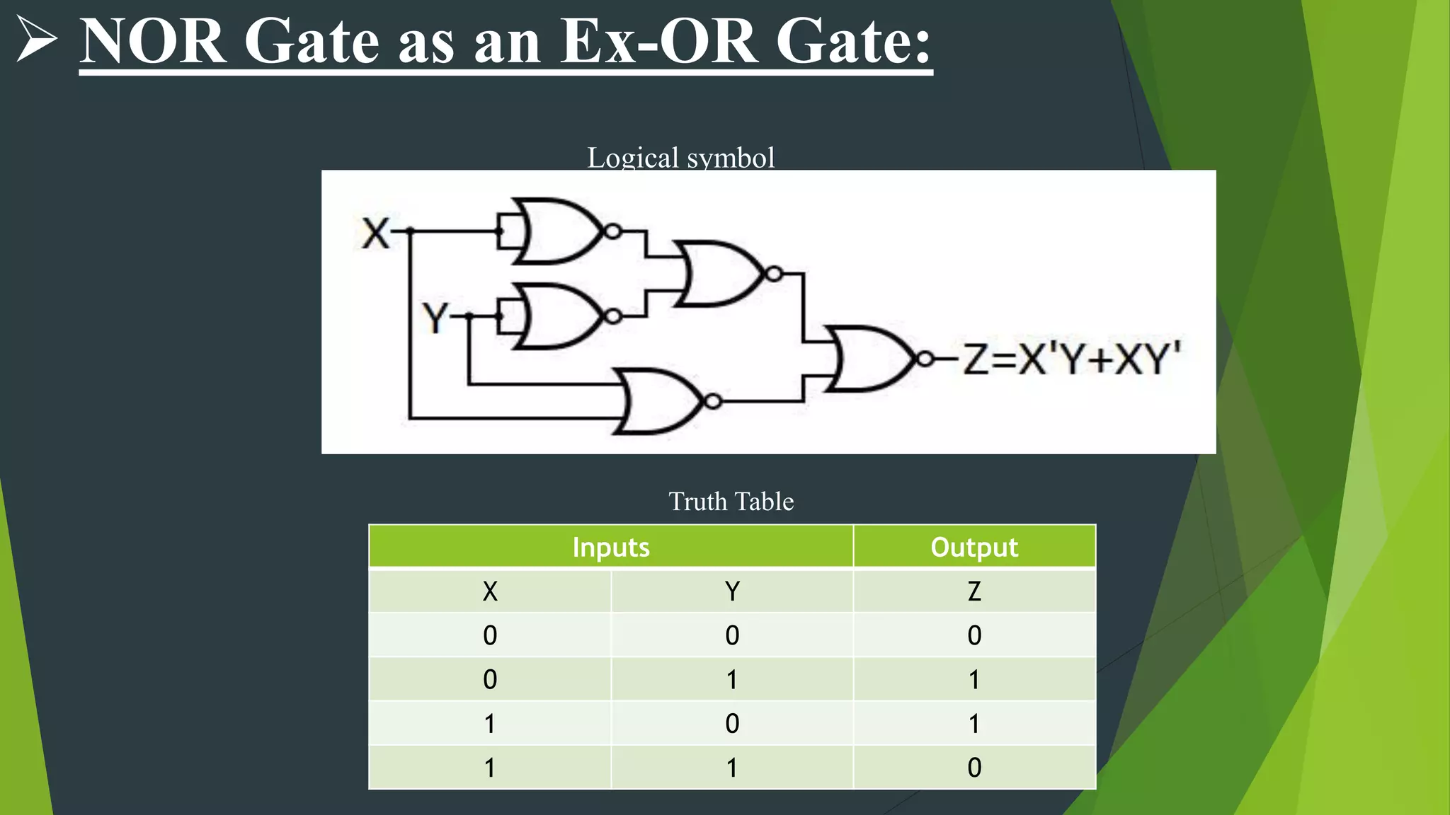
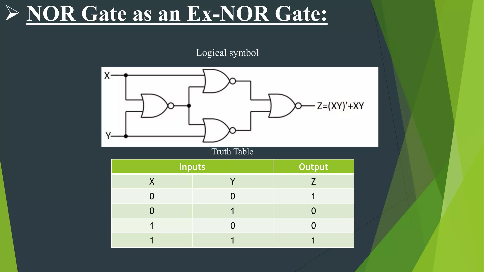


The document is a comprehensive overview of digital electronics, focusing on various types of logic gates including AND, OR, NOT, NAND, NOR, exclusive-OR, and exclusive-NOR gates. Each gate is explained in terms of its function, truth table, and logical expressions. Additionally, it discusses the NAND and NOR gates as universal gates capable of performing the functions of other gate types.


![De Morgan Theorem B[1]](https://cdn.slidesharecdn.com/ss_thumbnails/demorgantheoremb1-090930110355-phpapp01-thumbnail.jpg?width=640&height=640&fit=bounds)