Downloaded 126 times
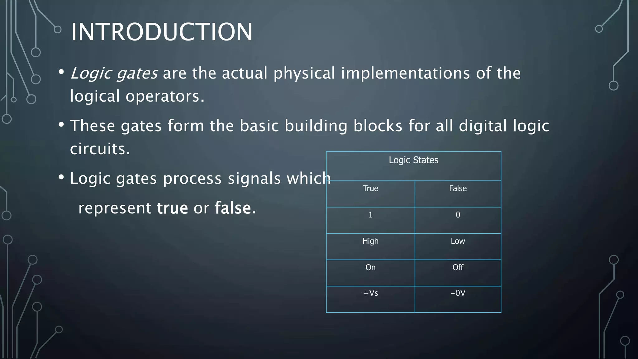
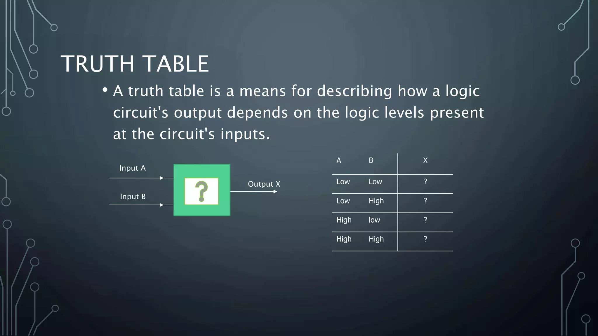
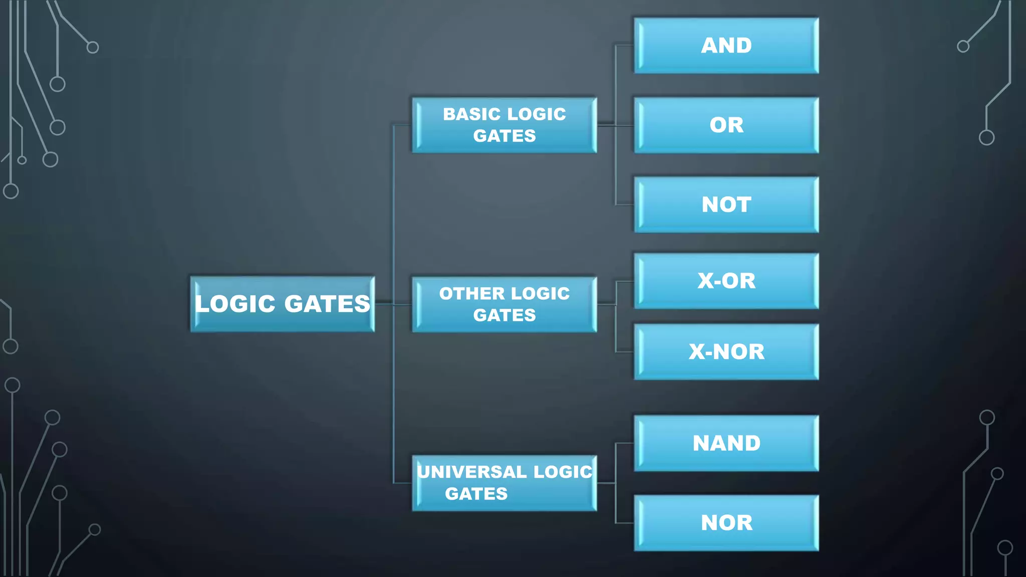
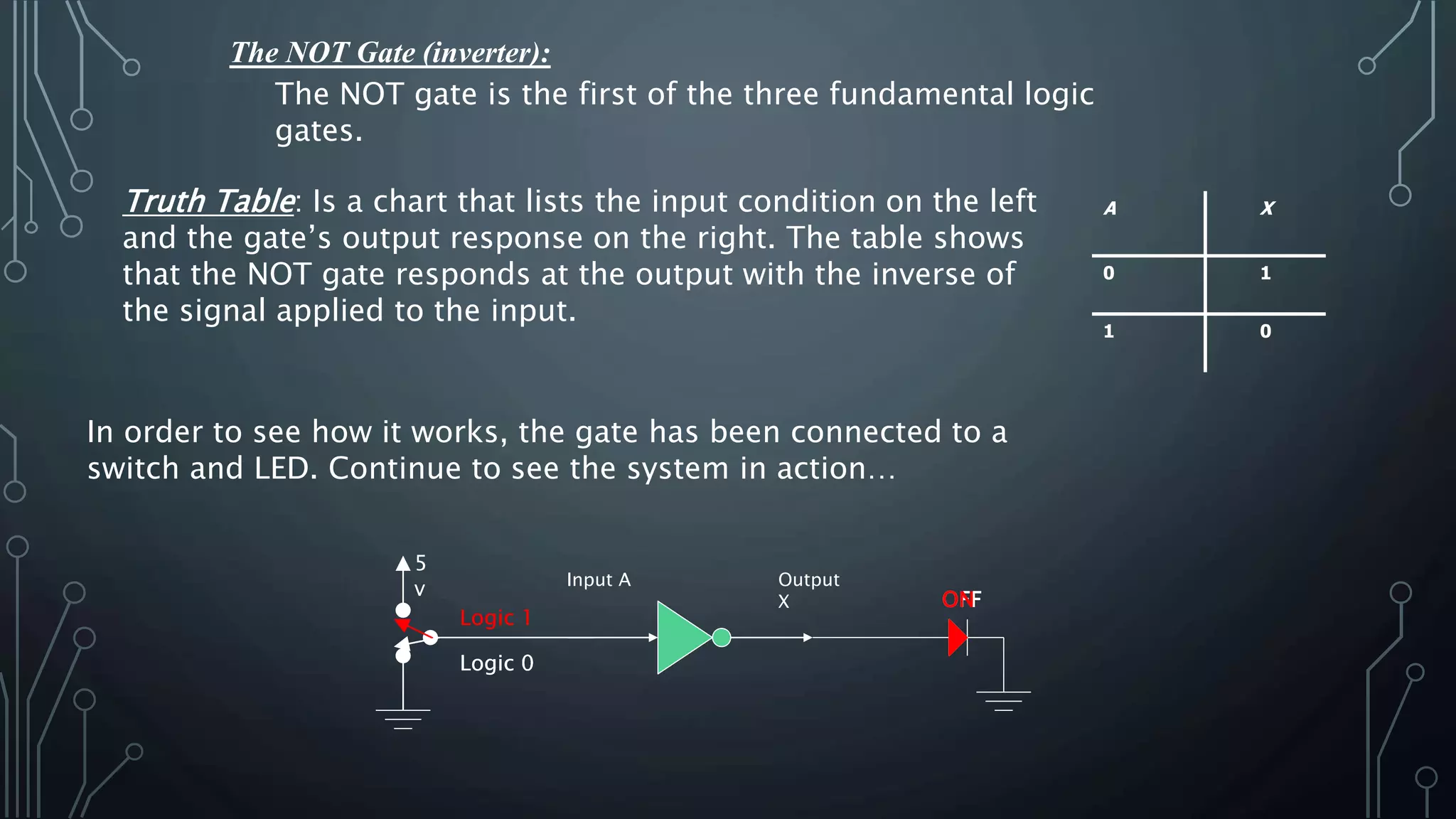
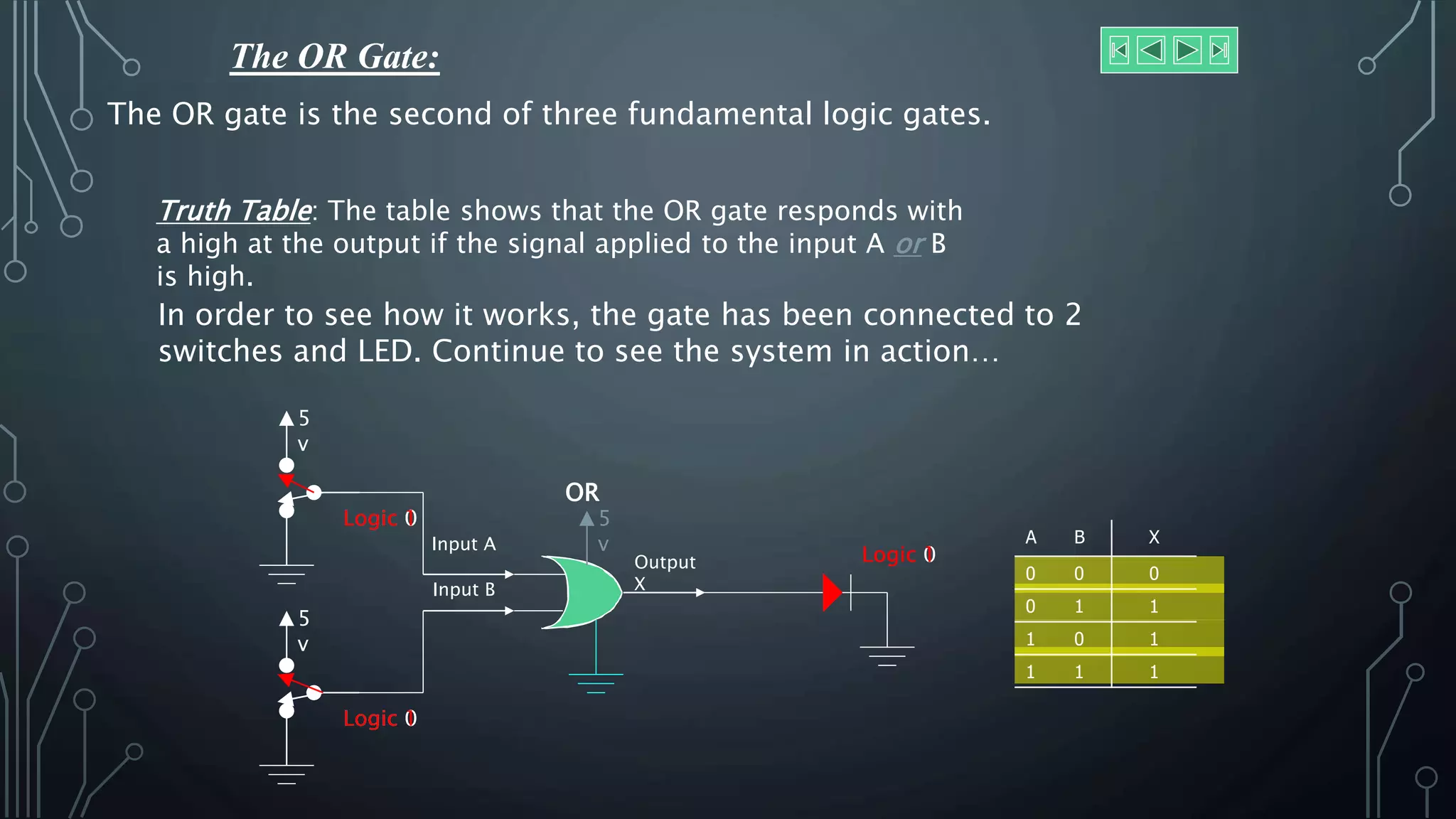
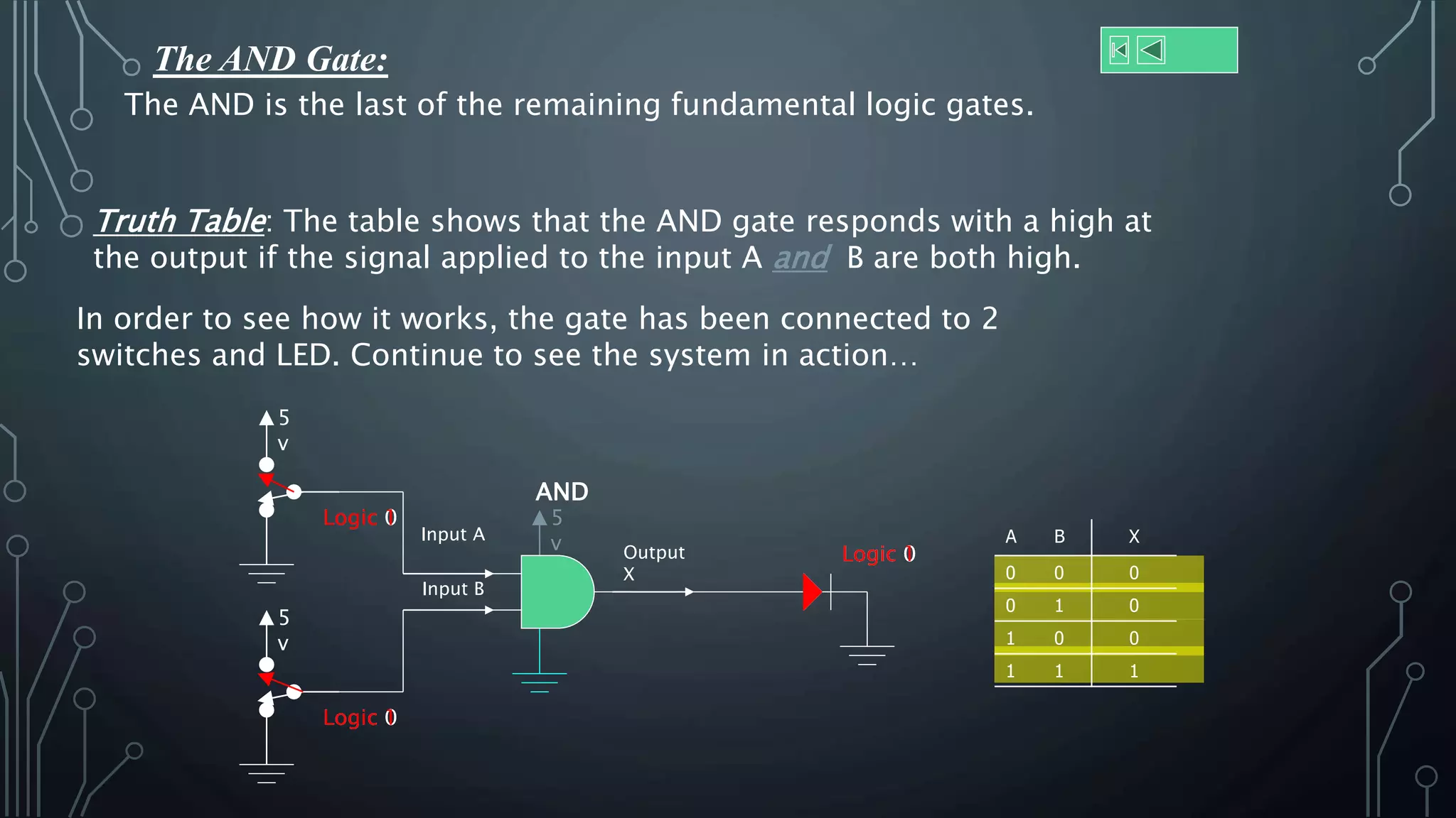
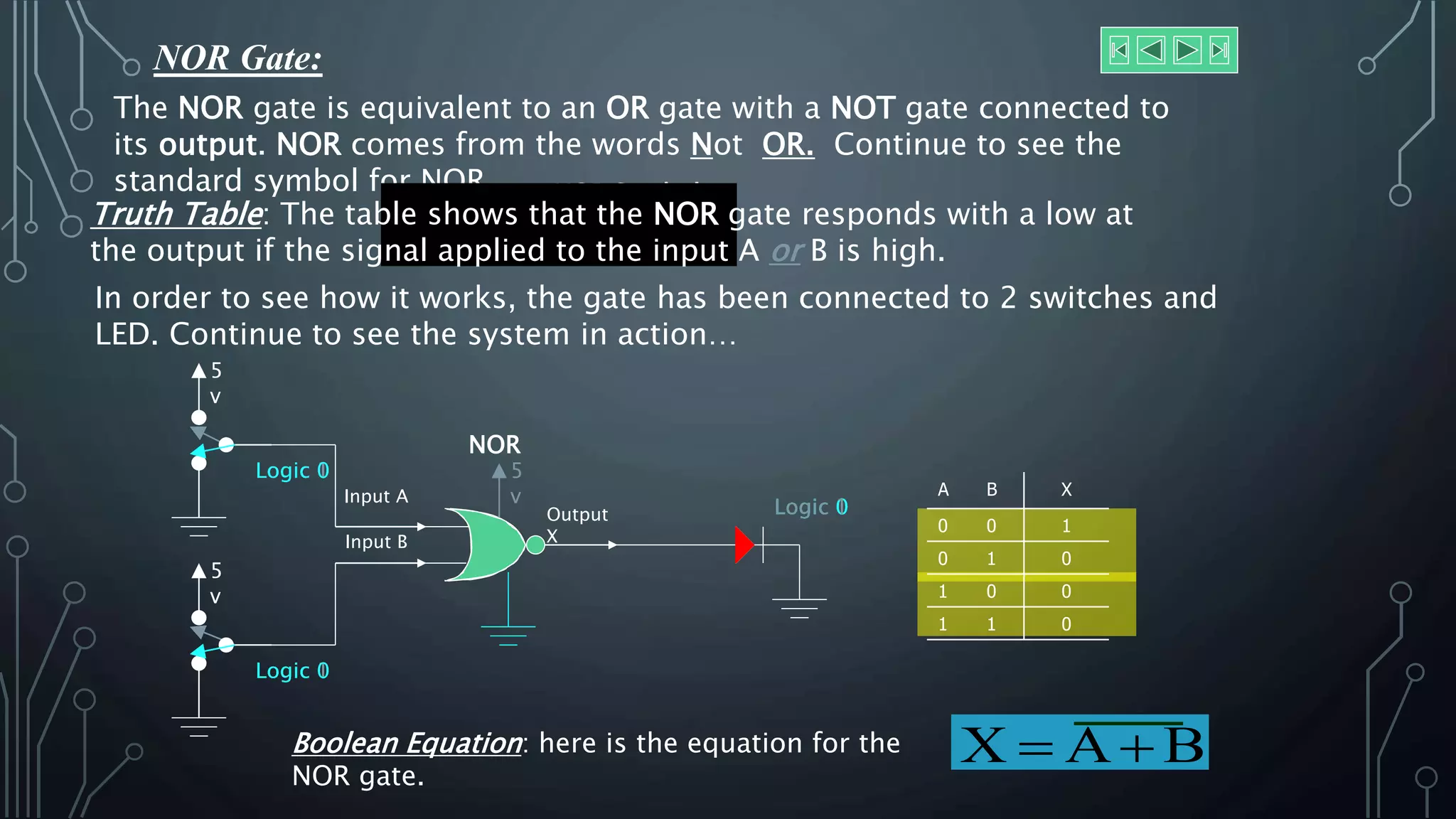
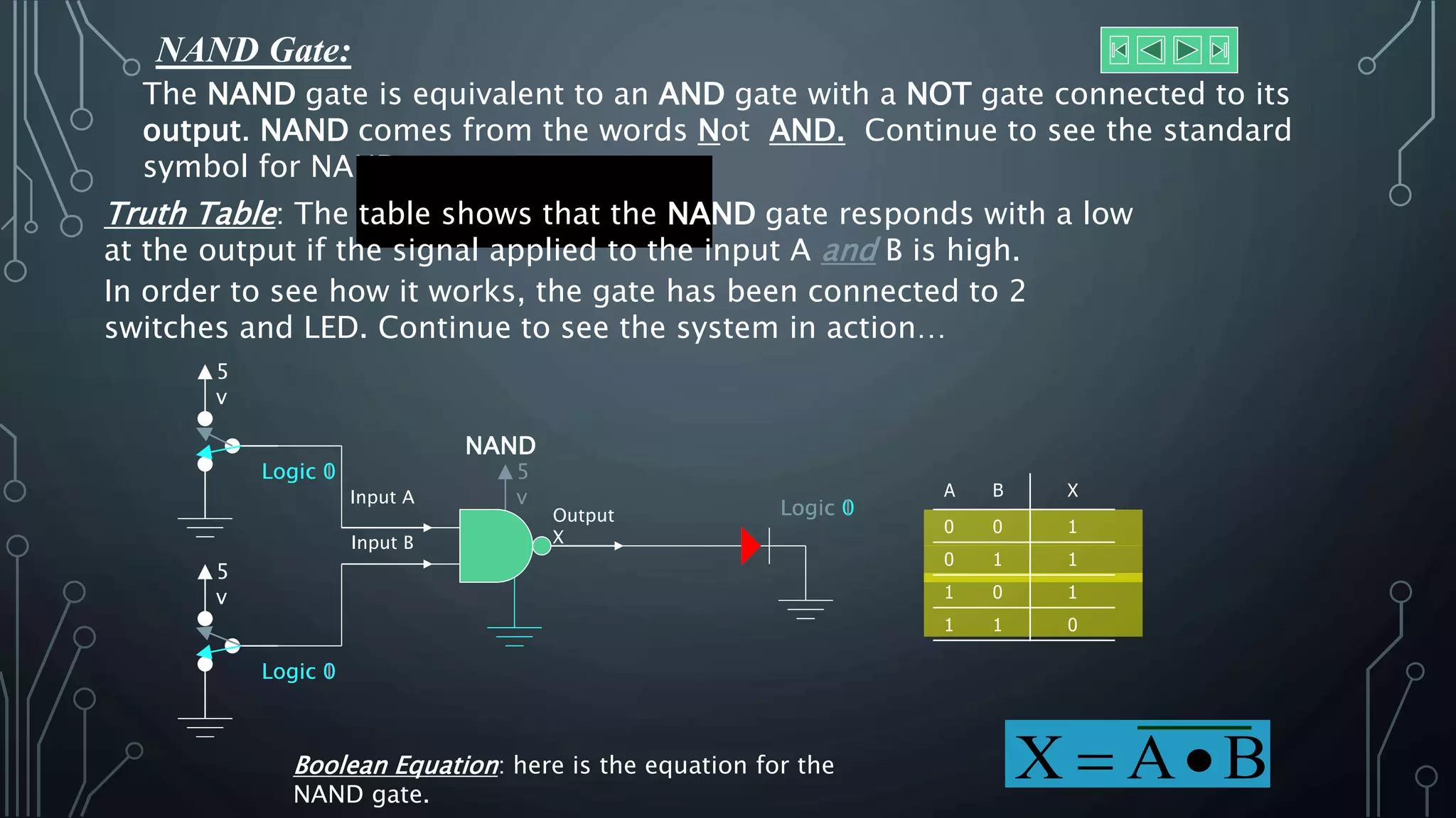
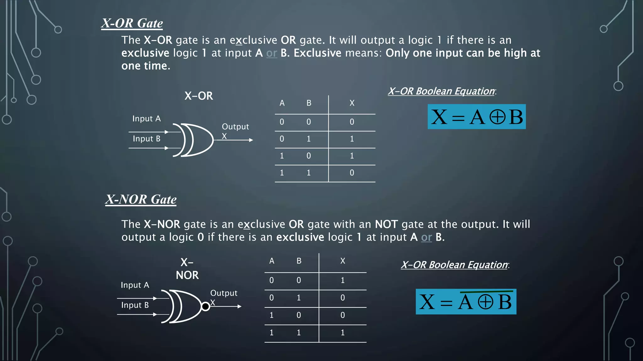


The document provides an overview of logic gates, which are fundamental components in digital circuits that implement logical operations on binary signals. It covers the basic gates such as AND, OR, NOT, as well as their respective truth tables, operational principles, and examples of their configuration using switches and LEDs. Additionally, it discusses other gates like NOR, NAND, XOR, and XNOR, explaining their functions through truth tables and Boolean equations.


![Coded Agents – with UiPath SDK + LangGraph [Virtual Hands-on Workshop]](https://cdn.slidesharecdn.com/ss_thumbnails/codedagentsdeck-251215155422-5497c599-thumbnail.jpg?width=640&height=640&fit=bounds)


![Vibe Coding vs. Spec-Driven Development [Free Meetup]](https://cdn.slidesharecdn.com/ss_thumbnails/vibecodingvsspecdrivendevelopment-251209105622-43f455e7-thumbnail.jpg?width=640&height=640&fit=bounds)


