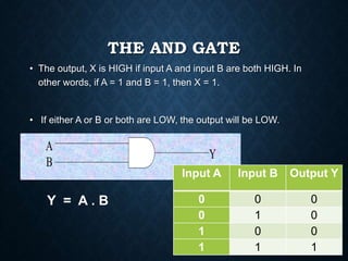
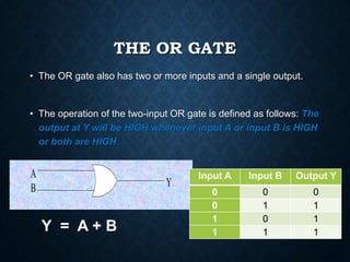
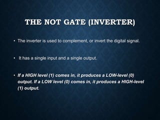
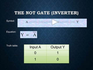
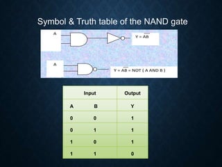
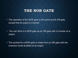
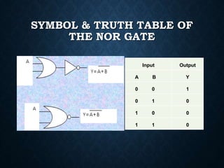
1. This document defines and explains the basic logic gates: NOT, AND, OR, NAND, NOR, EX-OR, and EX-NOR. It provides the logic symbol, truth table, and explains the output of each gate based on the input(s).
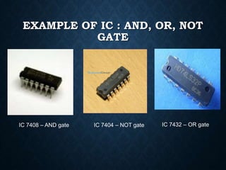
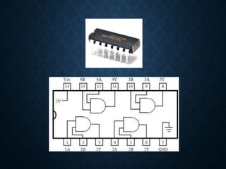
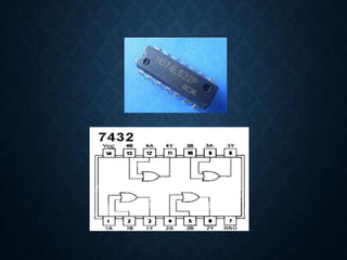
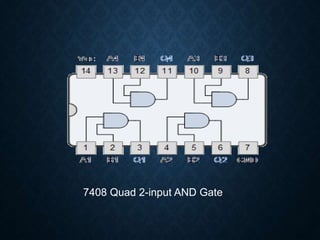
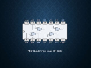
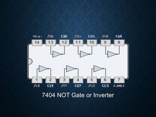
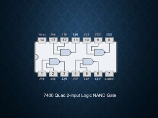
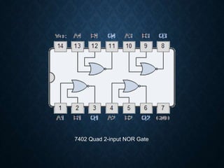
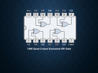
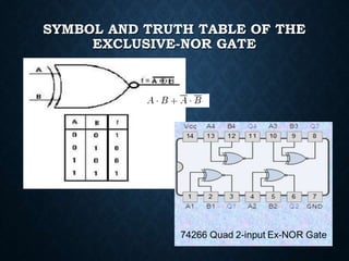
2. Examples of integrated circuits (ICs) that implement these basic logic gates are provided, such as the 7408 IC for AND gates and the 7404 IC for NOT gates.
3. At the end, there are exercises to develop truth tables for 3-input EX-OR and EX-NOR gates.


![067 [BEEE].pptx](https://cdn.slidesharecdn.com/ss_thumbnails/067beee-230703042004-87a7ab4e-thumbnail.jpg?width=640&height=640&fit=bounds)
![067 [BEEE].pptx](https://cdn.slidesharecdn.com/ss_thumbnails/067beee-230703041908-0bac0dfc-thumbnail.jpg?width=640&height=640&fit=bounds)


