Downloaded 324 times


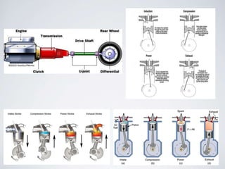
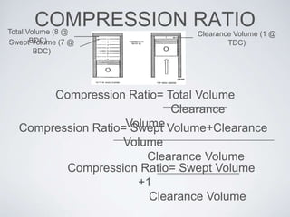


The document provides an in-depth overview of internal combustion engines, specifically focusing on the four-stroke engine, its components, and their functions, including the engine block, crankshaft, pistons, spark plugs, fuel injectors, and camshaft. It explains processes like intake, compression, power, and exhaust strokes, as well as concepts like compression ratio, torque, and power measurement. Additionally, it contrasts different camshaft designs (OHV, SOHC, DOHC) and methods of forced induction (turbochargers and superchargers), elaborating on their advantages and characteristics.


![[English Version]Maker-Ray Product Brochure V3 .pdf](https://cdn.slidesharecdn.com/ss_thumbnails/englishversionmaker-rayproductbrochurev3-260113094444-0156dbdc-thumbnail.jpg?width=640&height=640&fit=bounds)


![Alan Lucas - [Template] [Template] [Template] ScienceFairProjectTemplate.pptx](https://cdn.slidesharecdn.com/ss_thumbnails/alanlucas-templatetemplatetemplatesciencefairprojecttemplate-260106222421-b6ad9ab7-thumbnail.jpg?width=640&height=640&fit=bounds)
