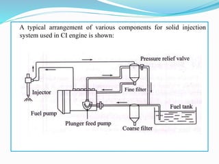
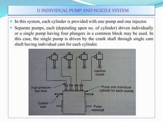
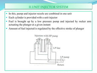
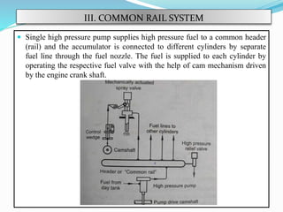
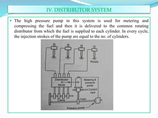
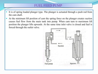
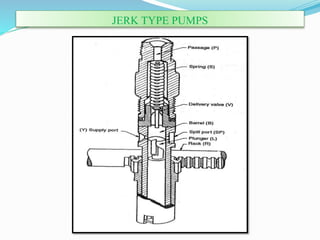
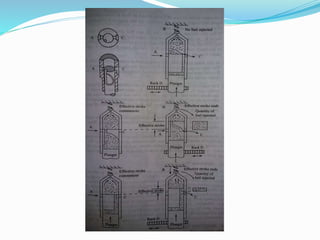
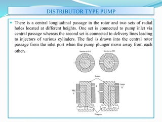
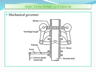
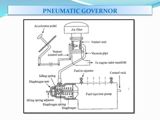
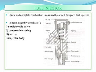
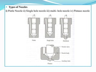
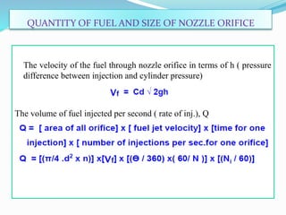
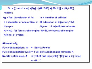
The document discusses mechanical fuel injection systems for diesel engines. It describes the key components of such a system including the fuel tank, fuel feed pump, injection pump, injectors, and filters. It then covers four main types of injection systems - individual pump and nozzle, unit injector, common rail, and distributor systems. For each system, it explains the basic configuration and operation. The document also discusses injection pumps, governors, injectors, nozzles, spray formation, and equations for determining fuel velocity and injection rate. In summary, it provides an overview of the components, classification, and functioning of mechanical fuel injection systems for diesel engines.
The common rail fuel injection system is finding increasing use engines as it has the potential to drastically cut emissions and fuel consumption. This system provides control of many important parameters linked to the injection system. It has a wide range of applications, From small to heavy-duty engines.
This presentation include the information about the different types of superchargers, advantages & disadvantages of superchargers and turbochargers. One case study of variable geometry turbocharger is included with literature review.
This slides are about inline injection pump and calibration of the pumps .The working of the pump is described in simple words and with examples of daily usable devices.
ICE_Handout(5) for CI fuel injection.pdf20007134009
FUEL INJECTION SYSTEM FOR CI ENGINES
The function of a fuel injection system is to meter the appropriate quantity of fuel for the given
engine speed and load to each cylinder, each cycle, and inject that fuel at the appropriate time in the
cycle at the desired rate with the spray configuration required for the particular combustion
chamber employed. It is important that injection begin and end cleanly, and avoid any secondary
injections. To accomplish this function, fuel is usually drawn from the fuel tank by a supply pump,
and forced through a filter to the injection pump. The injection pump sends fuel under pressure to
the nozzle pipes which carry fuel to the injector nozzles located in each cylinder head. Excess fuel
goes back to the fuel tank. CI engines are operated unthrottled, with engine speed and power
controlled by the amount of fuel injected during each cycle. This allows for high volumetric
efficiency at all speeds, with the intake system designed for very little flow restriction of the
incoming air.
FUNCTIONAL REQUIREMENTS OF AN INJECTION SYSTEM
For a proper running and good performance of the engine, the following requirements must be met
by the injection system:
• Accurate metering of the fuel injected per cycle. Metering errors may cause drastic variation
from the desired output. The quantity of the fuel metered should vary to meet changing speed
and load requirements of the engine.
• Correct timing of the injection of the fuel in the cycle so that maximum power is obtained.
• Proper control of rate of injection so that the desired heat-release pattern is achieved during
combustion.
• Proper atomization of fuel into very fine droplets.
• Proper spray pattern to ensure rapid mixing of fuel and air.
• Uniform distribution of fuel droplets throughout the combustion chamber
• To supply equal quantities of metered fuel to all cylinders in case of multi-cylinder engines.
• No lag during beginning and end of injection i.e., to eliminate dribbling of fuel droplets into the
cylinder.
TYPES OF INJECTION SYSTEMS
There are basically two types of injection systems: Air injection system and solid injection system.
Air Injection System: In this system, fuel is forced into the cylinder by means of compressed air.
This system is little used nowadays, because it requires a bulky multi-stage air compressor. This
causes an increase in engine weight and reduces the brake power output further. One advantage that
is claimed for the air injection system is good mixing of fuel with the air resulting in higher mean
effective pressure. Another advantage is its ability to utilize fuels of high viscosity which are less
expensive than those used by the engines with solid injection systems. These advantages are off-set
by the requirement of a multistage compressor thereby making the air-injection system obsolete.
Solid Injection System: In this system the liquid fuel is injected directly in.
Unit Injector System: In this syst
ENGINE AUXILIARY SYSTEMS
Electronically controlled gasoline injection system for SI engines, Electronically controlled diesel injection system (Unit injector system, Rotary distributor type and common rail direct injection system), Electronic ignition system (Transistorized coil ignition system, capacitive discharge ignition system), Turbo chargers (WGT, VGT), Engine emission control by three way catalytic converter system, Emission norms (Euro and BS).
Electronically controlled gasoline injection system for SI engines – Electronically controlled diesel injection system – unit injector system, rotary distributor type and common rail direct injection system – Electronic ignition system: transistorized coil ignition system, capacitive discharge ignition system – Turbochargers - waste gate turbocharger, variable geometry turbocharger – engine emission control by three way catalytic converter system – emission norms (Euro, BS).
UNIT-II-ENGINE AUXILIARY SYSTEMS &TURBOCHARGERDineshKumar4165
Electronically controlled gasoline injection system for SI engines, Electronically controlled diesel injection system, Unit injector system, Rotary distributor type and common rail direct injection system, Electronic ignition system - Transistorized coil ignition system, capacitive discharge ignition system, Turbo chargers -Waste Gate Turbocharger, Variable Geomentry Turbocharger, Engine emission control by three way catalytic converter system, Emission norms (Euro and BS).
Types of Fuel Injection systems in Spark Ignition and Compression Ignition En...Hassan Raza
This presentation was prepared by Mechanical Engineers during their final year in their Internal Combustion Engine program offered at University of Engineering and Technology Lahore.
Democratizing Fuzzing at Scale by Abhishek Aryaabh.arya
Presented at NUS: Fuzzing and Software Security Summer School 2024
This keynote talks about the democratization of fuzzing at scale, highlighting the collaboration between open source communities, academia, and industry to advance the field of fuzzing. It delves into the history of fuzzing, the development of scalable fuzzing platforms, and the empowerment of community-driven research. The talk will further discuss recent advancements leveraging AI/ML and offer insights into the future evolution of the fuzzing landscape.
Quality defects in TMT Bars, Possible causes and Potential Solutions.PrashantGoswami42
Maintaining high-quality standards in the production of TMT bars is crucial for ensuring structural integrity in construction. Addressing common defects through careful monitoring, standardized processes, and advanced technology can significantly improve the quality of TMT bars. Continuous training and adherence to quality control measures will also play a pivotal role in minimizing these defects.
Hybrid optimization of pumped hydro system and solar- Engr. Abdul-Azeez.pdffxintegritypublishin
Advancements in technology unveil a myriad of electrical and electronic breakthroughs geared towards efficiently harnessing limited resources to meet human energy demands. The optimization of hybrid solar PV panels and pumped hydro energy supply systems plays a pivotal role in utilizing natural resources effectively. This initiative not only benefits humanity but also fosters environmental sustainability. The study investigated the design optimization of these hybrid systems, focusing on understanding solar radiation patterns, identifying geographical influences on solar radiation, formulating a mathematical model for system optimization, and determining the optimal configuration of PV panels and pumped hydro storage. Through a comparative analysis approach and eight weeks of data collection, the study addressed key research questions related to solar radiation patterns and optimal system design. The findings highlighted regions with heightened solar radiation levels, showcasing substantial potential for power generation and emphasizing the system's efficiency. Optimizing system design significantly boosted power generation, promoted renewable energy utilization, and enhanced energy storage capacity. The study underscored the benefits of optimizing hybrid solar PV panels and pumped hydro energy supply systems for sustainable energy usage. Optimizing the design of solar PV panels and pumped hydro energy supply systems as examined across diverse climatic conditions in a developing country, not only enhances power generation but also improves the integration of renewable energy sources and boosts energy storage capacities, particularly beneficial for less economically prosperous regions. Additionally, the study provides valuable insights for advancing energy research in economically viable areas. Recommendations included conducting site-specific assessments, utilizing advanced modeling tools, implementing regular maintenance protocols, and enhancing communication among system components.
Immunizing Image Classifiers Against Localized Adversary Attacksgerogepatton
This paper addresses the vulnerability of deep learning models, particularly convolutional neural networks
(CNN)s, to adversarial attacks and presents a proactive training technique designed to counter them. We
introduce a novel volumization algorithm, which transforms 2D images into 3D volumetric representations.
When combined with 3D convolution and deep curriculum learning optimization (CLO), itsignificantly improves
the immunity of models against localized universal attacks by up to 40%. We evaluate our proposed approach
using contemporary CNN architectures and the modified Canadian Institute for Advanced Research (CIFAR-10
and CIFAR-100) and ImageNet Large Scale Visual Recognition Challenge (ILSVRC12) datasets, showcasing
accuracy improvements over previous techniques. The results indicate that the combination of the volumetric
input and curriculum learning holds significant promise for mitigating adversarial attacks without necessitating
adversary training.
Saudi Arabia stands as a titan in the global energy landscape, renowned for its abundant oil and gas resources. It's the largest exporter of petroleum and holds some of the world's most significant reserves. Let's delve into the top 10 oil and gas projects shaping Saudi Arabia's energy future in 2024.
CFD Simulation of By-pass Flow in a HRSG module by R&R Consult.pptxR&R Consult
CFD analysis is incredibly effective at solving mysteries and improving the performance of complex systems!
Here's a great example: At a large natural gas-fired power plant, where they use waste heat to generate steam and energy, they were puzzled that their boiler wasn't producing as much steam as expected.
R&R and Tetra Engineering Group Inc. were asked to solve the issue with reduced steam production.
An inspection had shown that a significant amount of hot flue gas was bypassing the boiler tubes, where the heat was supposed to be transferred.
R&R Consult conducted a CFD analysis, which revealed that 6.3% of the flue gas was bypassing the boiler tubes without transferring heat. The analysis also showed that the flue gas was instead being directed along the sides of the boiler and between the modules that were supposed to capture the heat. This was the cause of the reduced performance.
Based on our results, Tetra Engineering installed covering plates to reduce the bypass flow. This improved the boiler's performance and increased electricity production.
It is always satisfying when we can help solve complex challenges like this. Do your systems also need a check-up or optimization? Give us a call!
Work done in cooperation with James Malloy and David Moelling from Tetra Engineering.
More examples of our work https://www.r-r-consult.dk/en/cases-en/
Overview of the fundamental roles in Hydropower generation and the components involved in wider Electrical Engineering.
This paper presents the design and construction of hydroelectric dams from the hydrologist’s survey of the valley before construction, all aspects and involved disciplines, fluid dynamics, structural engineering, generation and mains frequency regulation to the very transmission of power through the network in the United Kingdom.
Author: Robbie Edward Sayers
Collaborators and co editors: Charlie Sims and Connor Healey.
(C) 2024 Robbie E. Sayers
Welcome to WIPAC Monthly the magazine brought to you by the LinkedIn Group Water Industry Process Automation & Control.
In this month's edition, along with this month's industry news to celebrate the 13 years since the group was created we have articles including
A case study of the used of Advanced Process Control at the Wastewater Treatment works at Lleida in Spain
A look back on an article on smart wastewater networks in order to see how the industry has measured up in the interim around the adoption of Digital Transformation in the Water Industry.
Forklift Classes Overview by Intella PartsIntella Parts
Discover the different forklift classes and their specific applications. Learn how to choose the right forklift for your needs to ensure safety, efficiency, and compliance in your operations.
For more technical information, visit our website https://intellaparts.com
TECHNICAL TRAINING MANUAL GENERAL FAMILIARIZATION COURSEDuvanRamosGarzon1
AIRCRAFT GENERAL
The Single Aisle is the most advanced family aircraft in service today, with fly-by-wire flight controls.
The A318, A319, A320 and A321 are twin-engine subsonic medium range aircraft.
The family offers a choice of engines
3. INTRODUCTION
Fuel-Injection System is vital to the working and performance of CI
engine.
The injection system is required for initiating and controlling the
combustion process.
In case of carburetion fuel is atomized by processes relying on the air
speed greater than fuel speed at the fuel nozzle, whereas in fuel injection
the fuel speed at the point of delivery is greater than the air speed to
atomize the fuel.
Fuel is injected into combustion chamber towards the end of
compression. It is atomized as it enters under high velocity and the
droplets get vaporized to form a fuel-air mixture. Due to continued heat
transfer from hot air to fuel, the fuel reaches to its self ignition
temperature to ignite spontaneously initiating combustion. Depending
upon the demand requirements the fuel injection system continues to
deliver the fuel during initial part of combustion.
4. FUNCTIONAL REQUIREMENTS OF AN INJECTION SYSTEM
For proper engine operation and satisfactory performance, the
following requirements must be met by the Fuel Injection (FI)
System :-
Accurate metering of fuel injected per cycle to meet changing
demand of speed & load
Precise timing of fuel injection in the cycle to ensure performance;
power, fuel economy, emissions
Proper control of rate of injection to achieve desired heat release
during combustion without knocking
Proper atomization of fuel into fine droplets
Proper spray pattern to ensure rapid mixing of fuel & air
Uniform distribution of fuel droplets throughout the combustion
chamber
To supply equal quantities of metered fuel to all cylinders in case
of multi cylinder engines
No lag during beginning and end of injection to eliminate
dribbling of fuel droplets into the cylinder
5. CLASSIFICATION OF INJECTION SYSTEM
Two types:-
Air Injection system and Solid Injection system
Air Injection system : Fuel is forced by means of compressed
air. Good mixing with higher mep. It requires compressor.
Ability to use high viscosity fuel. Not much in use.
Solid Injection system : Liquid fuel is injected directly into
combustion chamber. Solid injection systems can be classified
into ;
i) Individual pump and nozzle system
ii) Unit Injector system
iii) Common rail system
iv) Distributor system
6. COMPONENTS
All the FI systems comprise of following components:
Fuel tank
Fuel feed pump to supply fuel from fuel tank to FI system
Injection pump to meter and pressurize the fuel for injection
Governor to ensure that the amount of fuel injected is in
accordance with variation of load
Injector to take the fuel from the pump and distribute it in the
combustion chamber by atomizing it into fine droplets
Fuel filters to prevent dust and abrasive particles from entering
the pump & injectors to reduce wear & tear of components
7. A typical arrangement of various components for solid injection
system used in CI engine is shown:
8. I) INDIVIDUAL PUMP AND NOZZLE SYSTEM
In this system, each cylinder is provided with one pump and one injector.
Separate pumps, each (depending upon no. of cylinder) driven individually
or a single pump having four plungers in a common block may be used. In
this case, the single pump is driven by the crank shaft through single cam
shaft having individual cam for each cylinder.
9. II.UNIT INJECTOR SYSTEM
In this, pump and injector nozzle are combined in one unit
Each cylinder is provided with a unit injector
Fuel is brought up by a low pressure pump and injected by rocker arm
actuating the plunger at a given instant
Amount of fuel injected is regulated by the effective stroke of plunger
10. III. COMMON RAIL SYSTEM
Single high pressure pump supplies high pressure fuel to a common header
(rail) and the accumulator is connected to different cylinders by separate
fuel line through the fuel nozzle. The fuel is supplied to each cylinder by
operating the respective fuel valve with the help of cam mechanism driven
by the engine crank shaft.
11. IV. DISTRIBUTOR SYSTEM
The high pressure pump in this system is used for metering and
compressing the fuel and then it is delivered to the common rotating
distributor from which the fuel is supplied to each cylinder. In every cycle,
the injection strokes of the pump are equal to the no. of cylinders.
12. FUEL FEED PUMP
It is of spring loaded plunger type. The plunger is actuated through a push rod from
the cam shaft.
At the minimum lift position of cam the spring force on the plunger creates suction
causes fuel flow from the main tank into pump. When cam turn to maximum lift
position the plunger lifts upwards. At the same time inlet valve is closed and fuel is
forced through the outlet valve.
13. INJECTION PUMP
The main objective of the fuel- injection pump is to deliver
accurately metered quantity of fuel under high pressure at the
correct instant to the injector fitted on cylinder.
Injection pumps are of two types;
- Jerk Type Pumps
- Distributor Type Pumps
Jerks Type Pumps: It consists of a reciprocating plunger
inside a barrel. The plunger is driven by a cam.
Distributor Type Pumps: This pump has only a single
pumping element and the fuel is distributed to each cylinder by
means of a rotor .
15. ACTUAL METHOD OF CONTROLLING QUANTITY
OF FUEL INJECTED IN A C.I ENGINE
16.
17. DISTRIBUTOR TYPE PUMP
There is a central longitudinal passage in the rotor and two sets of radial
holes located at different heights. One set is connected to pump inlet via
central passage whereas the second set is connected to delivery lines leading
to injectors of various cylinders. The fuel is drawn into the central rotor
passage from the inlet port when the pump plunger move away from each
other.
20. FUEL INJECTOR
Quick and complete combustion is ensured by a well designed fuel injector.
Injector assembly consists of ;
i) nozzle/needle valve
ii) compression spring
iii) nozzle
iv) injector body
21. NOZZLE
It is that part of an injector through which the liquid fuel is
sprayed into combustion chamber.
Nozzle should fulfill the following functions:
i) Atomization
ii) Distribution of fuel
iii) Prevention of impingement on walls: decomposition
v) Mixing : in case of non-turbulent type of combustion chamber
22. Types of Nozzles
i) Pintle Nozzle ii) Single hole nozzle iii) multi- hole nozzle iv) Pintaux nozzle
23. SPRAY FORMATION
At the start of injection the pressure difference across the
orifice is low and single droplets are formed.
As pressure difference increases following occurs :
A stream of fuel emerges
Stream encounter aerodynamic resistance from dense air( 12 to
14 times ambient pressure ) and breaks into a spray at the
break-up distance
With further increase in pressure the break- up distance
decreases and the cone angle increases until apex of the cone
practically coincides with the orifice
Successive phases of spray formation is given in the figure.
24.
25. At the exit of the orifice the fuel jet velocity, Vf , is of the order
of 400 m/s. It is given by the following equation,
Where,
Cd = coefficient of discharge for the orifice
pinj = fuel pressure at the inlet to injector, N/m2
pcyl = pressure of charge inside the cylinder, N/m2
= density of fuel, kg/ m
3
26. QUANTITY OF FUEL AND SIZE OF NOZZLE ORIFICE
The velocity of the fuel through nozzle orifice in terms of h ( pressure
difference between injection and cylinder pressure)
The volume of fuel injected per second ( rate of inj.), Q