Module 3
Fundamentals ofIC Engines:
Review of Internal Combustion Engines, 2-Strokes and 4-Strokes engines,
Components and working principles, Application of IC Engines in Power Generation,
Agriculture, Marine and Aircraft Propulsion, Automobile.
ENGINE / HEAT ENGINE:
Heat engine : It can be defined as any machine or a device that converts chemical
energy of fuel into thermal/heat energy and this heat energy is further converted into
mechanical work output.
Examples of Heat engines include:
i. Steam engine,
ii. Diesel engine, and
iii. Gasoline (petrol) engine.
On the basis of how thermal energy is being delivered to working fluid of the heat
engine, heat engine can be classified as an
1. Internal Combustion Engine and
2. External Combustion Engine.
2.
• An ICEngine Is a heat engine which converts heat energy released by the
combustion of fuel inside the engine cylinder in to useful mechanical work.
• IC Engines are considered as Universal prime mover because:
High efficiency
Light Weight
Compactness
Ease to start
Adaptability
Suitable for mobile applications
Lower initial cost
Internal Combustion Engines (IC Engines)
3.
I C enginescan be classified based on:
1. Thermodynamic cycle:
i. Otto Cycle Engine
ii. Diesel Cycle Engine
iii. Dual Combustion Cycle Engine
2. Type of fuel used:
i. Petrol Engine
ii. Diesel Engine
iii. Gas Engine
iv. Bi Fuel Engine
3. No. of Strokes:
i. Two Stroke Engine
ii. Four Stroke Engine
4. Method of Ignition:
i. Spark Ignition Engine (SI Engine)
ii. Compression Ignition Engine
(CI Engine)
5. No. of Cylinders:
i. Single Cylinder Engine
ii. Multi Cylinder Engine
6. Orientation of Cylinders:
i. Horizontal Engine
ii. Vertical Engine
iii. V- Engine
iv. Opposed Cylinder Engine
v. Radial Engine
7. Method of cooling:
i. Air cooled Engine
ii. Liquid cooled Engine
Internal Combustion Engines (IC Engines)
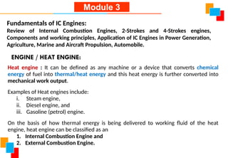
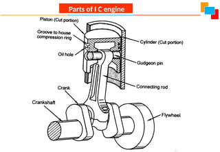
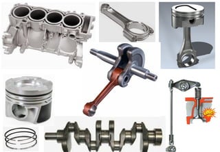
1. Cylinder
Thecylinder is made up of steel or aluminum alloys.
In this Piston reciprocates to develop power.
It will withstand high pressure and temperature.
2. Cylinder Head
Cylinder Head is fitted at the top of the cylinder.
It is made up of steel or aluminum alloys.
A copper or asbestos gasket is provided in between the
cylinder and the cylinder head to make it airtight.
3. Piston
It is made of aluminum alloys.
The main function is to transmit force exerted by burning of charge to connecting rod.
4. Piston Rings
These are circular rings made up of special steel alloys.
These are housed in circumferential grooves of the piston.
Two sets of rings are provided, with an upper ring (compression ring) to prevent leakage
of burnt gases into the lower portion, while lower ring (oil ring) to prevent leakage of oil
into the Engine Cylinder.
They retain elastic properties even at a higher temperature.
The rings are provided with an airtight seal.
Parts of I C engine
7.
5. Valves
Theseare provided on the cylinder head.
Inlet valve is used to take the fresh mixture into the cylinder.
The exhaust valve is used to expel burnt gases from the cylinder.
6. Connecting Rod
It is a link between the piston and the crankshaft.
The function of Connecting Rod is to transmit the power from piston to crankshaft.
7. Crankshaft
It is made of special steel alloys.
The function of the crankshaft is to convert the reciprocating motion of a piston into
rotary motion with the help of connecting rod.
8. Crankcase
The crankcase is made of cast iron.
It holds the cylinder and crankshaft of an engine.
It also serves as a sump (storing place) for lubricating oil.
9. Flywheel
It is a big solid wheel mounted on a crankshaft of an IC Engine.
The main function of the flywheel is to maintain speed constant.
It stores excess energy during power and gives out during the compression stroke.
Parts of I C engine
10.
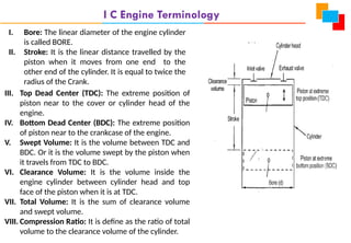
I C EngineTerminology
I. Bore: The linear diameter of the engine cylinder
is called BORE.
II. Stroke: It is the linear distance travelled by the
piston when it moves from one end to the
other end of the cylinder. It is equal to twice the
radius of the Crank.
III. Top Dead Center (TDC): The extreme position of
piston near to the cover or cylinder head of the
engine.
IV. Bottom Dead Center (BDC): The extreme position
of piston near to the crankcase of the engine.
V. Swept Volume: It is the volume between TDC and
BDC. Or it is the volume swept by the piston when
it travels from TDC to BDC.
VI. Clearance Volume: It is the volume inside the
engine cylinder between cylinder head and top
face of the piston when it is at TDC.
VII. Total Volume: It is the sum of clearance volume
and swept volume.
VIII. Compression Ratio: It is define as the ratio of total
volume to the clearance volume of the cylinder.
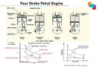
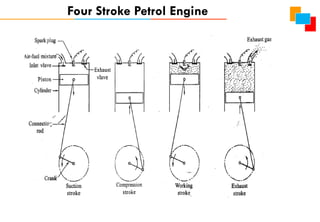
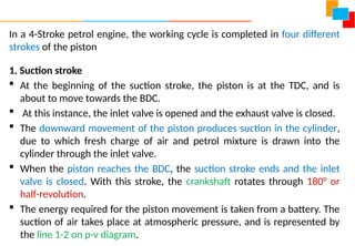
In a 4-Strokepetrol engine, the working cycle is completed in four different
strokes of the piston
1. Suction stroke
At the beginning of the suction stroke, the piston is at the TDC, and is
about to move towards the BDC.
At this instance, the inlet valve is opened and the exhaust valve is closed.
The downward movement of the piston produces suction in the cylinder,
due to which fresh charge of air and petrol mixture is drawn into the
cylinder through the inlet valve.
When the piston reaches the BDC, the suction stroke ends and the inlet
valve is closed. With this stroke, the crankshaft rotates through 180° or
half-revolution.
The energy required for the piston movement is taken from a battery. The
suction of air takes place at atmospheric pressure, and is represented by
the line 1-2 on p-v diagram.
15.
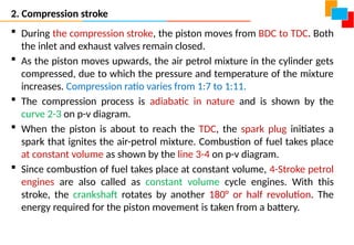
2. Compression stroke
During the compression stroke, the piston moves from BDC to TDC. Both
the inlet and exhaust valves remain closed.
As the piston moves upwards, the air petrol mixture in the cylinder gets
compressed, due to which the pressure and temperature of the mixture
increases. Compression ratio varies from 1:7 to 1:11.
The compression process is adiabatic in nature and is shown by the
curve 2-3 on p-v diagram.
When the piston is about to reach the TDC, the spark plug initiates a
spark that ignites the air-petrol mixture. Combustion of fuel takes place
at constant volume as shown by the line 3-4 on p-v diagram.
Since combustion of fuel takes place at constant volume, 4-Stroke petrol
engines are also called as constant volume cycle engines. With this
stroke, the crankshaft rotates by another 180° or half revolution. The
energy required for the piston movement is taken from a battery.
16.
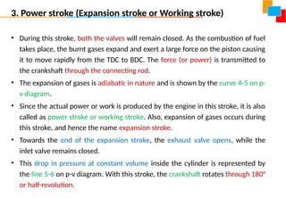
3. Power stroke(Expansion stroke or Working stroke)
• During this stroke, both the valves will remain closed. As the combustion of fuel
takes place, the burnt gases expand and exert a large force on the piston causing
it to move rapidly from the TDC to BDC. The force (or power) is transmitted to
the crankshaft through the connecting rod.
• The expansion of gases is adiabatic in nature and is shown by the curve 4-5 on p-
v diagram.
• Since the actual power or work is produced by the engine in this stroke, it is also
called as power stroke or working stroke. Also, expansion of gases occurs during
this stroke, and hence the name expansion stroke.
• Towards the end of the expansion stroke, the exhaust valve opens, while the
inlet valve remains closed.
• This drop in pressure at constant volume inside the cylinder is represented by
the line 5-6 on p-v diagram. With this stroke, the crankshaft rotates through 180°
or half-revolution.
17.
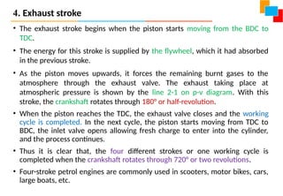
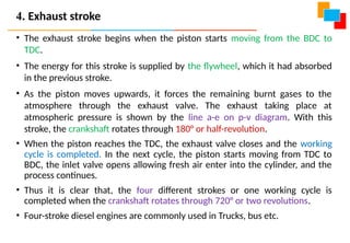
4. Exhaust stroke
•The exhaust stroke begins when the piston starts moving from the BDC to
TDC.
• The energy for this stroke is supplied by the flywheel, which it had absorbed
in the previous stroke.
• As the piston moves upwards, it forces the remaining burnt gases to the
atmosphere through the exhaust valve. The exhaust taking place at
atmospheric pressure is shown by the line 2-1 on p-v diagram. With this
stroke, the crankshaft rotates through 180° or half-revolution.
• When the piston reaches the TDC, the exhaust valve closes and the working
cycle is completed. In the next cycle, the piston starts moving from TDC to
BDC, the inlet valve opens allowing fresh charge to enter into the cylinder,
and the process continues.
• Thus it is clear that, the four different strokes or one working cycle is
completed when the crankshaft rotates through 720° or two revolutions.
• Four-stroke petrol engines are commonly used in scooters, motor bikes, cars,
large boats, etc.
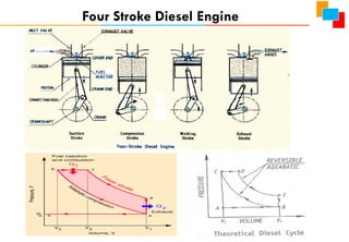
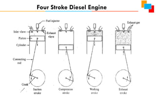
A 4-stroke dieselengine works on Diesel cycle. Hence it is also called
Diesel cycle engine. The working principle is similar to that of 4-stroke
petrol engine, except a fuel injector is used in place of spark plug, and only
air enters the cylinder during the suction stroke and gets compressed in
the compression stroke.
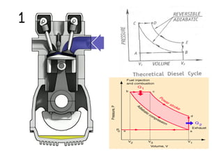
1. Suction stroke
At the beginning of the suction stroke, the piston is at the TDC, and is about to
move towards the BDC.
At this instance, the inlet valve is opened and the exhaust valve is closed.
The downward movement of the piston produces suction in the cylinder, due to
which fresh air is drawn into the cylinder through the inlet valve.
When the piston reaches the BDC, the suction stroke ends and the inlet valve is
closed. With this stroke, the crankshaft rotates through 180° or half-revolution.
The energy required for the piston movement is taken from a battery. The suction
of air takes place at atmospheric pressure, and is represented by the line e-a on
p-v diagram.
22.
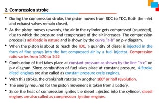
2. Compression stroke
During the compression stroke, the piston moves from BDC to TDC. Both the inlet
and exhaust valves remain closed.
As the piston moves upwards, the air in the cylinder gets compressed (squeezed),
due to which the pressure and temperature of the air increases. The compression
process is adiabatic in nature and is shown by the curve “a-b” on p-v diagram.
When the piston is about to reach the TDC, a quantity of diesel is injected in the
form of fine sprays into the hot compressed air by a fuel injector. Compression
ratio varies from 1:20 to 1:22
Combustion of fuel takes place at constant pressure as shown by the line “b-c” on
p-v diagram. Since combustion of fuel takes place at constant pressure, 4-Stroke
diesel engines are also called as constant pressure cycle engines.
With this stroke, the crankshaft rotates by another 180° or half revolution.
The energy required for the piston movement is taken from a battery.
Since the heat of compression ignites the diesel injected into the cylinder, diesel
engines are also called as compression ignition engines.
23.
3. Power stroke(Expansion stroke or Working stroke)
• During this stroke, both the valves will remain closed. As the combustion of fuel
takes place, the burnt gases expand and exert a large force on the piston causing it
to move rapidly from the TDC to BDC. The force (or power) is transmitted to the
crankshaft through the connecting rod.
• The expansion of gases is adiabatic in nature and is shown by the curve c-d on p-v
diagram.
• Since the actual power or work is produced by the engine in this stroke, it is also
called as power stroke or working stroke. Also, expansion of gases occurs during
this stroke, and hence the name expansion stroke.
• Towards the end of the expansion stroke, the exhaust valve opens, while the inlet
valve remains closed.
• This drop in pressure at constant volume inside the cylinder is represented by the
line d-a on p-v diagram. With this stroke, the crankshaft rotates through 180° or
half-revolution.
24.
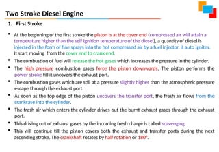
• The exhauststroke begins when the piston starts moving from the BDC to
TDC.
• The energy for this stroke is supplied by the flywheel, which it had absorbed
in the previous stroke.
• As the piston moves upwards, it forces the remaining burnt gases to the
atmosphere through the exhaust valve. The exhaust taking place at
atmospheric pressure is shown by the line a-e on p-v diagram. With this
stroke, the crankshaft rotates through 180° or half-revolution.
• When the piston reaches the TDC, the exhaust valve closes and the working
cycle is completed. In the next cycle, the piston starts moving from TDC to
BDC, the inlet valve opens allowing fresh air enter into the cylinder, and the
process continues.
• Thus it is clear that, the four different strokes or one working cycle is
completed when the crankshaft rotates through 720° or two revolutions.
• Four-stroke diesel engines are commonly used in Trucks, bus etc.
4. Exhaust stroke
25.
In two strokecycle engines, the suction and exhaust strokes are eliminated. There are only
two remaining strokes i.e., the compression stroke and power stroke and these are usually
called upward stroke and downward stroke. Also, instead of valves, there are inlet and
exhaust ports in two stroke cycle engines.
Two Stroke Petrol Engine
Two Stroke PetrolEngine
1. First Stroke
At the beginning of the first stroke the piston is at the cover end. The spark plug
ignites the compressed petrol-air mixture. It start moving from the cover end to crank
end.
The combustion of the petrol will release the hot gases which increases the pressure
in the cylinder.
The high pressure combustion gases force the piston downwards. The piston performs
the power stroke till it uncovers the exhaust port.
The combustion gases which are still at a pressure slightly higher than the
atmospheric pressure escape through the exhaust port.
As soon as the top edge of the piston uncovers the transfer port, the fresh petrol-air
mixture flows from the crankcase into the cylinder.
The fresh petrol-air mixture which enters the cylinder drives out the burnt exhaust
gases through the exhaust port.
This driving out of exhaust gases by the incoming fresh charge is called scavenging.
This will continue till the piston covers both the exhaust and transfer ports during the
next ascending stroke. The crankshaft rotates by half rotation or 180°.
29.
Two Stroke PetrolEngine
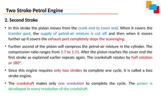
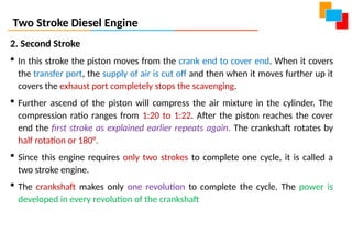
2. Second Stroke
• In this stroke the piston moves from the crank end to cover end. When it covers the
transfer port, the supply of petrol-air mixture is cut off and then when it moves
further up it covers the exhaust port completely stops the scavenging.
• Further ascend of the piston will compress the petrol-air mixture in the cylinder. The
compression ratio ranges from 1:7 to 1:11. After the piston reaches the cover end the
first stroke as explained earlier repeats again. The crankshaft rotates by half rotation
or 180°.
• Since this engine requires only two strokes to complete one cycle, it is called a two
stroke engine.
• The crankshaft makes only one revolution to complete the cycle. The power is
developed in every revolution of the crankshaft
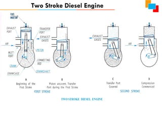
Two Stroke DieselEngine
1. First Stroke
At the beginning of the first stroke the piston is at the cover end (compressed air will attain a
temperature higher than the self ignition temperature of the diesel), a quantity of diesel is
injected in the form of fine sprays into the hot compressed air by a fuel injector, it auto ignites.
It start moving from the cover end to crank end.
The combustion of fuel will release the hot gases which increases the pressure in the cylinder.
The high pressure combustion gases force the piston downwards. The piston performs the
power stroke till it uncovers the exhaust port.
The combustion gases which are still at a pressure slightly higher than the atmospheric pressure
escape through the exhaust port.
As soon as the top edge of the piston uncovers the transfer port, the fresh air flows from the
crankcase into the cylinder.
The fresh air which enters the cylinder drives out the burnt exhaust gases through the exhaust
port.
This driving out of exhaust gases by the incoming fresh charge is called scavenging.
This will continue till the piston covers both the exhaust and transfer ports during the next
ascending stroke. The crankshaft rotates by half rotation or 180°.
32.
Two Stroke DieselEngine
2. Second Stroke
In this stroke the piston moves from the crank end to cover end. When it covers
the transfer port, the supply of air is cut off and then when it moves further up it
covers the exhaust port completely stops the scavenging.
Further ascend of the piston will compress the air mixture in the cylinder. The
compression ratio ranges from 1:20 to 1:22. After the piston reaches the cover
end the first stroke as explained earlier repeats again. The crankshaft rotates by
half rotation or 180°.
Since this engine requires only two strokes to complete one cycle, it is called a
two stroke engine.
The crankshaft makes only one revolution to complete the cycle. The power is
developed in every revolution of the crankshaft
33.
Sl.
No Petrol EngineDiesel Engine
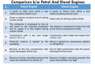
1.
It works on Otto Cycle which is also
called constant volume cycle
It works on Diesel Cycle which is also
called constant pressure cycle
2.
Draws a mixture of petrol and air during
suction stroke Draws only air during suction stroke
3.
The carburetor is employed to mix air
and petrol in the required proportion
and to supply it to the engine during
suction stroke
The injector is employed to inject the fuel
at the end of compression stroke.
4.
Compression ratio is less and ranges
from 1:7 to 1:11
Compression ratio is high and ranges from
1:20 to 1:22
5.
Petrol-Air mixture is ignited by the
sparkplug
Diesel is ignited by compression ignition
or self-ignition
6.
Because of the low compression ratio
power developed will be less
Due to high compression ratio the power
developed will be more
7. Because of lower operating pressure the
noise and vibrations are almost nil
Because of higher operating pressure the
noise and vibrations are high
Comparison b/w Petrol And Diesel Engines
34.
Sl.
No Petrol EngineDiesel Engine
8. Weight of the engine is less Weight of the engine is more
9. Initial cost of the engine is less Initial cost of the engine is more
10.
Running or Operating cost is high
because petrol is costlier
Running or Operating cost is less because
diesel is cheaper
11. Maintenance cost is Less Maintenance cost is slightly higher
12.
The petrol engines can easily be started
even in cold weather
The diesel engines are difficult to start in
cold weather
13. Thermal efficiency is less due to lower
compression ratio. It is around 26%
Thermal efficiency is high due to higher
compression ratio. It is around 40%
14. Used in Scooter, Bikes, Cars, etc,.
Used in Trucks, Tractors, Buses, Bulldozers,
etc,.
Comparison b/w Petrol And Diesel Engines
35.
Sl.
No 4-Stroke Engine2-Stroke Engine
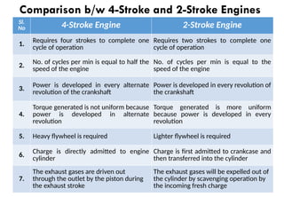
1.
Requires four strokes to complete one
cycle of operation
Requires two strokes to complete one
cycle of operation
2.
No. of cycles per min is equal to half the
speed of the engine
No. of cycles per min is equal to the
speed of the engine
3. Power is developed in every alternate
revolution of the crankshaft
Power is developed in every revolution of
the crankshaft
4.
Torque generated is not uniform because
power is developed in alternate
revolution
Torque generated is more uniform
because power is developed in every
revolution
5. Heavy flywheel is required Lighter flywheel is required
6.
Charge is directly admitted to engine
cylinder
Charge is first admitted to crankcase and
then transferred into the cylinder
7.
The exhaust gases are driven out
through the outlet by the piston during
the exhaust stroke
The exhaust gases will be expelled out of
the cylinder by scavenging operation by
the incoming fresh charge
Comparison b/w 4-Stroke and 2-Stroke Engines
36.
Sl.
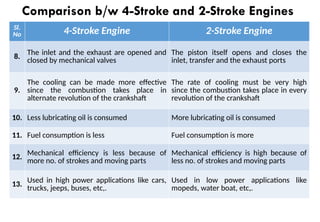
No 4-Stroke Engine2-Stroke Engine
8.
The inlet and the exhaust are opened and
closed by mechanical valves
The piston itself opens and closes the
inlet, transfer and the exhaust ports
9.
The cooling can be made more effective
since the combustion takes place in
alternate revolution of the crankshaft
The rate of cooling must be very high
since the combustion takes place in every
revolution of the crankshaft
10. Less lubricating oil is consumed More lubricating oil is consumed
11. Fuel consumption is less Fuel consumption is more
12. Mechanical efficiency is less because of
more no. of strokes and moving parts
Mechanical efficiency is high because of
less no. of strokes and moving parts
13. Used in high power applications like cars,
trucks, jeeps, buses, etc,.
Used in low power applications like
mopeds, water boat, etc,.
Comparison b/w 4-Stroke and 2-Stroke Engines
37.
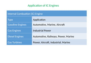
Internal Combustion (IC)Engine
Type Application
Gasoline Engines Automotive, Marine, Aircraft
Gas Engines Industrial Power
Diesel Engines Automotive, Railways, Power, Marine
Gas Turbines Power, Aircraft, Industrial, Marine
Application of IC Engines
38.
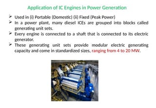
Application of ICEngines in Power Generation
Used in (i) Portable (Domestic) (ii) Fixed (Peak Power)
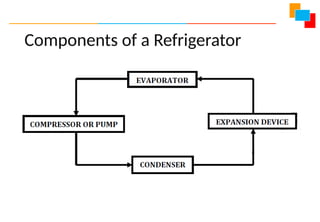
In a power plant, many diesel ICEs are grouped into blocks called
generating unit sets.
Every engine is connected to a shaft that is connected to its electric
generator.
These generating unit sets provide modular electric generating
capacity and come in standardized sizes, ranging from 4 to 20 MW.
39.
Application of ICEngines in Agriculture
Uses of IC engine allow faster production, more food to be grown and
harvested.
The different tasks to be performed ploughing, sowing, weeding,
harvesting etc.
Tractors, planters and combiners all with powered with IC engines to
plant and harvest crops.
40.
Application of ICEngines in Marine
Marine engine on ships are responsible for the propulsion of the
vessel from one port to another.
The engines used on board ships ((i) Outboard (ii) Inboard) are internal
combustion engines, in which, the combustion of fuel takes place
inside the engine cylinder and the heat is generated post combustion
process.
The ships of all types from goods to cruise and small boats are run by
IC engines.
41.
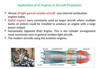
Application of ICEngines in Aircraft Propulsion
Almost all light general aviation aircraft uses internal combustion
engines today.
Radial engines were commonly used on larger aircraft where multiple
banks of pistons could be installed to produce an engine with a large
power output.
Horizontally Opposed (Flat) Engine. This is the cylinder arrangement
most commonly seen in general aviation light aircraft.
The modern aircrafts using the turbofan engines.
42.
Application of ICEngines in Automobile
IC Engines are used in almost all the automobiles or road vehicles like
o Scooters,
o Motorcycles
o Cars,
o Buses
o Trucks and heavy vehicles etc.
o Earthmoving: (i) Dumpers (ii) Tippers (iii) Mining Equipment
The IC engines used may be petrol (SI) engines or Diesel engine.
43.
Electric and HybridVehicles, Components of Electric and Hybrid Vehicles, Drives and
Transmission. Advantages and disadvantages of EVs and Hybrid vehicles.
Insight Into Future Mobility Technology
Electric and Hybrid Vehicles
• An Electric vehicles is powered by an Electric Motor rather than a Gasoline
Engine.
• The Electric Motor gets its power from a controller.
• The Controller is powered from an array of rechargeable batteries.
The vehicle uses a large traction battery pack to power the electric motor
and must be plugged in to a wall outlet or charging equipment also called
electric vehicle supply equipment (EVSE).
Because it runs on electricity, the vehicle emits no exhaust from a tailpipe
and does not contain the typical liquid fuel components, such as a fuel
pump, fuel line, or fuel tank.
44.
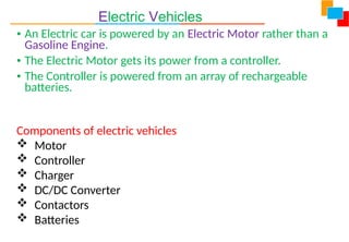
Electric Vehicles
• AnElectric car is powered by an Electric Motor rather than a
Gasoline Engine.
• The Electric Motor gets its power from a controller.
• The Controller is powered from an array of rechargeable
batteries.
Components of electric vehicles
Motor
Controller
Charger
DC/DC Converter
Contactors
Batteries
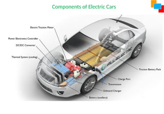
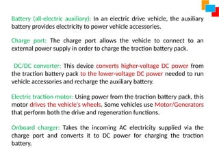
Battery (all-electric auxiliary):In an electric drive vehicle, the auxiliary
battery provides electricity to power vehicle accessories.
Charge port: The charge port allows the vehicle to connect to an
external power supply in order to charge the traction battery pack.
DC/DC converter: This device converts higher-voltage DC power from
the traction battery pack to the lower-voltage DC power needed to run
vehicle accessories and recharge the auxiliary battery.
Electric traction motor: Using power from the traction battery pack, this
motor drives the vehicle's wheels. Some vehicles use Motor/Generators
that perform both the drive and regeneration functions.
Onboard charger: Takes the incoming AC electricity supplied via the
charge port and converts it to DC power for charging the traction
battery.
47.
Power electronics controller:This unit manages the flow of electrical
energy delivered by the traction battery, controlling the speed of the
electric traction motor and the torque it produces.
Thermal system (cooling): This system maintains a proper operating
temperature range of the engine, electric motor, power electronics,
and other components. Traction battery pack: Stores electricity for use
by the electric traction motor.
Transmission (electric): The transmission transfers mechanical power
from the electric traction motor to drive the wheels.
48.
Advantages of EVs
•Less Strain on the Environment
• Electricity Is Renewable, Unlike Gasoline
• Low Maintenance
• Quieter and Smoother Motion
• Green Tax Credits Cut Costs
• Special Accommodations for EVs
Disadvantages of EVs
• High Upfront Costs
• Limited Selection
• Charging Complications
49.
Hybrid Engine
A hybridvehicle combines any two or more power (energy)
sources that can directly or indirectly provide propulsion
power is a hybrid.
Possible combinations include diesel/electric, gasoline/fly
wheel, and fuel cell (FC)/battery. Typically, one energy source
is storage, and the other is conversion of a fuel to energy.
The combination of two power sources may support two
separate propulsion systems. Thus to be a True hybrid, the
vehicle must have at least two modes of propulsion.
50.
These two powersources may be paired in series, meaning
that the gas engine charges the batteries of an electric
motor that powers the car or in parallel, with both
mechanisms driving the car directly.
Today's hybrid electric vehicles (HEVs) are powered by an
internal combustion engine in combination with one or more
electric motors that use energy stored in batteries.
51.
Components of HybridVehicles
• The hybrid electric vehicle combines a gasoline engine
with an electric motor.
• An alternate arrangement is a diesel engine and an
electric motor.
52.
Cont…
HEV is formedby merging components from a pure electrical vehicle
and a pure gasoline vehicle.
The Electric Vehicle (EV) has an M/G (Motor/Generator) which allows
regenerative braking for an EV;
The M/G installed in the HEV enables regenerative braking.
For the HEV, the M/G is inserted directly behind the engine.
The transmission appears next in line.
This arrangement has two torque producers; the M/G in motor mode,
M-mode, and the gasoline engine.
The battery and M/G are connected electrically.
53.
Drives and Transmission
•The power generated in the electric vehicle motor is transferred to a
drive wheel via gearbox.
• The EV uses single-speed transmission because the motor is efficient in
wide range of condition.
• The output speed of motor is reduced in two steps that is speed
reduction and torque multiplication.
• A significant difference between conventional vehicles and EVs is the
drivetrain.
• Simply put, the majority of EVs do not have multi-speed transmissions.
Instead, a single-speed transmission regulates the electric motor.
• A vehicle transmission transmits the rotating power of the energy
source, whether an electric motor or an internal combustion engine
(ICE), through a set of gears to a differential, the unit that spins the
wheels.
54.
Dr TSN, JSSATEB
Advantagesof Hybrid vehicles.
• Environmentally Friendly
• Financial Benefits
• Less Dependence on Fossil Fuels
• Regenerative Braking System
• Built From Light Materials
• Assistance From Electric Motor
• Smaller Engines
• Automatic Start and Stop
• Electric-Only Drive
55.
Dr TSN, JSSATEB
Disadvantagesof Hybrid vehicles.
• Less Power
• Expensive
• Poorer Handling
• Higher Maintenance Costs
• Accident from High Voltage in Batteries
• Battery Replacement is Pricey
• Battery Disposal and Recycling
56.
Principle of refrigeration,Refrigeration effect, Ton of Refrigeration, COP, Refrigerants
and their desirable properties. Principles and Operation of Vapor Compression and
Vapor absorption refrigeration. Domestic and Industrial Applications of Refrigerator.
Refrigeration and Air-Conditioning
Refrigeration
“Refrigeration is defined as a method of reducing the temperature of a
system below that of the surroundings and maintaining it at the lower
temperature by continuously abstracting the heat from it.”
57.
Applications of Refrigeration
Foodprocessing, preservation and distribution
Chemical and process industries
Special Applications such as cold treatment of metals, medical,
construction etc.,
Comfort & Commercial air-conditioning
Industrial, such as in textiles, printing, manufacturing, photographic,
computer rooms, power plants, vehicular etc..
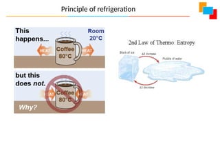
• Heat naturaltransfers from a region of higher temperature to lower
temperature.
• Vice versa is only possible by aid of external work as per 2nd
law of
thermodynamics.
• “It is impossible for a self acting machine, working in a cyclic
process, to transfer heat from a body at a lower temperature to
body at a higher temperature without the aid of an external
agency”.
Principle of Refrigeration
60.
Concepts related torefrigeration
1. Refrigeration effect:
In a refrigeration system, the rate at which the heat is absorbed in a cycle from the
interior refrigerating space to be cooled is called Refrigeration effect. Specified by
kJ/sec or kW
2. A Ton of refrigeration:
It is defined as the quantity of heat absorbed in order to form one ton of ice in 24 hours
when the initial temperature of the water is 0°C.
1 Ton of refrigeration = 210 kJ/min = 3.5 kW
3. Ice making capacity:
It is the capacity of a refrigerating system to make solid ice beginning from water at
room temperature in one hour. Specified by kg/hr
61.
4. Coefficient ofPerformance (COP):
COP of a refrigerator is the ratio of heat absorbed from refrigerating
space to the work supplied.
5. Relative COP:
R-COP is the ratio of Actual COP to the Theoretical COP
62.
6. Refrigerant:
A Refrigerantis medium it continuously extracts the heat from the
space within the refrigerator which is to be kept cool at temperatures
less than the atmosphere and finally rejects to it to the surroundings.
Most Commonly used refrigerants:
7. Ammonia – Vapour Absorption Refrigerator
8. Carbon dioxide – Marine Refrigerators
9. Sulphur dioxide – House Hold Refrigerators
10. Methyl chloride – Small Scale Industrial Refrigeration and
House Hold Refrigerators
11. Freon 12 – Domestic Vapour Compression Refrigerators
12. Freon 22 – Air Conditioners
63.
• Ammonia
• Highlatent heat, low specific volume, high refrigeration effects even for small
units, no harm to the ozone, toxic, flammable, unsuitable for domestic
refrigerators.
• Carbon dioxide
• Low COP so not used in domestic refrigerators, used in dry ice making, colorless,
odorless, non toxic, non flammable and non corrosive, unsuitable for domestic
refrigerators.
• Sulphur dioxide
• Low refrigerating effect, high specific volume (require large capacity high speed
compressors), toxic and corrosive with water, Seldom used (not often used).
• Methyl chloride
• Toxic and flammable and hence Seldom used(not often used).
• Freon
• Most universally used in domestic refrigerators, colorless, almost odorless, non
toxic, non flammable, non explosive, non corrosive, high COP, Threat to ozone.
65.
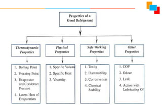
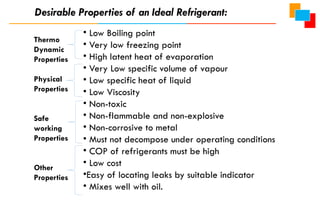
• Low Boilingpoint
• Very low freezing point
• High latent heat of evaporation
• Very Low specific volume of vapour
• Low specific heat of liquid
• Low Viscosity
• Non-toxic
• Non-flammable and non-explosive
• Non-corrosive to metal
• Must not decompose under operating conditions
• COP of refrigerants must be high
• Low cost
•Easy of locating leaks by suitable indicator
• Mixes well with oil.
Desirable Properties of an Ideal Refrigerant:
Thermo
Dynamic
Properties
Physical
Properties
Safe
working
Properties
Other
Properties
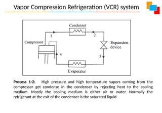
Vapor Compression Refrigeration(VCR) system
Process 1-2: High pressure and high temperature vapors coming from the
compressor get condense in the condenser by rejecting heat to the cooling
medium. Mostly the cooling medium is either air or water. Normally the
refrigerant at the exit of the condenser is the saturated liquid.
70.
Vapor Compression Refrigeration(VCR) system
Process 2-3: The liquid coming from the condenser passes through the
expansion device (throttling valve) where pressure of saturated liquid decreases
from the condenser pressure to the evaporator pressure. The expansion device
reduces the pressure and temperature of the refrigeration.
Process 3-4: Low pressure liquid coming out of the expansion device enters the
evaporator. Here refrigerant evaporates, thus absorbing heat from the
surrounding. The absorption of heat by liquid converts it into the superheated
vapors at low pressure and temperature.
Process 4-1: Low pressure and low temperature vapors from the evaporator are
sucked by the compressor. The compressor compresses the vapors to the high
pressure and its temperature also increases. Thus, the condition of vapors at the
exit of the compressor is at high temperature and pressure and the cycle is
completed.
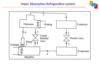
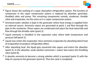
Figure showsthe working of a vapor absorption refrigeration system. The function of
compressor in the vapor compression system is replaced by absorber, generator,
throttled valve and pump. The remaining components namely, condenser, throttle
valve and evaporator, are the same as in a vapor compression system.
Ammonia-water solution is kept in the generator where heat energy is supplied from
an external source. Ammonia vapors are generated at point 1 and flow through the
pipe to the condenser. These vapors are condensed and reject the heat externally and
flow through the throttle valve (point 2).
Liquid ammonia is throttled in the expansion valve where both temperature and
pressure fall (point 3).
Liquid now enters the evaporator. Here ammonia evaporates by absorbing latent heat
of evaporation to produce refrigeration effect.
After absorbing heat, the liquid gets converted into vapors and enters the absorber
(point 4). In the absorber, weak solution (ammonia + water) also enters the throttling
valve (point 8).
It absorbs ammonia to become a strong solution which is pumped (point 5) with the
help of a pump to the generator (point 6). Thus the cycle is completed.
Cont’d…………
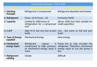
Comparison between VCR& VAR
Details Vapour Compression Vapour Absorption
1. Working
Principle
Refrigerant is compressed Refrigerant absorbed and heated
2. Refrigerant Freon -12 & Freon – 22 Ammonia (NH3)
3. Capacity Limited to 1000 tones of
refrigeration for a compressor
unit
Above 1000 tons (Not suitable for
small capacities)
4. C.O.P High (4-5), but very low at part
loads
Low , but same as full and part
loads
5. Type of Energy
supplied
Mechanical Energy Heat energy
6. Mechanical
energy input
Refrigerant vapour is
compressed to high pressure,
so mechanical energy input is
more
Pump has to only circulate the
refrigerant. Therefore, mechanical
energy input to run the pump is
less
7. Refrigerant
refilling
Simple Difficult
77.
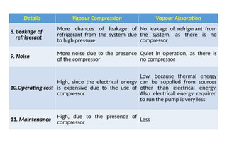
Details Vapour CompressionVapour Absorption
8. Leakage of
refrigerant
More chances of leakage of
refrigerant from the system due
to high pressure
No leakage of refrigerant from
the system, as there is no
compressor
9. Noise
More noise due to the presence
of the compressor
Quiet in operation, as there is
no compressor
10.Operating cost
High, since the electrical energy
is expensive due to the use of
compressor
Low, because thermal energy
can be supplied from sources
other than electrical energy.
Also electrical energy required
to run the pump is very less
11. Maintenance High, due to the presence of
compressor Less
78.
Working principles ofAir Conditioning
Air conditioning is conditioning of air for human comfort or for industrial purposes by
artificial cooling, controlling humidity and cleaning of air.
The device continuously draws air from an indoors space which is required to cool,
it cools in refrigeration system and discharge back into the same indoor space.
This continuous cyclic process of drawing, cooling, and recirculation of the cooled
air maintains indoor space cool at the required lower temperature which is required
for comfort cooling or industrial cooling.
79.
Classification
1. According toarrangement of equipment's
a. Unitary system: In this system different component of air conditioning system
is manufactured and assembled as unit in a factory. This unit is installed in or
near to space to be conditioned.
1. Window air conditioner
2. Split air conditioner
3. Packaged air conditioner
b. Central system: In this system different components are manufactured in
factory and assembled at the site. This type of system is used for conditioning of
air in theatres, cinemas, restaurants, exhibition halls, big factory space etc.
Air Conditioning
80.
2. According tothe purpose
1. Comfort air conditioning system
2. Industrial air conditioning system
3. According to season of year
1. Winter air conditioning system:
Air is heated and humidified
2. Summer air conditioning system:
Air is cooled and dehumidified
Air Conditioning
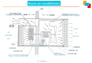
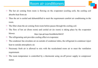
o Thehot air coming from room is flowing on the evaporator (cooling coil), the cooling coil
absorbs heat from air.
o Thus the air is cooled and dehumidified to meet the requirement comfort air conditioning in the
room.
o The filter clean the air coming from room before passes through the cooling coil.
o The flow of hot air (from room) and cooled air (to room) is taking place by the evaporator
blower.
o The refrigerating unit provides cooling effect at evaporator.
o The condenser fan circulates air on outside of condenser tubes, the refrigerant in condenser reject
heat to outside atmospheric air.
o Necessary fresh air is allowed to mix with the recalculated room air to meet the ventilation
requirement.
o The room temperature is controlled by a thermostat using on-off power supply to compressor
motor.
https://goo.gl/maps/JSuioDBoNuFdtk537
Room air conditioners
The applications ofair-conditioning are quite diverse. Applications and few
important areas are listed below.
Air-conditioning of theatres, cinema houses, Television studio
Hospitals, hotels, restaurants
Aircraft
Automobiles – buses, cars, Railway etc.
Offices, homes
Textile industry
Air-conditioning in photographic industry
Marine air-conditioning
Applications of Air-conditioning
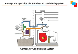
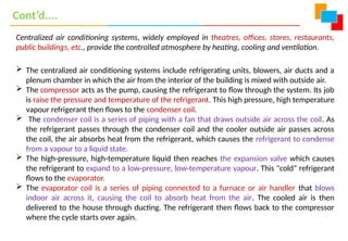
Centralized air conditioningsystems, widely employed in theatres, offices, stores, restaurants,
public buildings, etc., provide the controlled atmosphere by heating, cooling and ventilation.
The centralized air conditioning systems include refrigerating units, blowers, air ducts and a
plenum chamber in which the air from the interior of the building is mixed with outside air.
The compressor acts as the pump, causing the refrigerant to flow through the system. Its job
is raise the pressure and temperature of the refrigerant. This high pressure, high temperature
vapour refrigerant then flows to the condenser coil.
The condenser coil is a series of piping with a fan that draws outside air across the coil. As
the refrigerant passes through the condenser coil and the cooler outside air passes across
the coil, the air absorbs heat from the refrigerant, which causes the refrigerant to condense
from a vapour to a liquid state.
The high-pressure, high-temperature liquid then reaches the expansion valve which causes
the refrigerant to expand to a low-pressure, low-temperature vapour. This "cold“ refrigerant
flows to the evaporator.
The evaporator coil is a series of piping connected to a furnace or air handler that blows
indoor air across it, causing the coil to absorb heat from the air. The cooled air is then
delivered to the house through ducting. The refrigerant then flows back to the compressor
where the cycle starts over again.
Cont’d....
87.
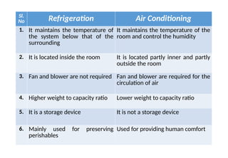
Sl.
No Refrigeration AirConditioning
1. It maintains the temperature of
the system below that of the
surrounding
It maintains the temperature of the
room and control the humidity
2. It is located inside the room It is located partly inner and partly
outside the room
3. Fan and blower are not required Fan and blower are required for the
circulation of air
4. Higher weight to capacity ratio Lower weight to capacity ratio
5. It is a storage device It is not a storage device
6. Mainly used for preserving
perishables
Used for providing human comfort