This document provides information on internal combustion engines, including:
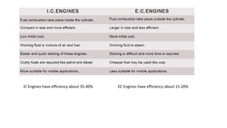
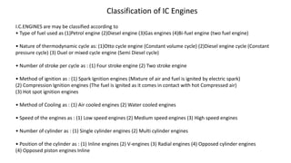
1. It defines internal combustion engines and classifies them based on where combustion occurs, fuel used, thermodynamic cycle, number of strokes, ignition method, cooling method, and more.
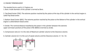
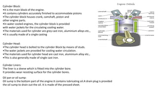
2. It describes the basic components of an IC engine like the cylinder block, cylinder head, piston, connecting rod, crankshaft, and camshaft.
3. It explains the four strokes of a typical four-stroke engine cycle and compares it to the two-stroke engine cycle.


![PROBLEM 1
Data recorded during testing of a TWO STROKE
gas engine is
Diameter of the piston d= 150 mm
Stroke length L= 180 mm ,
Clearance volume Vc = 0.89 liter
RPM of the engine N = 300 ,
Indicated mean effective pressure pm= 6.1 bars
Gas consumption m. = 6.1 m3/h,
Calorific value of the gas (fuel) CF = 17000 kJ/m3
Determine the followings:
•Air Standard Efficiency
•Indicated power (IHP)developed by the engine
•Indicated thermal efficiency of the engine
SOLUTION
Swept volume Vs = πd2L/4
= π(0.150)2 x 180/4 = 0.00318 m3
Clearance volume Vc= 0.00089 m3
Total volume = Swept volume + clearance volume
VT = 0.00318 + 0.00089 = 0.00407 m3
Compression ratio γ = Total volume/Clearance volume
= 0.00407/0.00089 = 4.573
•Air standard Efficiency η = 1 –1/(r)γ—1
•= 1—1/(4.573)4—1
= 0.456 = 45.6 %
•Indicated power IHP = 100 p L AN/60 when p is in bars
= 100 x 6.1x 0.180 x [π(0.150)2/4] 300/60 = 9700 W
(c ) Indicated Thermal Efficiency
ηIT = Indicated power in (kJ/s)/Heat supplied in (kJ/s)
= (9700/1000)/(6.1 x 17000/3600) = 0.3367 = 33.67 %](https://image.slidesharecdn.com/module5teintroduction-230821140220-8c92b5fc/85/Module-5-_TE_-Introduction-pptx-36-320.jpg)


