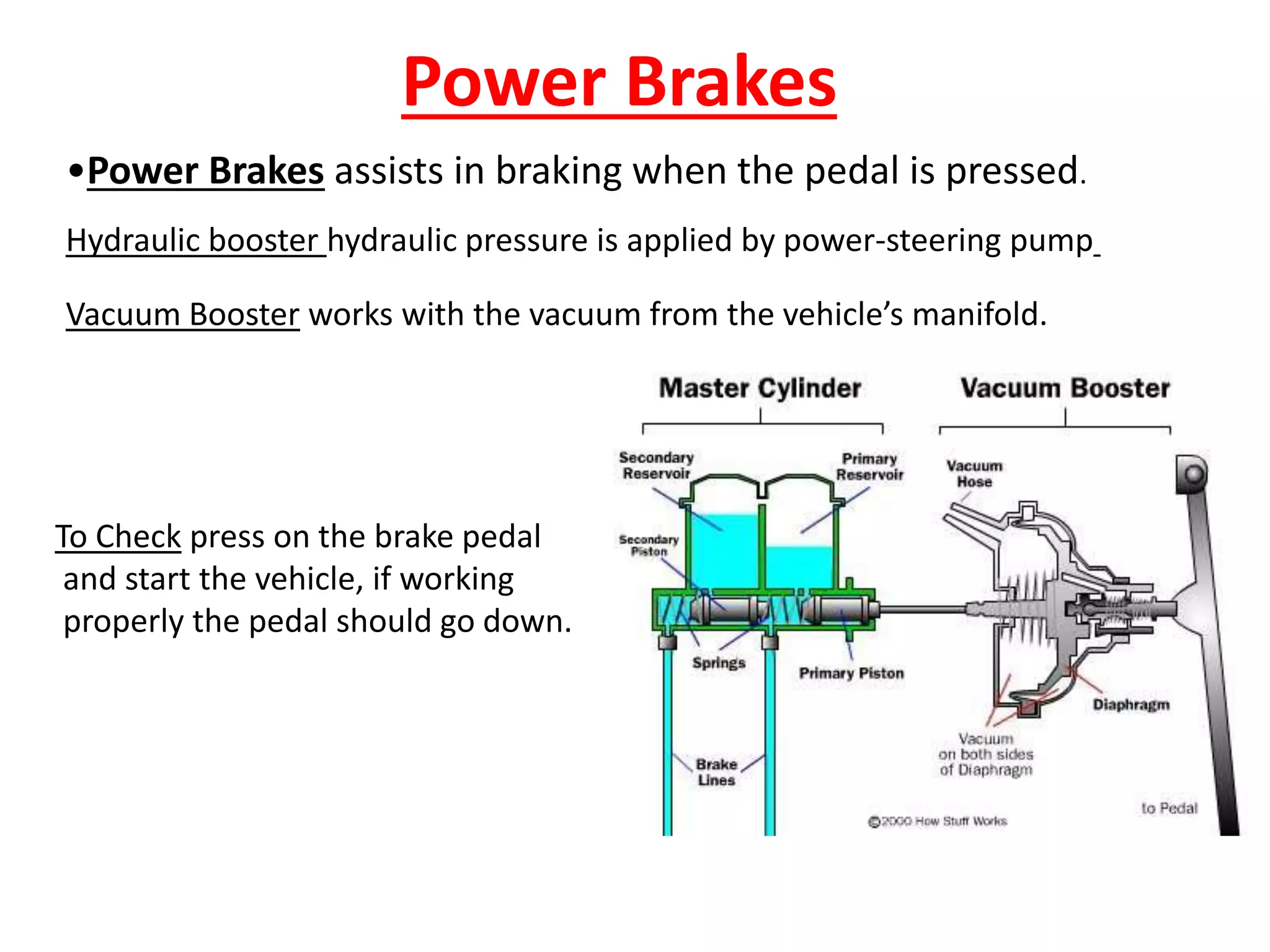
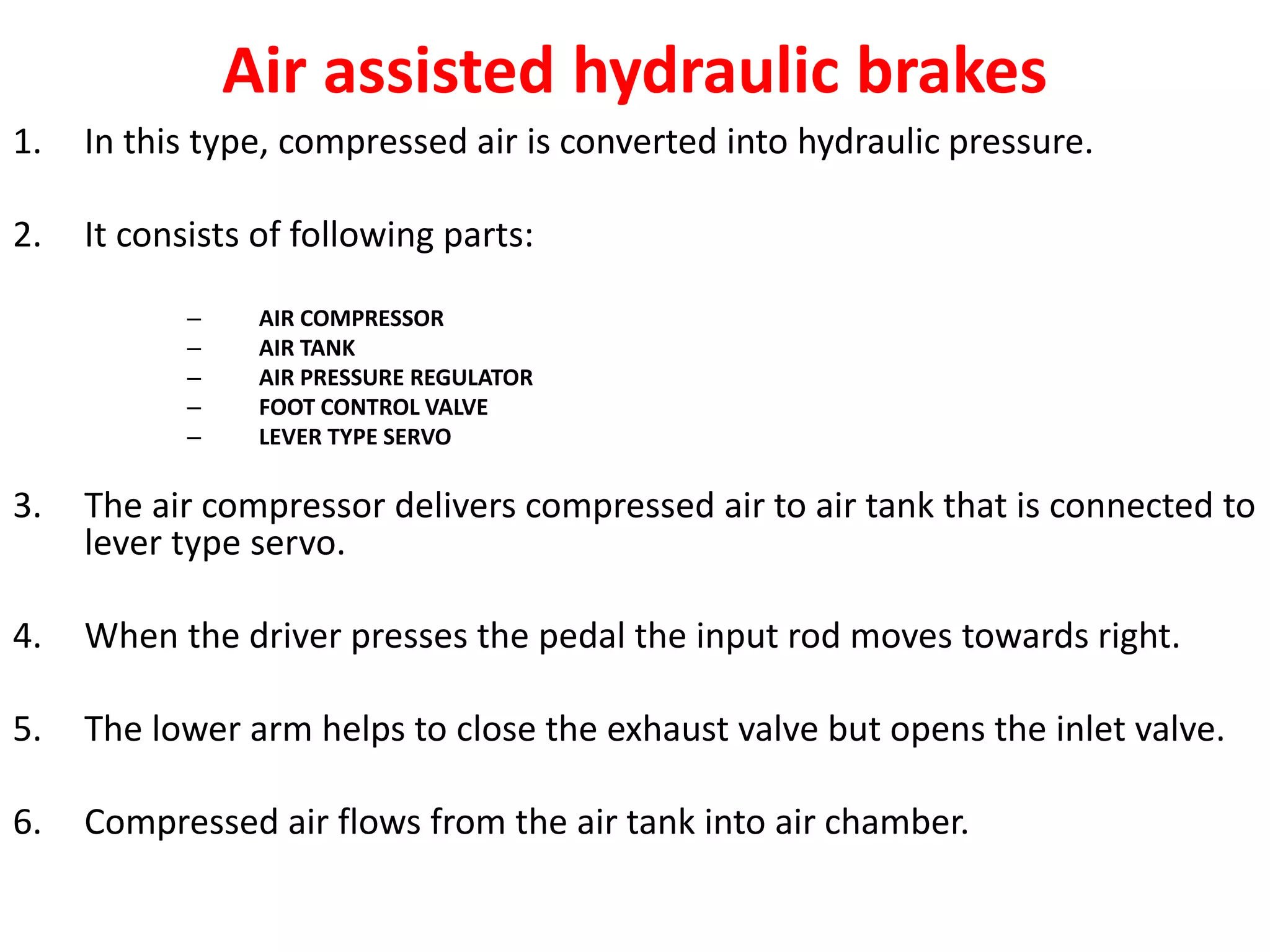
SlideShare a Scribd company logo
Power Assisted Brakes
Power Brakes
•Power Brakes assists in braking when the pedal is pressed.
Hydraulic booster hydraulic pressure is applied by power-steering pump
Vacuum Booster works with the vacuum from the vehicle’s manifold.
To Check press on the brake pedal
and start the vehicle, if working
properly the pedal should go down.
CONTENTS
• POWER ASSISTED BRAKES
–Air assisted hydraulic brakes
–Vaccum assisted hydraulic brakes
• SERVO BRAKES
– Mechanical servo mechanism
– Hydraulic servo brakes
– Vaccum servo brakes
Air assisted hydraulic brakes
1. In this type, compressed air is converted into hydraulic pressure.
2. It consists of following parts:
– AIR COMPRESSOR
– AIR TANK
– AIR PRESSURE REGULATOR
– FOOT CONTROL VALVE
– LEVER TYPE SERVO
3. The air compressor delivers compressed air to air tank that is connected to
lever type servo.
4. When the driver presses the pedal the input rod moves towards right.
5. The lower arm helps to close the exhaust valve but opens the inlet valve.
6. Compressed air flows from the air tank into air chamber.
7. The pressure, forces the piston to move right, so
the effort being transferred to master cylinder.
8. The force on the master cylinder piston creates
hydraulic pressure for the application of brakes.
9. On release of pedal, pressure movement of lower
arm opens the exhaust valve and inlet valve
remains closed.
10.The entire air pressure in the chamber is released
into the atmosphere.
Vaccum assisted hydraulic brakes
1. In this type, Vaccum system assists in the operation of hydraulic
brake.
2. The main parts of the system are:
– VACCUM BOOSTER
– VACCUM TANK
3. Here the Vaccum booster helps operating the master cylinder.
4. Vaccum booster has a cylinder. Inside the cylinder a piston
operates a control valve to admit and stop the engine Vaccum
and atmospheric pressure.
5. The atmospheric valve remains closed when the brakes are not
applied.
Working
1. When the brake pedal is depressed the atmospheric valve
and Vaccum valve also opens.
2. Now the piston moves by Vaccum created in the Vaccum
cylinder.
3. The piston is connected to the control arm.
4. The open end of the control arm is connected to pushrod of
the master cylinder.
5. Which it turns pushes the piston of the master cylinder.
6. The brake oil pushed to all wheel cylinders under pressure
and the brakes are applied.
Servo brakes
Note:- Servo brakes or Power Brakes
Servo mechanism
• Any mechanism which adds to the drivers
effort in applying the brakes is called a servo
mechanism.
• Although that effort remains a considerable
part of the total braking effort required.
Why servo is used in automobile
• As the weight of vehicle goes on increasing, more
braking effort is needed to stop the vehicle.
• When a limit is reached above, which is not possible
for an ordinary driver to apply the effort needed
conveniently.
• This limit is normally reached at about 3 times the
weight of the vehicle.
• To solve this problem by the help of the servo action.
Types of servo brakes
– Mechanical servo mechanism
– Hydraulic servo brakes
– Vaccum servo brakes
HYDRAULIC SERVO BRAKES
• when extra oil under pressure supplied by a pump
driven by the engine or some part of the
transmission system is used to assist the braking
effort, this system is called hydraulic servo brakes.
HYDRAULIC SERVO BRAKES
Construction
1. It consists of pump which forces the fluid from the tank.
2. Through the servo unit, oil back to the tank until the brake pedal is
pressed.
3. The inlet pipe is connected at A and the outlet at B to the servo unit.
4. The servo unit consists of a master cylinder with piston which is provided
with pipes for brakes.
5. A reservoir is connected to master cylinder for providing brake fluid.
6. A plunger is provided in the right side portion of the unit, which is pivoted
with the brake pedal rod.
7. A space S is provided between the master cylinder, piston and plunger for
building up the fluid pressure.
Working
• when the brake pedal is at off position then the plunger rests at its right
extreme position there by flowing the fluid through space S from inlet A to
the outlet B of the unit.
• when the brake pedal is pressed it results cut-off, the fluid at outlet B.
• Therefore, the pressure build up in the space S pushes the master cylinder.
• The piston moves towards left there by applying the brakes.
• When the pedal is released the pressure of fluid in space S is exerted on
the left side of the plunger, there by pushing the plunger toward right and
opening the passage at B.
• When the vehicle is at rest ,the servo system is not operative and the
compete unit functions just as ordinary hydraulic braking system.
VACCUM SERVO BRAKES
History
• Albert Dewandre (Liege, Belgium), an engineer and business
owner, was the inventor of servo-brake or brake booster
system in 1927.
• It is a brake boosting system that uses the depression caused
by the suction in the intake manifold of an internal
combustion engine to reduce the pressure on the brake
pedal.
• The advantage of the Dewandre system is two fold:
1. A softer push on the brake pedal,
2. But also a notably shorter braking distance.
• His invention was manufactured and sold through the Robert
Bosch Company.
VACCUM SERVO BRAKES
• When the Vaccum is obtained from the
manifold of the engine or a separate driven
exhauster used to assist the braking effort.
• This system is called Vaccum servo brakes.
construction
1. The system consists of a Vaccum reservoir connected through a non-return valve
to the inlet manifold of the engine.
2. Two connections from Vaccum reservoir, one on each side of the piston of the
servo cylinder is provided.
3. On left side the connections are through the control unit where as the right side
is connected directly.
4. The piston of the servo cylinder is further connected to the piston of the booster
cylinder.
5. The control unit consists of a piston to which two valves are attached.
6. The lower valve controls the connection between the reservoir and the right side
of the servo cylinder piston.
7. The upper valve controls the connection between the atmosphere and the left
side of servo cylinder piston.
8. The other side of the piston of the control unit is actuated by the pedal effort
through a master cylinder.
working
1. When the brake pedal is at off position, then the lower valve is opened and the
upper valve is closed.
2. Under this position the air from the atmosphere is disconnected and the Vaccum
from reservoir is created on the both sides of the piston of the servo cylinder.
3. When the brake pedal is pressed the brake fluid pushes the piston in the control
unit.
4. This Acton closes the lower valve and opens the upper valve of the control unit.
5. Thereby exposing the left side of the servo cylinder piston to atmospheric
pressure and acting the Vaccum on the right side.
6. This action of the Vaccum in the right side of the servo piston moves it to the
right.
7. There by utilizing this movement through the mechanical or hydraulic means it
the wheel cylinders and applying the brakes.

More Related Content

What's hot

Brakes
BrakesBrakes
Clutches ( Single Plate and Multi Plate)
Clutches ( Single Plate and Multi Plate) Clutches ( Single Plate and Multi Plate)
Clutches ( Single Plate and Multi Plate)
Shruti Mandaokar
 
4 independed suspension system
4 independed suspension system4 independed suspension system
4 independed suspension system
shaikusmanshag
 
Suspension system
Suspension systemSuspension system
Suspension system
Yashodhan Agarwal
 
2b9fc module iii steering system_ part-ii (2)
2b9fc module iii steering system_ part-ii (2)2b9fc module iii steering system_ part-ii (2)
2b9fc module iii steering system_ part-ii (2)
Tanvi Gautam
 
Clutches for automobile
Clutches for automobile Clutches for automobile
Clutches for automobile sgrsoni45
 
Vehicle Body Engineering - Introduction
Vehicle Body Engineering - IntroductionVehicle Body Engineering - Introduction
Vehicle Body Engineering - Introduction
Rajat Seth
 
A Seminar on drum brake
A Seminar on drum brakeA Seminar on drum brake
A Seminar on drum brake
Sk Samsuddin
 
Gearbox in automobile
Gearbox  in automobile Gearbox  in automobile
Gearbox in automobile sgrsoni45
 
rear axles.pptx
rear axles.pptxrear axles.pptx
rear axles.pptx
udaykumar435002
 
Braking system ppt
Braking system pptBraking system ppt
Braking system ppt
Rohityadav552
 
Automatic transmission system ppt
Automatic transmission system pptAutomatic transmission system ppt
Automatic transmission system ppt
PEC University Chandigarh
 
Frame and body of Automobile
Frame and body of AutomobileFrame and body of Automobile
Frame and body of Automobile
Ratnadeepsinh Jadeja
 
Fuel supply system in SI engines
Fuel supply system in SI enginesFuel supply system in SI engines
Fuel supply system in SI engines
Dr.Ramachandran Thulasiram
 
Synchromesh gear box
Synchromesh gear boxSynchromesh gear box
Synchromesh gear box
Parth Dasadiya Gnvantbhai
 
Multipoint Fuel Injection System (MPFI)
Multipoint Fuel Injection System (MPFI)Multipoint Fuel Injection System (MPFI)
Multipoint Fuel Injection System (MPFI)
Rutwij Patil
 
ppt of fuel injection system
ppt of fuel injection systemppt of fuel injection system
ppt of fuel injection system
Ayush Upadhyay
 
Wheel And tyres
Wheel And tyresWheel And tyres
Wheel And tyres
Khushin Lakshkar
 

What's hot (20)

Brakes
BrakesBrakes
Brakes
 
Clutches ( Single Plate and Multi Plate)
Clutches ( Single Plate and Multi Plate) Clutches ( Single Plate and Multi Plate)
Clutches ( Single Plate and Multi Plate)
 
4 independed suspension system
4 independed suspension system4 independed suspension system
4 independed suspension system
 
Suspension system
Suspension systemSuspension system
Suspension system
 
2b9fc module iii steering system_ part-ii (2)
2b9fc module iii steering system_ part-ii (2)2b9fc module iii steering system_ part-ii (2)
2b9fc module iii steering system_ part-ii (2)
 
Clutches for automobile
Clutches for automobile Clutches for automobile
Clutches for automobile
 
Carburettor
CarburettorCarburettor
Carburettor
 
Vehicle Body Engineering - Introduction
Vehicle Body Engineering - IntroductionVehicle Body Engineering - Introduction
Vehicle Body Engineering - Introduction
 
A Seminar on drum brake
A Seminar on drum brakeA Seminar on drum brake
A Seminar on drum brake
 
Gearbox in automobile
Gearbox  in automobile Gearbox  in automobile
Gearbox in automobile
 
rear axles.pptx
rear axles.pptxrear axles.pptx
rear axles.pptx
 
Braking system ppt
Braking system pptBraking system ppt
Braking system ppt
 
Automatic transmission system ppt
Automatic transmission system pptAutomatic transmission system ppt
Automatic transmission system ppt
 
Frame and body of Automobile
Frame and body of AutomobileFrame and body of Automobile
Frame and body of Automobile
 
Fuel supply system in SI engines
Fuel supply system in SI enginesFuel supply system in SI engines
Fuel supply system in SI engines
 
Braking systems
Braking systemsBraking systems
Braking systems
 
Synchromesh gear box
Synchromesh gear boxSynchromesh gear box
Synchromesh gear box
 
Multipoint Fuel Injection System (MPFI)
Multipoint Fuel Injection System (MPFI)Multipoint Fuel Injection System (MPFI)
Multipoint Fuel Injection System (MPFI)
 
ppt of fuel injection system
ppt of fuel injection systemppt of fuel injection system
ppt of fuel injection system
 
Wheel And tyres
Wheel And tyresWheel And tyres
Wheel And tyres
 

Similar to 7 power brakes

Project
ProjectProject
Project
Ajeet Kumar
 
Converter c8000
Converter c8000Converter c8000
Converter c8000
Gustavo De Haro
 
Valves
ValvesValves
Hydraulic ciruits
Hydraulic ciruitsHydraulic ciruits
Hydraulic ciruits
Abhishek Patange
 
08 ALS MK-III BS II STEERING SYSTEM.pptx
08 ALS MK-III BS II STEERING SYSTEM.pptx08 ALS MK-III BS II STEERING SYSTEM.pptx
08 ALS MK-III BS II STEERING SYSTEM.pptx
SauravkumarMallick1
 
Automobile unit 2 carburetor
Automobile unit  2 carburetorAutomobile unit  2 carburetor
Automobile unit 2 carburetor
AninVincelyD
 
Automobile Engineering Unit 2 - Anna university
Automobile Engineering Unit 2 - Anna universityAutomobile Engineering Unit 2 - Anna university
Automobile Engineering Unit 2 - Anna university
suresh n
 
Freevalve share
Freevalve shareFreevalve share
Freevalve share
Len Sequeira
 
STEERING SYSTEM.pptx
STEERING SYSTEM.pptxSTEERING SYSTEM.pptx
STEERING SYSTEM.pptx
BablaBiswas1
 
8 exhaust brake
8 exhaust brake8 exhaust brake
8 exhaust brake
shaikusmanshag
 
Halderman ch105 lecture
Halderman ch105 lectureHalderman ch105 lecture
Halderman ch105 lecturemcfalltj
 
IRJET-Dimensional Analysis of the Stop Valve of a Steam Turbine Governing System
IRJET-Dimensional Analysis of the Stop Valve of a Steam Turbine Governing SystemIRJET-Dimensional Analysis of the Stop Valve of a Steam Turbine Governing System
IRJET-Dimensional Analysis of the Stop Valve of a Steam Turbine Governing System
IRJET Journal
 
Module 5 hydraulics and pneumatics Actuation systems
Module 5 hydraulics and pneumatics Actuation systemsModule 5 hydraulics and pneumatics Actuation systems
Module 5 hydraulics and pneumatics Actuation systems
taruian
 
UNIT 3 -CHAP 3.pptx
UNIT 3 -CHAP 3.pptxUNIT 3 -CHAP 3.pptx
UNIT 3 -CHAP 3.pptx
RAMESHKUMARB6
 
1.5 ActuatorsSSSSSSSSSSSSSSSSSSSSSSSSSSSSSSSSSSSS.ppt
1.5 ActuatorsSSSSSSSSSSSSSSSSSSSSSSSSSSSSSSSSSSSS.ppt1.5 ActuatorsSSSSSSSSSSSSSSSSSSSSSSSSSSSSSSSSSSSS.ppt
1.5 ActuatorsSSSSSSSSSSSSSSSSSSSSSSSSSSSSSSSSSSSS.ppt
ekosunaryo12
 
hydraulic and pneumatic systems
hydraulic and pneumatic systemshydraulic and pneumatic systems
hydraulic and pneumatic systems
AdityaBulbule1
 
Chapter_4_HYDRAULIC final ppt presentation
Chapter_4_HYDRAULIC final ppt presentationChapter_4_HYDRAULIC final ppt presentation
Chapter_4_HYDRAULIC final ppt presentation
srajece
 

Similar to 7 power brakes (20)

Project
ProjectProject
Project
 
Converter c8000
Converter c8000Converter c8000
Converter c8000
 
Valves
ValvesValves
Valves
 
Hydraulic ciruits
Hydraulic ciruitsHydraulic ciruits
Hydraulic ciruits
 
FARM TRACTORS UNIT 2
FARM TRACTORS UNIT 2FARM TRACTORS UNIT 2
FARM TRACTORS UNIT 2
 
08 ALS MK-III BS II STEERING SYSTEM.pptx
08 ALS MK-III BS II STEERING SYSTEM.pptx08 ALS MK-III BS II STEERING SYSTEM.pptx
08 ALS MK-III BS II STEERING SYSTEM.pptx
 
Automobile unit 2 carburetor
Automobile unit  2 carburetorAutomobile unit  2 carburetor
Automobile unit 2 carburetor
 
Automobile Engineering Unit 2 - Anna university
Automobile Engineering Unit 2 - Anna universityAutomobile Engineering Unit 2 - Anna university
Automobile Engineering Unit 2 - Anna university
 
rahul
rahul rahul
rahul
 
Freevalve share
Freevalve shareFreevalve share
Freevalve share
 
STEERING SYSTEM.pptx
STEERING SYSTEM.pptxSTEERING SYSTEM.pptx
STEERING SYSTEM.pptx
 
8 exhaust brake
8 exhaust brake8 exhaust brake
8 exhaust brake
 
Halderman ch105 lecture
Halderman ch105 lectureHalderman ch105 lecture
Halderman ch105 lecture
 
IRJET-Dimensional Analysis of the Stop Valve of a Steam Turbine Governing System
IRJET-Dimensional Analysis of the Stop Valve of a Steam Turbine Governing SystemIRJET-Dimensional Analysis of the Stop Valve of a Steam Turbine Governing System
IRJET-Dimensional Analysis of the Stop Valve of a Steam Turbine Governing System
 
Module 5 hydraulics and pneumatics Actuation systems
Module 5 hydraulics and pneumatics Actuation systemsModule 5 hydraulics and pneumatics Actuation systems
Module 5 hydraulics and pneumatics Actuation systems
 
UNIT 3 -CHAP 3.pptx
UNIT 3 -CHAP 3.pptxUNIT 3 -CHAP 3.pptx
UNIT 3 -CHAP 3.pptx
 
Hydraulics in Automotives
Hydraulics in AutomotivesHydraulics in Automotives
Hydraulics in Automotives
 
1.5 ActuatorsSSSSSSSSSSSSSSSSSSSSSSSSSSSSSSSSSSSS.ppt
1.5 ActuatorsSSSSSSSSSSSSSSSSSSSSSSSSSSSSSSSSSSSS.ppt1.5 ActuatorsSSSSSSSSSSSSSSSSSSSSSSSSSSSSSSSSSSSS.ppt
1.5 ActuatorsSSSSSSSSSSSSSSSSSSSSSSSSSSSSSSSSSSSS.ppt
 
hydraulic and pneumatic systems
hydraulic and pneumatic systemshydraulic and pneumatic systems
hydraulic and pneumatic systems
 
Chapter_4_HYDRAULIC final ppt presentation
Chapter_4_HYDRAULIC final ppt presentationChapter_4_HYDRAULIC final ppt presentation
Chapter_4_HYDRAULIC final ppt presentation
 

More from shaikusmanshag

Cylinder liner &materials
Cylinder liner &materialsCylinder liner &materials
Cylinder liner &materials
shaikusmanshag
 
10 cylinder liners and piston ring manufacturing
10 cylinder liners and piston ring manufacturing10 cylinder liners and piston ring manufacturing
10 cylinder liners and piston ring manufacturing
shaikusmanshag
 
10 cylinder liner and rings
10 cylinder liner and rings10 cylinder liner and rings
10 cylinder liner and rings
shaikusmanshag
 
9 upset forging of valves
9 upset forging of valves9 upset forging of valves
9 upset forging of valves
shaikusmanshag
 
8 gudgeon pin
8 gudgeon pin8 gudgeon pin
8 gudgeon pin
shaikusmanshag
 
7 connecting rod
7 connecting rod7 connecting rod
7 connecting rod
shaikusmanshag
 
6 crank shaft
6 crank shaft6 crank shaft
6 crank shaft
shaikusmanshag
 
5 cylinder head
5 cylinder head5 cylinder head
5 cylinder head
shaikusmanshag
 
4 engine block
4 engine block4 engine block
4 engine block
shaikusmanshag
 
3 surface hardening
3 surface hardening3 surface hardening
3 surface hardening
shaikusmanshag
 
3 forging
3 forging3 forging
3 forging
shaikusmanshag
 
2 basics of casting
2 basics of casting2 basics of casting
2 basics of casting
shaikusmanshag
 
2 introduction to cim. pptx
2 introduction to cim. pptx2 introduction to cim. pptx
2 introduction to cim. pptx
shaikusmanshag
 
3 numerical control
3 numerical control3 numerical control
3 numerical control
shaikusmanshag
 
5 accuracy and productivity
5 accuracy and productivity5 accuracy and productivity
5 accuracy and productivity
shaikusmanshag
 
4 tooling in cnc
4 tooling in cnc4 tooling in cnc
4 tooling in cnc
shaikusmanshag
 
6 blu
6 blu6 blu
3 tyre types
3 tyre types3 tyre types
3 tyre types
shaikusmanshag
 
1 wheels
1 wheels1 wheels
1 wheels
shaikusmanshag
 
3 tyre materials
3 tyre materials3 tyre materials
3 tyre materials
shaikusmanshag
 

More from shaikusmanshag (20)

Cylinder liner &materials
Cylinder liner &materialsCylinder liner &materials
Cylinder liner &materials
 
10 cylinder liners and piston ring manufacturing
10 cylinder liners and piston ring manufacturing10 cylinder liners and piston ring manufacturing
10 cylinder liners and piston ring manufacturing
 
10 cylinder liner and rings
10 cylinder liner and rings10 cylinder liner and rings
10 cylinder liner and rings
 
9 upset forging of valves
9 upset forging of valves9 upset forging of valves
9 upset forging of valves
 
8 gudgeon pin
8 gudgeon pin8 gudgeon pin
8 gudgeon pin
 
7 connecting rod
7 connecting rod7 connecting rod
7 connecting rod
 
6 crank shaft
6 crank shaft6 crank shaft
6 crank shaft
 
5 cylinder head
5 cylinder head5 cylinder head
5 cylinder head
 
4 engine block
4 engine block4 engine block
4 engine block
 
3 surface hardening
3 surface hardening3 surface hardening
3 surface hardening
 
3 forging
3 forging3 forging
3 forging
 
2 basics of casting
2 basics of casting2 basics of casting
2 basics of casting
 
2 introduction to cim. pptx
2 introduction to cim. pptx2 introduction to cim. pptx
2 introduction to cim. pptx
 
3 numerical control
3 numerical control3 numerical control
3 numerical control
 
5 accuracy and productivity
5 accuracy and productivity5 accuracy and productivity
5 accuracy and productivity
 
4 tooling in cnc
4 tooling in cnc4 tooling in cnc
4 tooling in cnc
 
6 blu
6 blu6 blu
6 blu
 
3 tyre types
3 tyre types3 tyre types
3 tyre types
 
1 wheels
1 wheels1 wheels
1 wheels
 
3 tyre materials
3 tyre materials3 tyre materials
3 tyre materials
 

Recently uploaded

Water Industry Process Automation and Control Monthly - May 2024.pdf
Water Industry Process Automation and Control Monthly - May 2024.pdfWater Industry Process Automation and Control Monthly - May 2024.pdf
Water Industry Process Automation and Control Monthly - May 2024.pdf
Water Industry Process Automation & Control
 
power quality voltage fluctuation UNIT - I.pptx
power quality voltage fluctuation UNIT - I.pptxpower quality voltage fluctuation UNIT - I.pptx
power quality voltage fluctuation UNIT - I.pptx
ViniHema
 
Quality defects in TMT Bars, Possible causes and Potential Solutions.
Quality defects in TMT Bars, Possible causes and Potential Solutions.Quality defects in TMT Bars, Possible causes and Potential Solutions.
Quality defects in TMT Bars, Possible causes and Potential Solutions.
PrashantGoswami42
 
Student information management system project report ii.pdf
Student information management system project report ii.pdfStudent information management system project report ii.pdf
Student information management system project report ii.pdf
Kamal Acharya
 
The Benefits and Techniques of Trenchless Pipe Repair.pdf
The Benefits and Techniques of Trenchless Pipe Repair.pdfThe Benefits and Techniques of Trenchless Pipe Repair.pdf
The Benefits and Techniques of Trenchless Pipe Repair.pdf
Pipe Restoration Solutions
 
weather web application report.pdf
weather web application report.pdfweather web application report.pdf
weather web application report.pdf
Pratik Pawar
 
MCQ Soil mechanics questions (Soil shear strength).pdf
MCQ Soil mechanics questions (Soil shear strength).pdfMCQ Soil mechanics questions (Soil shear strength).pdf
MCQ Soil mechanics questions (Soil shear strength).pdf
Osamah Alsalih
 
一比一原版(SFU毕业证)西蒙菲莎大学毕业证成绩单如何办理
一比一原版(SFU毕业证)西蒙菲莎大学毕业证成绩单如何办理一比一原版(SFU毕业证)西蒙菲莎大学毕业证成绩单如何办理
一比一原版(SFU毕业证)西蒙菲莎大学毕业证成绩单如何办理
bakpo1
 
Immunizing Image Classifiers Against Localized Adversary Attacks
Immunizing Image Classifiers Against Localized Adversary AttacksImmunizing Image Classifiers Against Localized Adversary Attacks
Immunizing Image Classifiers Against Localized Adversary Attacks
gerogepatton
 
Design and Analysis of Algorithms-DP,Backtracking,Graphs,B&B
Design and Analysis of Algorithms-DP,Backtracking,Graphs,B&BDesign and Analysis of Algorithms-DP,Backtracking,Graphs,B&B
Design and Analysis of Algorithms-DP,Backtracking,Graphs,B&B
Sreedhar Chowdam
 
Planning Of Procurement o different goods and services
Planning Of Procurement o different goods and servicesPlanning Of Procurement o different goods and services
Planning Of Procurement o different goods and services
JoytuBarua2
 
Halogenation process of chemical process industries
Halogenation process of chemical process industriesHalogenation process of chemical process industries
Halogenation process of chemical process industries
MuhammadTufail242431
 
在线办理(ANU毕业证书)澳洲国立大学毕业证录取通知书一模一样
在线办理(ANU毕业证书)澳洲国立大学毕业证录取通知书一模一样在线办理(ANU毕业证书)澳洲国立大学毕业证录取通知书一模一样
在线办理(ANU毕业证书)澳洲国立大学毕业证录取通知书一模一样
obonagu
 
Hybrid optimization of pumped hydro system and solar- Engr. Abdul-Azeez.pdf
Hybrid optimization of pumped hydro system and solar- Engr. Abdul-Azeez.pdfHybrid optimization of pumped hydro system and solar- Engr. Abdul-Azeez.pdf
Hybrid optimization of pumped hydro system and solar- Engr. Abdul-Azeez.pdf
fxintegritypublishin
 
Event Management System Vb Net Project Report.pdf
Event Management System Vb Net  Project Report.pdfEvent Management System Vb Net  Project Report.pdf
Event Management System Vb Net Project Report.pdf
Kamal Acharya
 
Standard Reomte Control Interface - Neometrix
Standard Reomte Control Interface - NeometrixStandard Reomte Control Interface - Neometrix
Standard Reomte Control Interface - Neometrix
Neometrix_Engineering_Pvt_Ltd
 
Automobile Management System Project Report.pdf
Automobile Management System Project Report.pdfAutomobile Management System Project Report.pdf
Automobile Management System Project Report.pdf
Kamal Acharya
 
HYDROPOWER - Hydroelectric power generation
HYDROPOWER - Hydroelectric power generationHYDROPOWER - Hydroelectric power generation
HYDROPOWER - Hydroelectric power generation
Robbie Edward Sayers
 
Final project report on grocery store management system..pdf
Final project report on grocery store management system..pdfFinal project report on grocery store management system..pdf
Final project report on grocery store management system..pdf
Kamal Acharya
 
TECHNICAL TRAINING MANUAL GENERAL FAMILIARIZATION COURSE
TECHNICAL TRAINING MANUAL   GENERAL FAMILIARIZATION COURSETECHNICAL TRAINING MANUAL   GENERAL FAMILIARIZATION COURSE
TECHNICAL TRAINING MANUAL GENERAL FAMILIARIZATION COURSE
DuvanRamosGarzon1
 

Recently uploaded (20)

Water Industry Process Automation and Control Monthly - May 2024.pdf
Water Industry Process Automation and Control Monthly - May 2024.pdfWater Industry Process Automation and Control Monthly - May 2024.pdf
Water Industry Process Automation and Control Monthly - May 2024.pdf
 
power quality voltage fluctuation UNIT - I.pptx
power quality voltage fluctuation UNIT - I.pptxpower quality voltage fluctuation UNIT - I.pptx
power quality voltage fluctuation UNIT - I.pptx
 
Quality defects in TMT Bars, Possible causes and Potential Solutions.
Quality defects in TMT Bars, Possible causes and Potential Solutions.Quality defects in TMT Bars, Possible causes and Potential Solutions.
Quality defects in TMT Bars, Possible causes and Potential Solutions.
 
Student information management system project report ii.pdf
Student information management system project report ii.pdfStudent information management system project report ii.pdf
Student information management system project report ii.pdf
 
The Benefits and Techniques of Trenchless Pipe Repair.pdf
The Benefits and Techniques of Trenchless Pipe Repair.pdfThe Benefits and Techniques of Trenchless Pipe Repair.pdf
The Benefits and Techniques of Trenchless Pipe Repair.pdf
 
weather web application report.pdf
weather web application report.pdfweather web application report.pdf
weather web application report.pdf
 
MCQ Soil mechanics questions (Soil shear strength).pdf
MCQ Soil mechanics questions (Soil shear strength).pdfMCQ Soil mechanics questions (Soil shear strength).pdf
MCQ Soil mechanics questions (Soil shear strength).pdf
 
一比一原版(SFU毕业证)西蒙菲莎大学毕业证成绩单如何办理
一比一原版(SFU毕业证)西蒙菲莎大学毕业证成绩单如何办理一比一原版(SFU毕业证)西蒙菲莎大学毕业证成绩单如何办理
一比一原版(SFU毕业证)西蒙菲莎大学毕业证成绩单如何办理
 
Immunizing Image Classifiers Against Localized Adversary Attacks
Immunizing Image Classifiers Against Localized Adversary AttacksImmunizing Image Classifiers Against Localized Adversary Attacks
Immunizing Image Classifiers Against Localized Adversary Attacks
 
Design and Analysis of Algorithms-DP,Backtracking,Graphs,B&B
Design and Analysis of Algorithms-DP,Backtracking,Graphs,B&BDesign and Analysis of Algorithms-DP,Backtracking,Graphs,B&B
Design and Analysis of Algorithms-DP,Backtracking,Graphs,B&B
 
Planning Of Procurement o different goods and services
Planning Of Procurement o different goods and servicesPlanning Of Procurement o different goods and services
Planning Of Procurement o different goods and services
 
Halogenation process of chemical process industries
Halogenation process of chemical process industriesHalogenation process of chemical process industries
Halogenation process of chemical process industries
 
在线办理(ANU毕业证书)澳洲国立大学毕业证录取通知书一模一样
在线办理(ANU毕业证书)澳洲国立大学毕业证录取通知书一模一样在线办理(ANU毕业证书)澳洲国立大学毕业证录取通知书一模一样
在线办理(ANU毕业证书)澳洲国立大学毕业证录取通知书一模一样
 
Hybrid optimization of pumped hydro system and solar- Engr. Abdul-Azeez.pdf
Hybrid optimization of pumped hydro system and solar- Engr. Abdul-Azeez.pdfHybrid optimization of pumped hydro system and solar- Engr. Abdul-Azeez.pdf
Hybrid optimization of pumped hydro system and solar- Engr. Abdul-Azeez.pdf
 
Event Management System Vb Net Project Report.pdf
Event Management System Vb Net  Project Report.pdfEvent Management System Vb Net  Project Report.pdf
Event Management System Vb Net Project Report.pdf
 
Standard Reomte Control Interface - Neometrix
Standard Reomte Control Interface - NeometrixStandard Reomte Control Interface - Neometrix
Standard Reomte Control Interface - Neometrix
 
Automobile Management System Project Report.pdf
Automobile Management System Project Report.pdfAutomobile Management System Project Report.pdf
Automobile Management System Project Report.pdf
 
HYDROPOWER - Hydroelectric power generation
HYDROPOWER - Hydroelectric power generationHYDROPOWER - Hydroelectric power generation
HYDROPOWER - Hydroelectric power generation
 
Final project report on grocery store management system..pdf
Final project report on grocery store management system..pdfFinal project report on grocery store management system..pdf
Final project report on grocery store management system..pdf
 
TECHNICAL TRAINING MANUAL GENERAL FAMILIARIZATION COURSE
TECHNICAL TRAINING MANUAL   GENERAL FAMILIARIZATION COURSETECHNICAL TRAINING MANUAL   GENERAL FAMILIARIZATION COURSE
TECHNICAL TRAINING MANUAL GENERAL FAMILIARIZATION COURSE
 

7 power brakes

  • 2. Power Brakes •Power Brakes assists in braking when the pedal is pressed. Hydraulic booster hydraulic pressure is applied by power-steering pump Vacuum Booster works with the vacuum from the vehicle’s manifold. To Check press on the brake pedal and start the vehicle, if working properly the pedal should go down.
  • 3. CONTENTS • POWER ASSISTED BRAKES –Air assisted hydraulic brakes –Vaccum assisted hydraulic brakes • SERVO BRAKES – Mechanical servo mechanism – Hydraulic servo brakes – Vaccum servo brakes
  • 5.
  • 6. Air assisted hydraulic brakes 1. In this type, compressed air is converted into hydraulic pressure. 2. It consists of following parts: – AIR COMPRESSOR – AIR TANK – AIR PRESSURE REGULATOR – FOOT CONTROL VALVE – LEVER TYPE SERVO 3. The air compressor delivers compressed air to air tank that is connected to lever type servo. 4. When the driver presses the pedal the input rod moves towards right. 5. The lower arm helps to close the exhaust valve but opens the inlet valve. 6. Compressed air flows from the air tank into air chamber.
  • 7. 7. The pressure, forces the piston to move right, so the effort being transferred to master cylinder. 8. The force on the master cylinder piston creates hydraulic pressure for the application of brakes. 9. On release of pedal, pressure movement of lower arm opens the exhaust valve and inlet valve remains closed. 10.The entire air pressure in the chamber is released into the atmosphere.
  • 9.
  • 10.
  • 11. Vaccum assisted hydraulic brakes 1. In this type, Vaccum system assists in the operation of hydraulic brake. 2. The main parts of the system are: – VACCUM BOOSTER – VACCUM TANK 3. Here the Vaccum booster helps operating the master cylinder. 4. Vaccum booster has a cylinder. Inside the cylinder a piston operates a control valve to admit and stop the engine Vaccum and atmospheric pressure. 5. The atmospheric valve remains closed when the brakes are not applied.
  • 12. Working 1. When the brake pedal is depressed the atmospheric valve and Vaccum valve also opens. 2. Now the piston moves by Vaccum created in the Vaccum cylinder. 3. The piston is connected to the control arm. 4. The open end of the control arm is connected to pushrod of the master cylinder. 5. Which it turns pushes the piston of the master cylinder. 6. The brake oil pushed to all wheel cylinders under pressure and the brakes are applied.
  • 13. Servo brakes Note:- Servo brakes or Power Brakes
  • 14. Servo mechanism • Any mechanism which adds to the drivers effort in applying the brakes is called a servo mechanism. • Although that effort remains a considerable part of the total braking effort required.
  • 15. Why servo is used in automobile • As the weight of vehicle goes on increasing, more braking effort is needed to stop the vehicle. • When a limit is reached above, which is not possible for an ordinary driver to apply the effort needed conveniently. • This limit is normally reached at about 3 times the weight of the vehicle. • To solve this problem by the help of the servo action.
  • 16. Types of servo brakes – Mechanical servo mechanism – Hydraulic servo brakes – Vaccum servo brakes
  • 17.
  • 19.
  • 20. • when extra oil under pressure supplied by a pump driven by the engine or some part of the transmission system is used to assist the braking effort, this system is called hydraulic servo brakes. HYDRAULIC SERVO BRAKES
  • 21. Construction 1. It consists of pump which forces the fluid from the tank. 2. Through the servo unit, oil back to the tank until the brake pedal is pressed. 3. The inlet pipe is connected at A and the outlet at B to the servo unit. 4. The servo unit consists of a master cylinder with piston which is provided with pipes for brakes. 5. A reservoir is connected to master cylinder for providing brake fluid. 6. A plunger is provided in the right side portion of the unit, which is pivoted with the brake pedal rod. 7. A space S is provided between the master cylinder, piston and plunger for building up the fluid pressure.
  • 22. Working • when the brake pedal is at off position then the plunger rests at its right extreme position there by flowing the fluid through space S from inlet A to the outlet B of the unit. • when the brake pedal is pressed it results cut-off, the fluid at outlet B. • Therefore, the pressure build up in the space S pushes the master cylinder. • The piston moves towards left there by applying the brakes. • When the pedal is released the pressure of fluid in space S is exerted on the left side of the plunger, there by pushing the plunger toward right and opening the passage at B. • When the vehicle is at rest ,the servo system is not operative and the compete unit functions just as ordinary hydraulic braking system.
  • 24. History • Albert Dewandre (Liege, Belgium), an engineer and business owner, was the inventor of servo-brake or brake booster system in 1927. • It is a brake boosting system that uses the depression caused by the suction in the intake manifold of an internal combustion engine to reduce the pressure on the brake pedal. • The advantage of the Dewandre system is two fold: 1. A softer push on the brake pedal, 2. But also a notably shorter braking distance. • His invention was manufactured and sold through the Robert Bosch Company.
  • 25. VACCUM SERVO BRAKES • When the Vaccum is obtained from the manifold of the engine or a separate driven exhauster used to assist the braking effort. • This system is called Vaccum servo brakes.
  • 26.
  • 27. construction 1. The system consists of a Vaccum reservoir connected through a non-return valve to the inlet manifold of the engine. 2. Two connections from Vaccum reservoir, one on each side of the piston of the servo cylinder is provided. 3. On left side the connections are through the control unit where as the right side is connected directly. 4. The piston of the servo cylinder is further connected to the piston of the booster cylinder. 5. The control unit consists of a piston to which two valves are attached. 6. The lower valve controls the connection between the reservoir and the right side of the servo cylinder piston. 7. The upper valve controls the connection between the atmosphere and the left side of servo cylinder piston. 8. The other side of the piston of the control unit is actuated by the pedal effort through a master cylinder.
  • 28. working 1. When the brake pedal is at off position, then the lower valve is opened and the upper valve is closed. 2. Under this position the air from the atmosphere is disconnected and the Vaccum from reservoir is created on the both sides of the piston of the servo cylinder. 3. When the brake pedal is pressed the brake fluid pushes the piston in the control unit. 4. This Acton closes the lower valve and opens the upper valve of the control unit. 5. Thereby exposing the left side of the servo cylinder piston to atmospheric pressure and acting the Vaccum on the right side. 6. This action of the Vaccum in the right side of the servo piston moves it to the right. 7. There by utilizing this movement through the mechanical or hydraulic means it the wheel cylinders and applying the brakes.