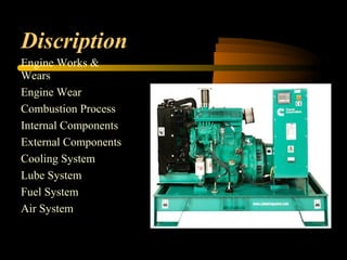
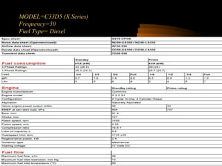
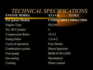
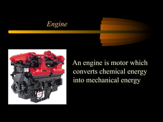
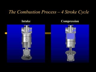
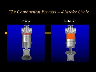
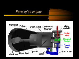
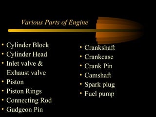
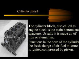
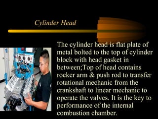
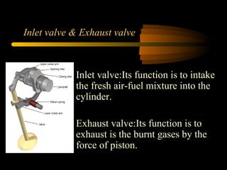
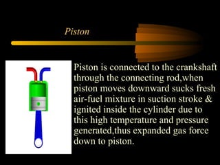
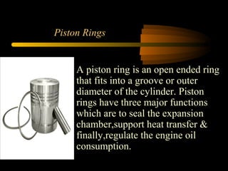
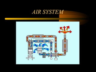
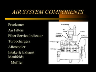
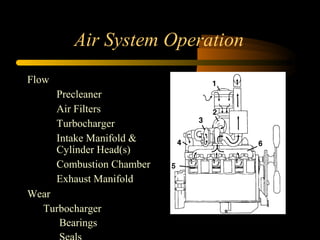
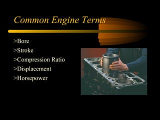
INTRODUTION:-
NAME = BILAL AHMAD
Designation= SERVICE ENGINEER
Department= Product Support Desiel Engine
Company= Orient energy system pvt. limitid
Discription
Engine Works &
Wears
Engine Wear
Combustion Process
Internal Components
External Components
Cooling System
Lube System
Fuel System
Air System
MODEL=C33D5 (X Series)
Frequency=50
Fuel Type= Diesel
Genset Data Sheet
TECHNICAL SPECIFICATIONS
ENGINE MODEL
For genset Models
Engine Type
No. Of Cylinder
Compression Ratio
Firing Order
Cycle of operation
Combustion system
Fuel pump
Governing
Cooling
X3.3 GI, X3.3G2
C33D5,C38D5 C30D6,C35D6
INLINE
4
18.5:2
1-3-4-2
Four Stroke
Direct Injection
BOSCH IN-LINE
Mechanical
Water cooled
Engine
An engine is motor which
converts chemical energy
into mechanical energy
Combustion Process
The Combustion Process – 4 Stroke Cycle
Intake Compression
The Combustion Process – 4 Stroke Cycle
Power Exhaust
Internal Components
Parts of an engine
Various Parts of Engine
• Crankshaft
• Crankcase
• Crank Pin
• Camshaft
• Spark plug
• Fuel pump
• Cylinder Block
• Cylinder Head
• Inlet valve &
Exhaust valve
• Piston
• Piston Rings
• Connecting Rod
• Gudgeon Pin
Cylinder Block
The cylinder block, also called as
engine block is the main bottom end
structure. Usually it is made up of
iron or aluminum.
Function: In the bore of the cylinder
the fresh charge of air-fuel mixture
is ignited,compressed by piston.
Cylinder Head
The cylinder head is flat plate of
metal bolted to the top of cylinder
block with head gasket in
between;Top of head contains
rocker arm & push rod to transfer
rotational mechanic from the
crankshaft to linear mechanic to
operate the valves. It is the key to
performance of the internal
combustion chamber.
Inlet valve & Exhaust valve
Inlet valve:Its function is to intake
the fresh air-fuel mixture into the
cylinder.
Exhaust valve:Its function is to
exhaust is the burnt gases by the
force of piston.
Piston
Piston is connected to the crankshaft
through the connecting rod,when
piston moves downward sucks fresh
air-fuel mixture in suction stroke &
ignited inside the cylinder due to
this high temperature and pressure
generated,thus expanded gas force
down to piston.
Piston Rings
A piston ring is an open ended ring
that fits into a groove or outer
diameter of the cylinder. Piston
rings have three major functions
which are to seal the expansion
chamber,support heat transfer &
finally,regulate the engine oil
consumption.
Connecting Rod & Gudgeon Pin
A small end of connecting rod is
connected to the piston and other
end is connected to the crankshaft.
Its function is to transmit the
reciprocating motion of piston to the
to the rotary motion of crankshaft.
Gudgeon pin is used to connect the
piston & connecting rod.
Crankshaft
Crankshaft is the part of an engine
which translates the reciprocating
linear motion of piston into
rotation. To convert the
reciprocating motion into
rotation,the crankshaft has “crank
pin”,it typically connects to
flywheel,to reduce the pulsation
characteristics four stroke cycle.
Camshaft
Camshaft is a part which is used in
piston engine to operate valves. It
consists of cylindrical rod with
cams. The camshaft were invented
in Iraq (Mesopotamia), described
by Al-Jazari in 1206.The
relationship between camshaft
rotation & crankshaft rotation is of
critical importance.
External components
Turbocharger
An exhaust driven air
compressor
Impeller on the left
Turbine on the right
Connecting shaft, free
floating
bearings, oil lubricated
center housing
Aftercooling
Heat exchanger for inlet air
Series of metal tubes through
which hot inlet air flows
Heat from the air flowing from
the tubes is absorbed through
the tube walls and carried away
2 types
Air to air (ATAAC)
Jacket water (JWAC)
Water Pump
Flow of the coolant begins
at the water pump
Water pumps are gear or
belt driven
Water pump seals
Separates engine oil from
coolant
OIL COOLER
FUEL SYSTEM
Types of fuel system
PT = PRESSURE TIME
IFSM =INTIGRATED FUEL SYSTEM MODULE
CRS= COMMON RAIL SYSTEM
MCRS= MODULAR COMMON RAIL
SYSTEM
CAPS=COMMON ACCUMOLATED PUMPING SYSTEM
HPI=HIGH PRESSURE INJECTION SYSTEM
ININE= INJECTION
ROTARY= INJECTION
FUEL SYSTEM DIAGRAM
FLOW DIAGRAM,FUEL SYSTEM
1.FUEL FROM SUPPLY TANK
2.FUEL LIFT PUMP
3.FUEL FILTER/WATER SEPARATOR
4.LOW-PRESSURE FUEL SUPPLY LINES
5.BOSCH@ KKSB COLD START INJECTION
ADVANCE
6.Bosch@ VE INJECTION PUMP
7.FUEL DRAIN MANIFOLD
8.HIGH PRESSURE FUEL SUPPLY LINES
9.BOSCH@ CLOSED NOZZLE INJECTORS
10.FUEL RETURN TO SUPPLY TANKS
AIR INTAKE SYSTEM
AIR SYSTEM
AIR SYSTEM COMPONENTS
Precleaner
Air Filters
Filter Service Indicator
Turbochargers
Aftercooler
Intake & Exhaust
Manifolds
Muffler
Air System Operation
Flow
1. Precleaner
2. Air Filters
3. Turbocharger
4. Intake Manifold &
Cylinder Head(s)
5. Combustion Chamber
6. Exhaust Manifold
Wear
Turbocharger
Bearings
Common Engine Terms
Common Engine Terms
>Bore
>Stroke
>Compression Ratio
>Displacement
>Horsepower
Bore Size
>The diameter of the
cylinder
>Measured in inches or
millimeters
Stroke
>How far the piston
moves from TDC to
BDC
>Equal to twice the
crank radius
Compression Ratio
Compression Ratio
> Ratio between the
cylinder volume with the
piston at BDC and the
volume with the piston
at TDC Compression
ratio of our engines are
approximately a 16:1
(non-ACERT) and 18:1
(ACERT)
Compression Ratio
Compression Ratio
> Ratio between the
cylinder volume with the
piston at BDC and the
volume with the piston
at TDC Compression
ratio of our engines are
approximately a 16:1
(non-ACERT) and 18:1
(ACERT)
Displacement
Engine size is expressed
in liters or cubic inches
Displacement = X Stroke X No. of Cyls.
(3.14 X B 2
)
4
Horsepower
Horsepower is the rate of doing work (how
quickly a force is applied through a distance)
Horsepower can be expressed in pound feet per
second
1 horsepower = 550 lb/ft per second
= 33,000 lb/ft per
minute
THANKS YOU

Presentaion engine

  • 3.
    INTRODUTION:- NAME = BILALAHMAD Designation= SERVICE ENGINEER Department= Product Support Desiel Engine Company= Orient energy system pvt. limitid
  • 4.
    Discription Engine Works & Wears EngineWear Combustion Process Internal Components External Components Cooling System Lube System Fuel System Air System
  • 5.
  • 6.
  • 7.
    TECHNICAL SPECIFICATIONS ENGINE MODEL Forgenset Models Engine Type No. Of Cylinder Compression Ratio Firing Order Cycle of operation Combustion system Fuel pump Governing Cooling X3.3 GI, X3.3G2 C33D5,C38D5 C30D6,C35D6 INLINE 4 18.5:2 1-3-4-2 Four Stroke Direct Injection BOSCH IN-LINE Mechanical Water cooled
  • 8.
    Engine An engine ismotor which converts chemical energy into mechanical energy
  • 9.
  • 10.
    The Combustion Process– 4 Stroke Cycle Intake Compression
  • 11.
    The Combustion Process– 4 Stroke Cycle Power Exhaust
  • 12.
  • 13.
  • 14.
    Various Parts ofEngine • Crankshaft • Crankcase • Crank Pin • Camshaft • Spark plug • Fuel pump • Cylinder Block • Cylinder Head • Inlet valve & Exhaust valve • Piston • Piston Rings • Connecting Rod • Gudgeon Pin
  • 15.
    Cylinder Block The cylinderblock, also called as engine block is the main bottom end structure. Usually it is made up of iron or aluminum. Function: In the bore of the cylinder the fresh charge of air-fuel mixture is ignited,compressed by piston.
  • 16.
    Cylinder Head The cylinderhead is flat plate of metal bolted to the top of cylinder block with head gasket in between;Top of head contains rocker arm & push rod to transfer rotational mechanic from the crankshaft to linear mechanic to operate the valves. It is the key to performance of the internal combustion chamber.
  • 17.
    Inlet valve &Exhaust valve Inlet valve:Its function is to intake the fresh air-fuel mixture into the cylinder. Exhaust valve:Its function is to exhaust is the burnt gases by the force of piston.
  • 18.
    Piston Piston is connectedto the crankshaft through the connecting rod,when piston moves downward sucks fresh air-fuel mixture in suction stroke & ignited inside the cylinder due to this high temperature and pressure generated,thus expanded gas force down to piston.
  • 19.
    Piston Rings A pistonring is an open ended ring that fits into a groove or outer diameter of the cylinder. Piston rings have three major functions which are to seal the expansion chamber,support heat transfer & finally,regulate the engine oil consumption.
  • 20.
    Connecting Rod &Gudgeon Pin A small end of connecting rod is connected to the piston and other end is connected to the crankshaft. Its function is to transmit the reciprocating motion of piston to the to the rotary motion of crankshaft. Gudgeon pin is used to connect the piston & connecting rod.
  • 21.
    Crankshaft Crankshaft is thepart of an engine which translates the reciprocating linear motion of piston into rotation. To convert the reciprocating motion into rotation,the crankshaft has “crank pin”,it typically connects to flywheel,to reduce the pulsation characteristics four stroke cycle.
  • 22.
    Camshaft Camshaft is apart which is used in piston engine to operate valves. It consists of cylindrical rod with cams. The camshaft were invented in Iraq (Mesopotamia), described by Al-Jazari in 1206.The relationship between camshaft rotation & crankshaft rotation is of critical importance.
  • 23.
  • 24.
    Turbocharger An exhaust drivenair compressor Impeller on the left Turbine on the right Connecting shaft, free floating bearings, oil lubricated center housing
  • 25.
    Aftercooling Heat exchanger forinlet air Series of metal tubes through which hot inlet air flows Heat from the air flowing from the tubes is absorbed through the tube walls and carried away 2 types Air to air (ATAAC) Jacket water (JWAC)
  • 26.
    Water Pump Flow ofthe coolant begins at the water pump Water pumps are gear or belt driven Water pump seals Separates engine oil from coolant
  • 27.
  • 28.
  • 29.
    Types of fuelsystem PT = PRESSURE TIME IFSM =INTIGRATED FUEL SYSTEM MODULE CRS= COMMON RAIL SYSTEM MCRS= MODULAR COMMON RAIL SYSTEM CAPS=COMMON ACCUMOLATED PUMPING SYSTEM HPI=HIGH PRESSURE INJECTION SYSTEM ININE= INJECTION ROTARY= INJECTION
  • 30.
  • 31.
    FLOW DIAGRAM,FUEL SYSTEM 1.FUELFROM SUPPLY TANK 2.FUEL LIFT PUMP 3.FUEL FILTER/WATER SEPARATOR 4.LOW-PRESSURE FUEL SUPPLY LINES 5.BOSCH@ KKSB COLD START INJECTION ADVANCE 6.Bosch@ VE INJECTION PUMP 7.FUEL DRAIN MANIFOLD 8.HIGH PRESSURE FUEL SUPPLY LINES 9.BOSCH@ CLOSED NOZZLE INJECTORS 10.FUEL RETURN TO SUPPLY TANKS
  • 32.
  • 33.
  • 34.
    AIR SYSTEM COMPONENTS Precleaner AirFilters Filter Service Indicator Turbochargers Aftercooler Intake & Exhaust Manifolds Muffler
  • 35.
    Air System Operation Flow 1.Precleaner 2. Air Filters 3. Turbocharger 4. Intake Manifold & Cylinder Head(s) 5. Combustion Chamber 6. Exhaust Manifold Wear Turbocharger Bearings
  • 36.
    Common Engine Terms CommonEngine Terms >Bore >Stroke >Compression Ratio >Displacement >Horsepower
  • 37.
    Bore Size >The diameterof the cylinder >Measured in inches or millimeters
  • 38.
    Stroke >How far thepiston moves from TDC to BDC >Equal to twice the crank radius
  • 39.
    Compression Ratio Compression Ratio >Ratio between the cylinder volume with the piston at BDC and the volume with the piston at TDC Compression ratio of our engines are approximately a 16:1 (non-ACERT) and 18:1 (ACERT)
  • 40.
    Compression Ratio Compression Ratio >Ratio between the cylinder volume with the piston at BDC and the volume with the piston at TDC Compression ratio of our engines are approximately a 16:1 (non-ACERT) and 18:1 (ACERT)
  • 41.
    Displacement Engine size isexpressed in liters or cubic inches Displacement = X Stroke X No. of Cyls. (3.14 X B 2 ) 4
  • 42.
    Horsepower Horsepower is therate of doing work (how quickly a force is applied through a distance) Horsepower can be expressed in pound feet per second 1 horsepower = 550 lb/ft per second = 33,000 lb/ft per minute
  • 43.