Download to read offline
![Service Information
Document Title: Function Group: Information Type: Date:
Engine, description 200 Service Information 2014/4/1 0
Profile:
WLO, L60F [GB]
Engine, description
D6E
D6E is a straight six-cylinder, four-stroke, turbocharged diesel engine with direct injection and intercooler, as well as wet,
replaceable cylinder liners. The engine is equipped to meet governing legislation according to Tier 3/stage IIIA for exhaust
emissions.
Engine D6E has a fuel system with Common Rail, which is controlled by the software in the engine's electronic control unit
(E-ECU).
The D6E uses V-ACT (Volvo Advanced Combustion Technology). Engine D6EV with ACT features split injection, optimized air
handling and, turbocharger with wastegate. Electronically controlled IEGR (Internal Exhaust Gas Recirculation) reduces NO
contents and reduces emissions without the need for after-treatment of exhausts. All electronic functions in the engine are
controlled by Volvo's latest engine management system, EMS2.
The engine's serial number is stamped on the name plate, on the cylinder block's side and on the valve cover. The engine's
model designation and serial number must be indicated when ordering spare parts.
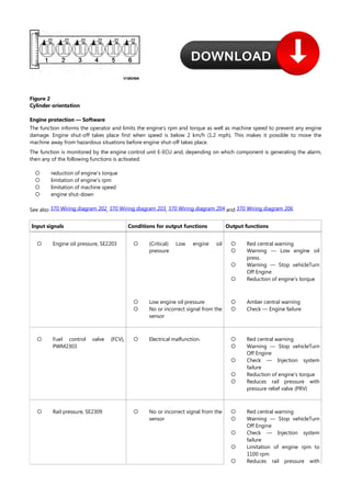
Figure 1
The cylinders are numbered in sequence, starting at the flywheel. Ignition order: 1-5-3-6-2-4. The engine's rotational
direction is counter-clockwise, seen from the flywheel.](https://image.slidesharecdn.com/volvol60fenginedescriptionservicemanual-260106091301-106b6509/85/Volvo-L60f-Engine-Description-Service-Manual-pdf-1-320.jpg)
![Service Information
Document Title: Function Group: Information Type: Date:
Engine, description 200 Service Information 2014/4/1 0
Profile:
WLO, L60F [GB]
Engine, description
D6E
D6E is a straight six-cylinder, four-stroke, turbocharged diesel engine with direct injection and intercooler, as well as wet,
replaceable cylinder liners. The engine is equipped to meet governing legislation according to Tier 3/stage IIIA for exhaust
emissions.
Engine D6E has a fuel system with Common Rail, which is controlled by the software in the engine's electronic control unit
(E-ECU).
The D6E uses V-ACT (Volvo Advanced Combustion Technology). Engine D6EV with ACT features split injection, optimized air
handling and, turbocharger with wastegate. Electronically controlled IEGR (Internal Exhaust Gas Recirculation) reduces NO
contents and reduces emissions without the need for after-treatment of exhausts. All electronic functions in the engine are
controlled by Volvo's latest engine management system, EMS2.
The engine's serial number is stamped on the name plate, on the cylinder block's side and on the valve cover. The engine's
model designation and serial number must be indicated when ordering spare parts.
Figure 1
The cylinders are numbered in sequence, starting at the flywheel. Ignition order: 1-5-3-6-2-4. The engine's rotational
direction is counter-clockwise, seen from the flywheel.](https://image.slidesharecdn.com/volvol60fenginedescriptionservicemanual-260106091301-106b6509/75/Volvo-L60f-Engine-Description-Service-Manual-pdf-1-2048.jpg)
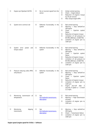
![This function monitors boost pressure and informs the operator if there is a system malfunction.
Engine speed is used internally in the E-ECU for engine control and as input signal for engine protection.
In case of engine speed sensor malfunction, the E-ECU uses sensor SE2703 for camshaft speed instead.
See also 370 Wiring diagram 202
Input signals Conditions for output functions Output functions
Monitoring,
SE2701
System malfunction, signal missing or abnormal
frequency
See Diagnostics
Amber central warning
Check — Engine system
failure
Reduction of engine's
torque I (engine
protection)
Motor On/Off — Software
Engine On/Off is used as a condition in software functions to define when the engine is considered to be On and Off,
respectively.
See also .
370 Wiring diagram 201
Input signals Conditions for output functions Output functions
Engine speed < 50 rpm Engine = Off
Engine speed,
SE2704
Engine speed > 600 rpm Engine = On
Automatic engine shutdown — Software
The function control engine shut-off when the conditions according to the table have been fulfilled, and informs the
operator that the engine will be shut off within 1 minute. When the engine is shut off the parking brake will also be applied.
The operator can interrupt engine shutdown by affecting the throttle pedal, hand throttle, or the gear selector.
See also , , and
370 Wiring diagram 201 370 Wiring diagram 205 370 Wiring diagram 404 370 Wiring diagram 408
Input signals Conditions for output functions Output functions
Overall conditions for the function
VCADS Pro parameter FAU "On"
VCADS Pro
parameter FAU
VCADS Pro
parameter FAV
Directional gear,
SW4205
Throttle pedal,
SE2702 APS
Hand throttle,
SE2701
Engine On/Off
Travel speed
1.
2.
3.
Activation of the
function automatic
engine shut-off (4–50
min.)
When 1 minute remains
of set time Check —
AutomaticEngine
shutdown is shown. [T1]
Engine shutdown and
parking brake is applied
(MA5501 without
voltage)
VCADS Pro parameter FAV "4–99 minutes"
Directional gear in position N
Accelerator pedal < 5%
Hand throttle not activated
Engine On
Travel speed < 5 km/h (3 mph)
[T1]Engine shutdown is interrupted in case of activation of throttle pedal, hand throttle, or if the gear selector is moved to
position F or R.
Increased engine speed — Software
The function prevents reduction of engine rpm in case of high power usage.](https://image.slidesharecdn.com/volvol60fenginedescriptionservicemanual-260106091301-106b6509/85/Volvo-L60f-Engine-Description-Service-Manual-pdf-5-320.jpg)
![Service Information
Document Title: Function Group: Information Type: Date:
E-ECU, MID 128, changing
non-programmed ECU
200 Service Information 2014/4/1 0
Profile:
WLO, L60F [GB]
E-ECU, MID 128, changing non-programmed ECU
Op nbr 200-068
VCADS Pro VCADS Pro Service Tool
88890180 Interface
88890027 Cable
1. Place the machine in service position 1, see .
191 Service position
2. Connect VCADS Pro and perform the operation 28423-3 MID 128 ECU, programming.
3. Open the engine hood on the left side.
4. Unplug connectors from the E-ECU and loosen the cable harness clamps.
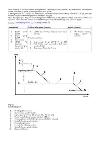
Figure 1
1.
2.
Connectors
Cable harness clamps
5. Change E-ECU.
6. Plug in the connectors for the E-ECU and install the cable harness clamps.
7. Turn on the voltage with the battery disconnector.
8. Finish VCADS Pro operation 28423-3 MID 128 ECU, programming.
9. Start the machine and check that no error messages appear.
10. Restore the machine to operating condition.](https://image.slidesharecdn.com/volvol60fenginedescriptionservicemanual-260106091301-106b6509/85/Volvo-L60f-Engine-Description-Service-Manual-pdf-7-320.jpg)
![Service Information
Document Title: Function Group: Information Type: Date:
E-ECU, MID 128, changing
pre-programmed ECU
200 Service Information 2014/4/1 0
Profile:
WLO, L60F [GB]
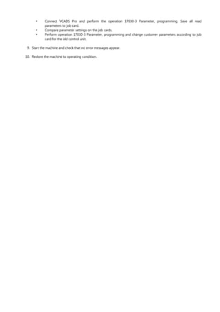
E-ECU, MID 128, changing pre-programmed ECU
Op nbr 200-070
VCADS Pro VCADS Pro Service Tool
88890180 Interface
88890027 Cable
1. Place the machine in service position 1, see .
191 Service position
2. The new control unit has basic set parameters for the machine. If it is possible to read out customer parameters,
connect VCADS Pro and perform the operation 17030-3 Parameter, programming. Save all read parameters to job
card.
The operation is used to read out customer parameters from the old control unit to enable later comparison with
parameters in the new control unit.
3. Open the engine hood on the left side.
4. Unplug connectors from the E-ECU and loosen the cable harness clamps.
Figure 1
1.
2.
Connectors
Cable harness clamps
5. Change E-ECU.
6. Plug in the connectors for the E-ECU and install the cable harness clamps.
7. Turn on the voltage with the battery disconnector.
8. If customer parameters have been read out from the old control unit, compare these to the parameters in the new
control unit.](https://image.slidesharecdn.com/volvol60fenginedescriptionservicemanual-260106091301-106b6509/85/Volvo-L60f-Engine-Description-Service-Manual-pdf-8-320.jpg)


The Volvo L60f Engine Description Service Manual.pdf The Volvo L60F Engine Description Service Manual provides detailed technical information on the D6E diesel engine used in the L60F wheel loader. It explains engine design features, including the straight six-cylinder layout, turbocharging, common-rail fuel injection, and emissions-compliant combustion technology. The manual describes key engine components, operating principles, electronic engine control unit (E-ECU) functions, and protective features that monitor sensors and adjust performance. This resource supports accurate service, diagnostic testing, and understanding of engine behavior for maintenance and repair tasks.


