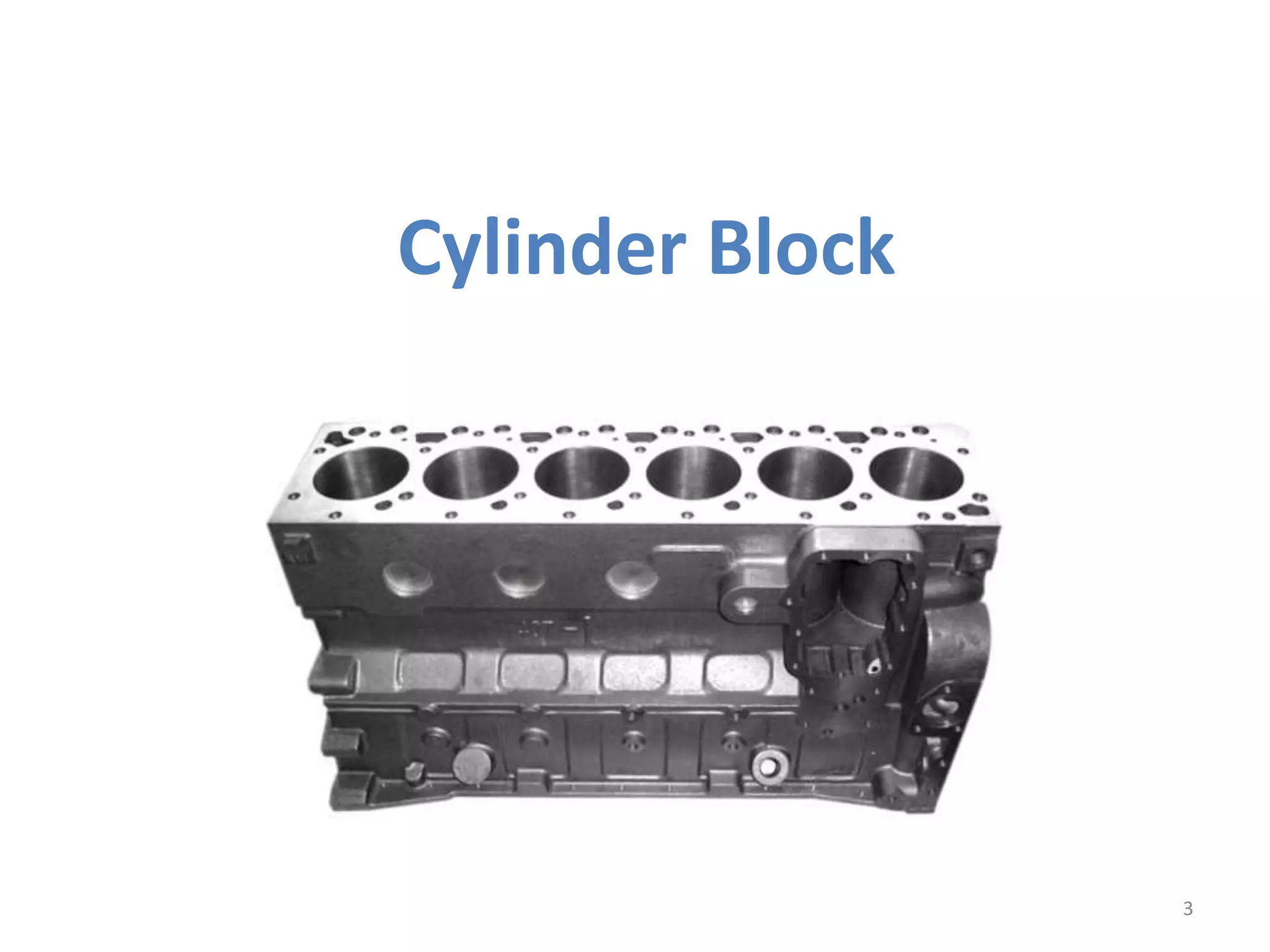
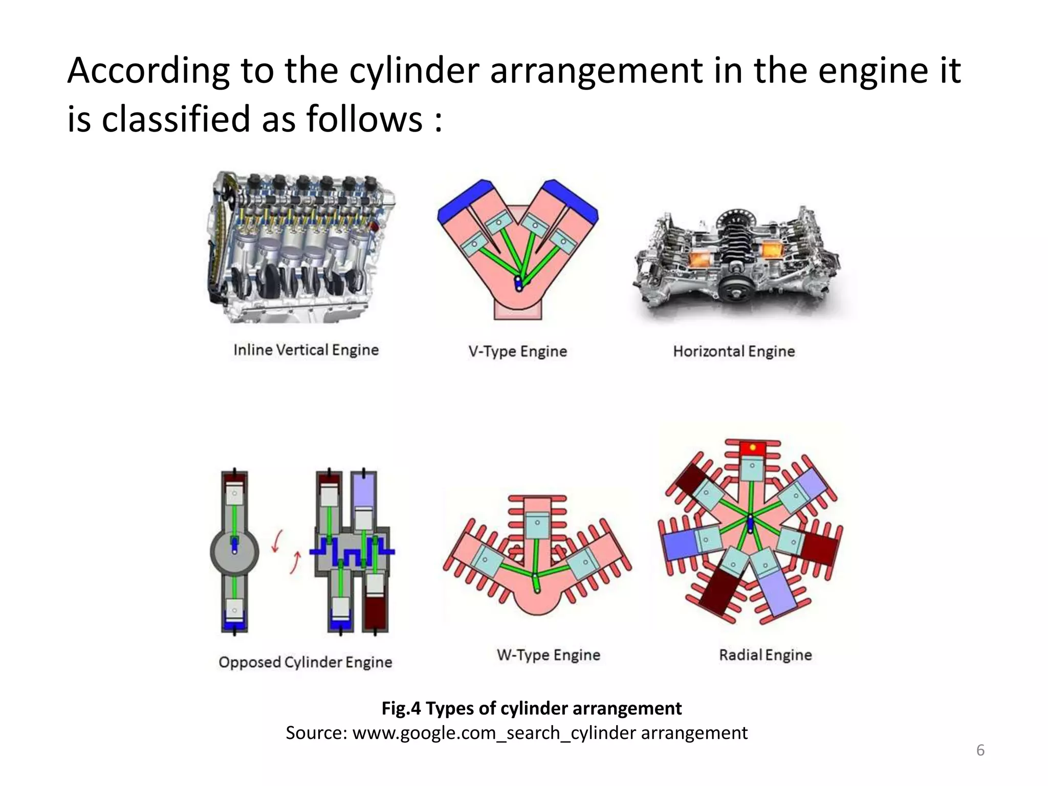
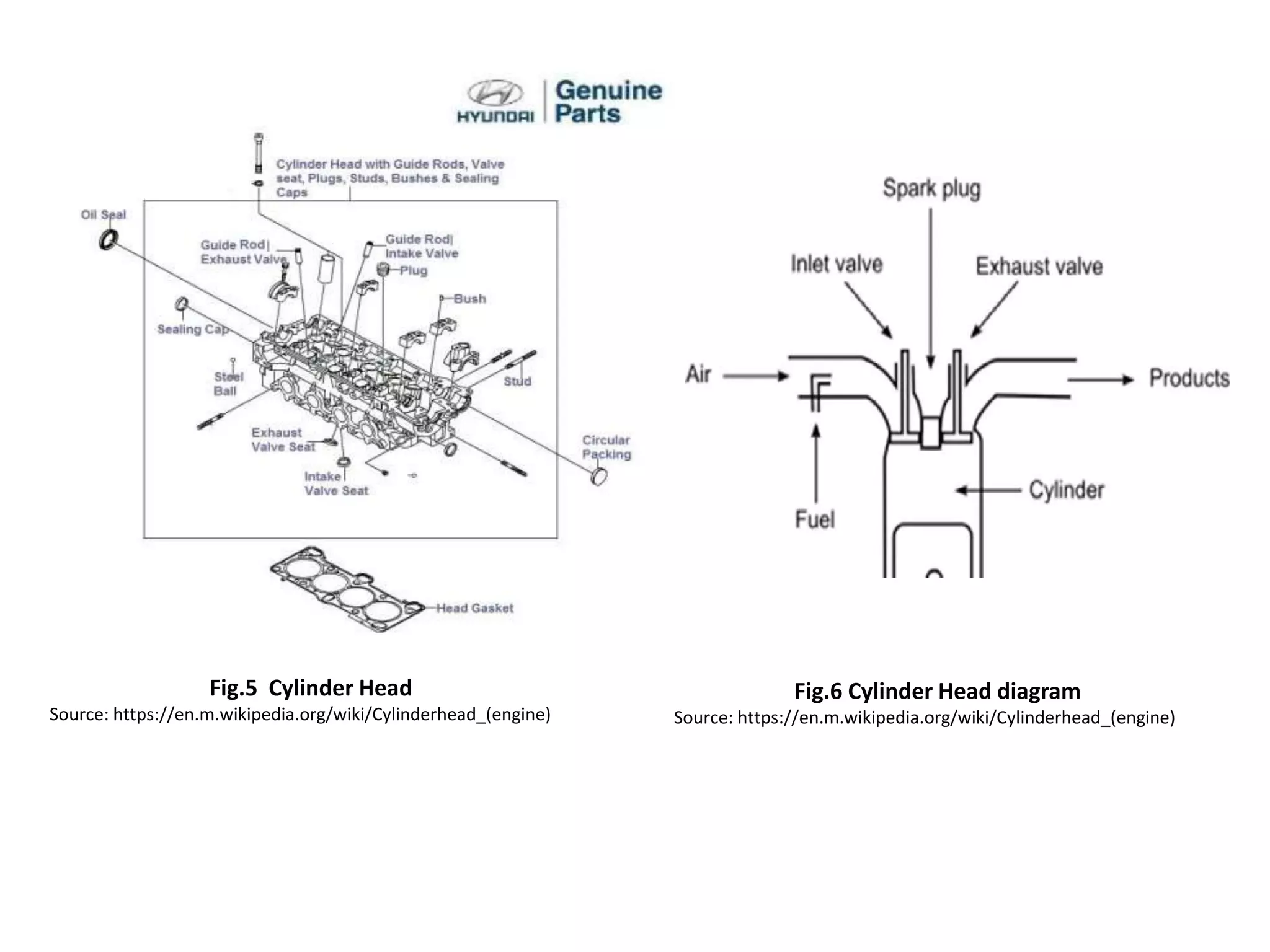
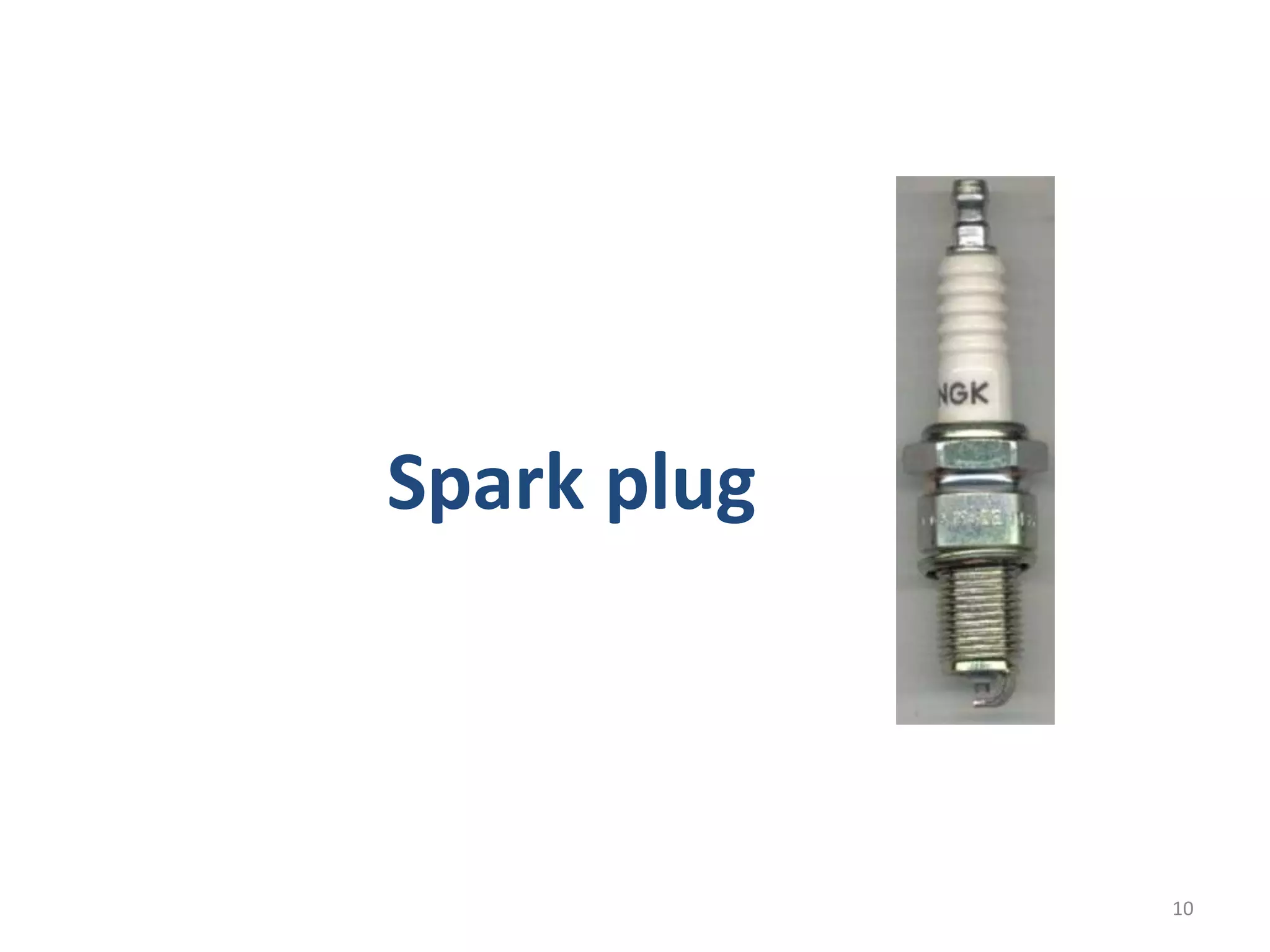
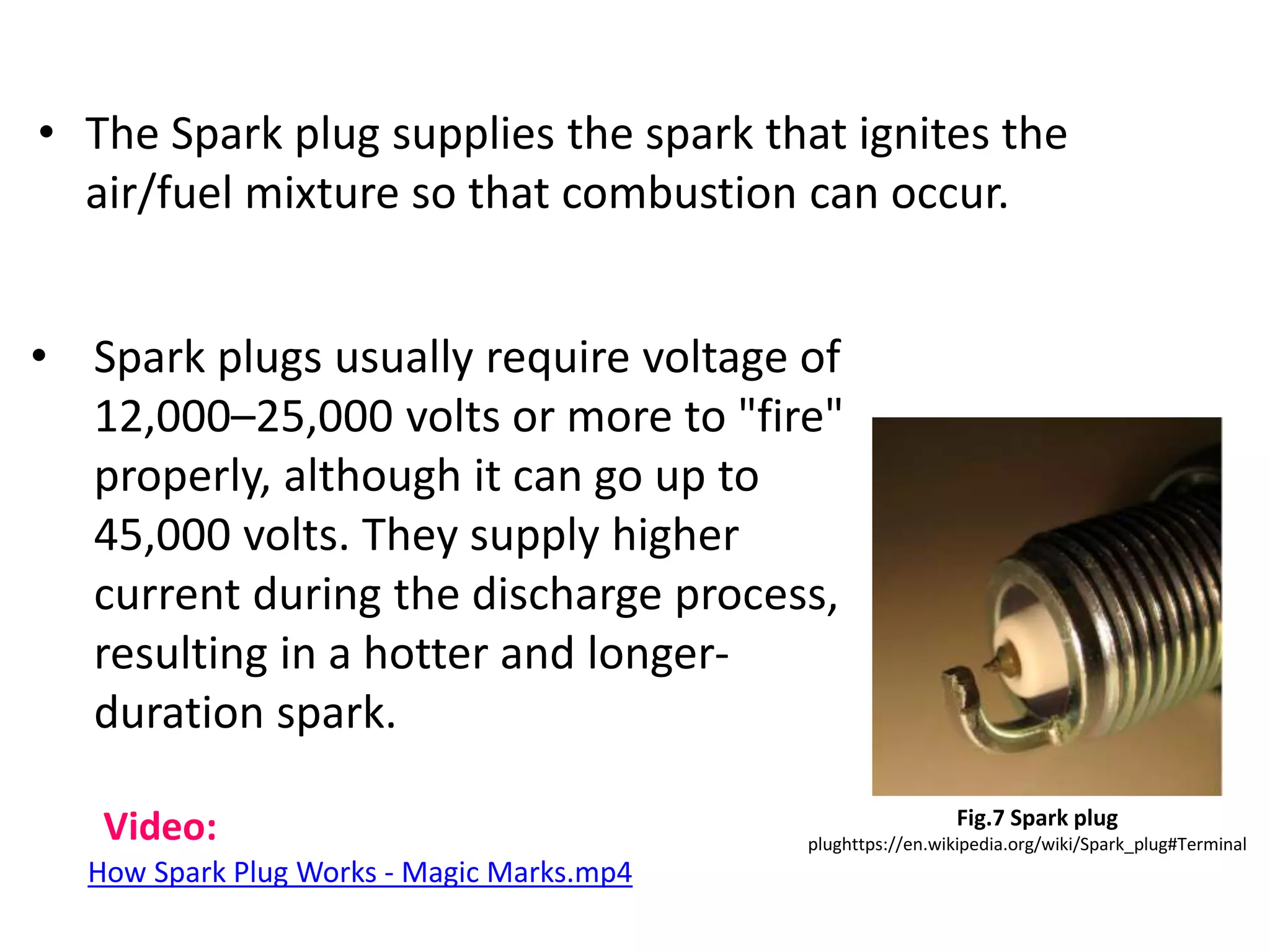
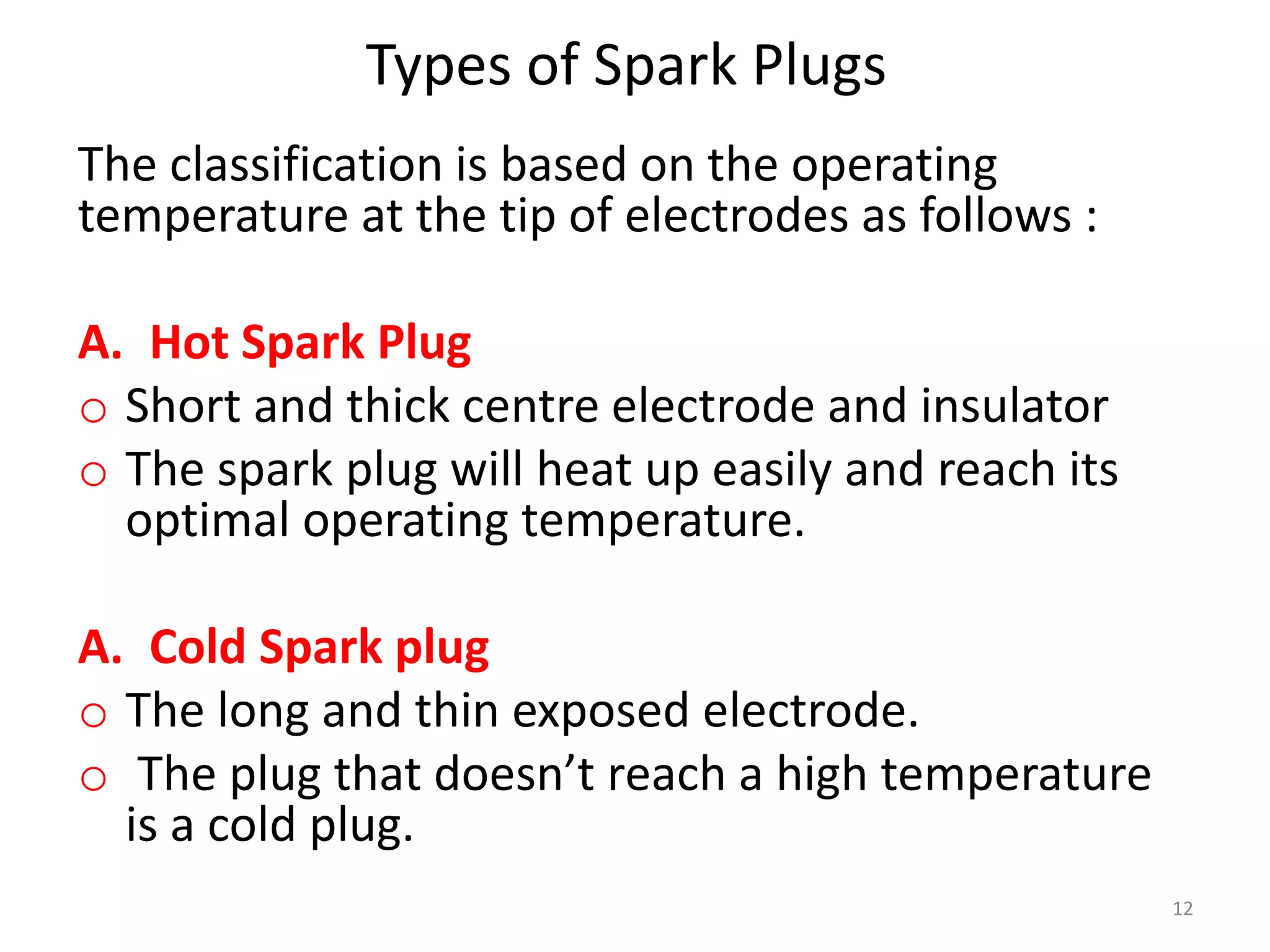
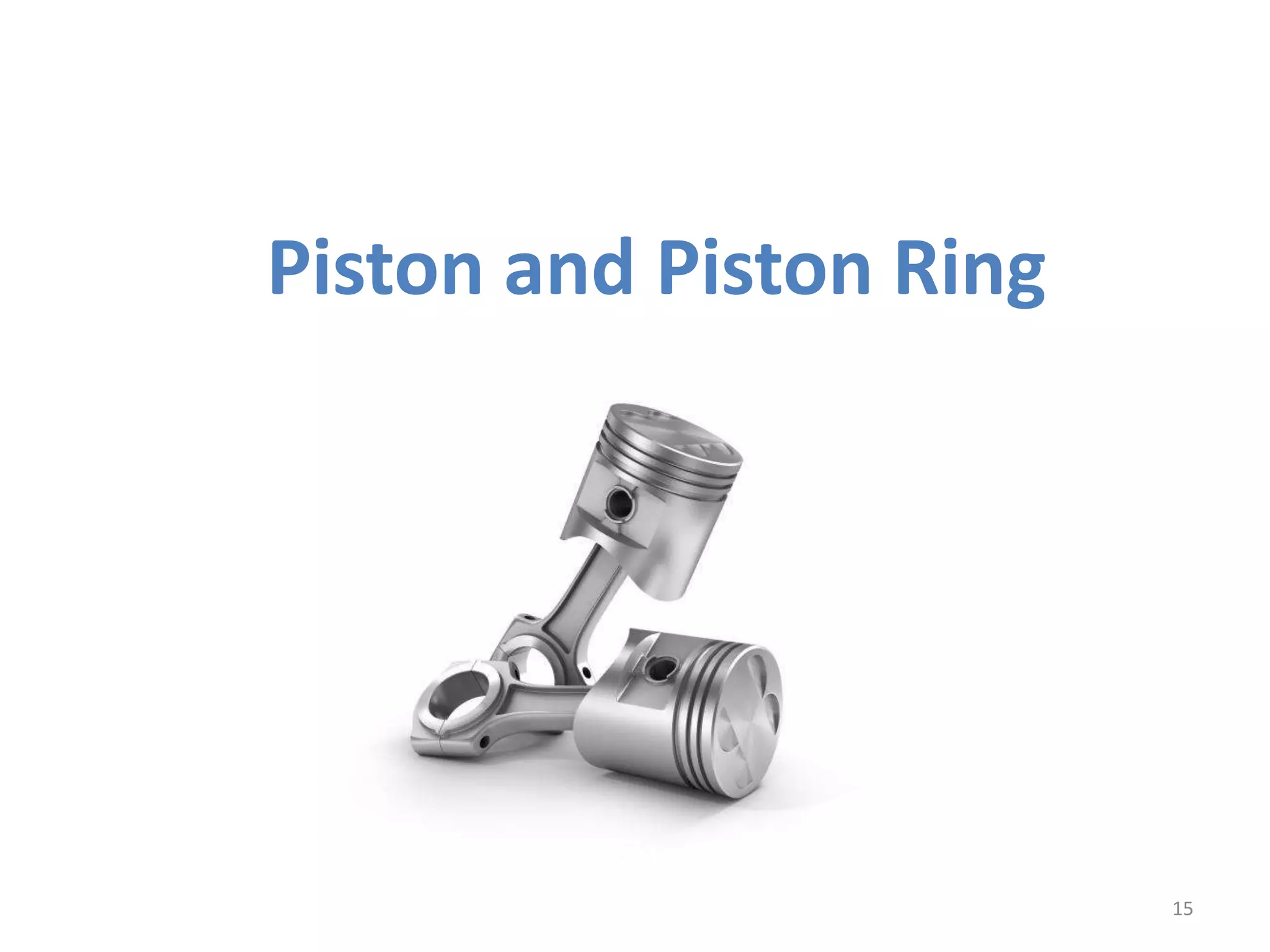
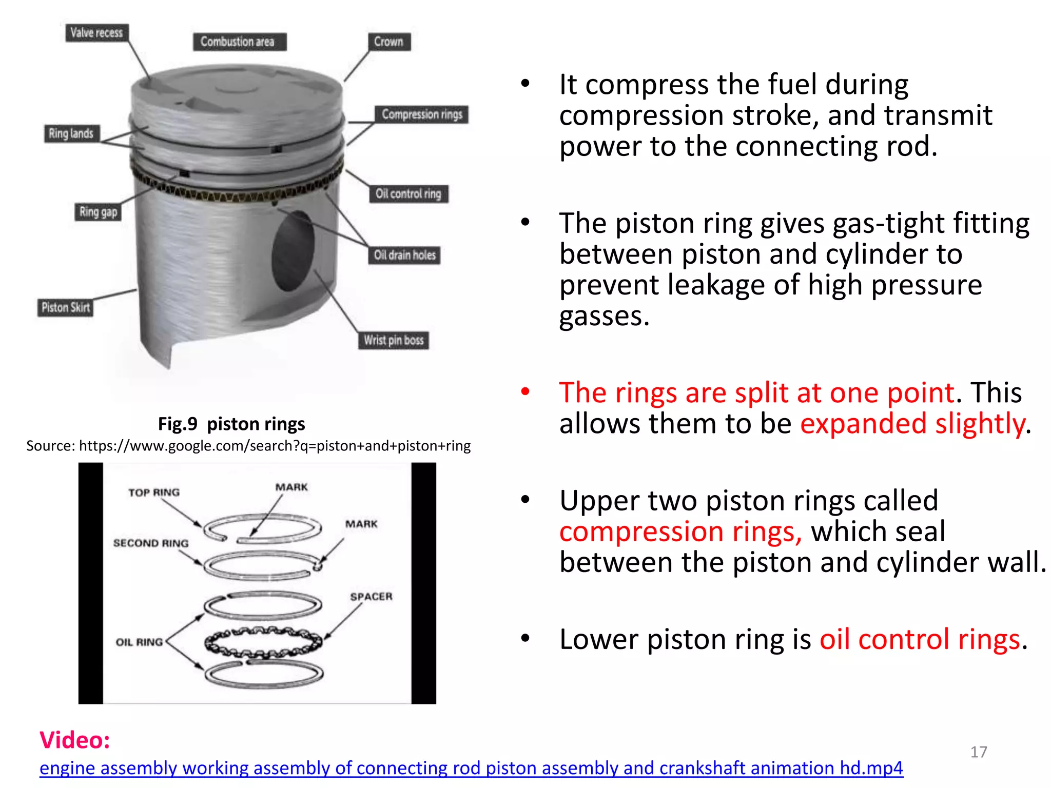
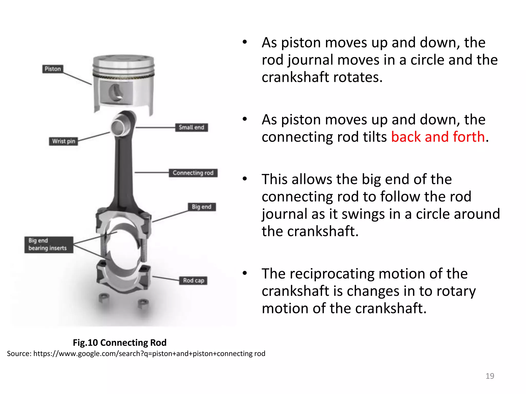
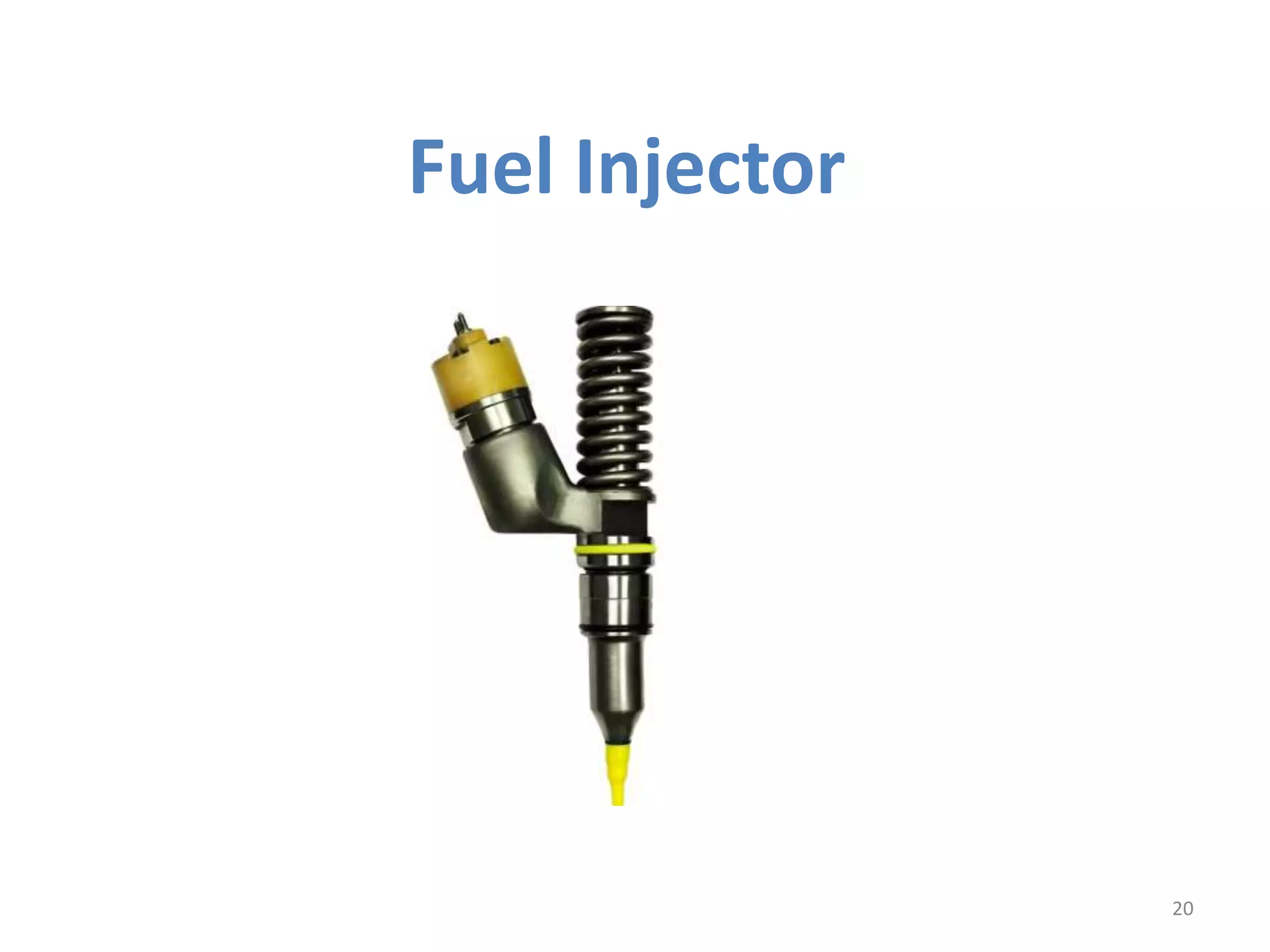
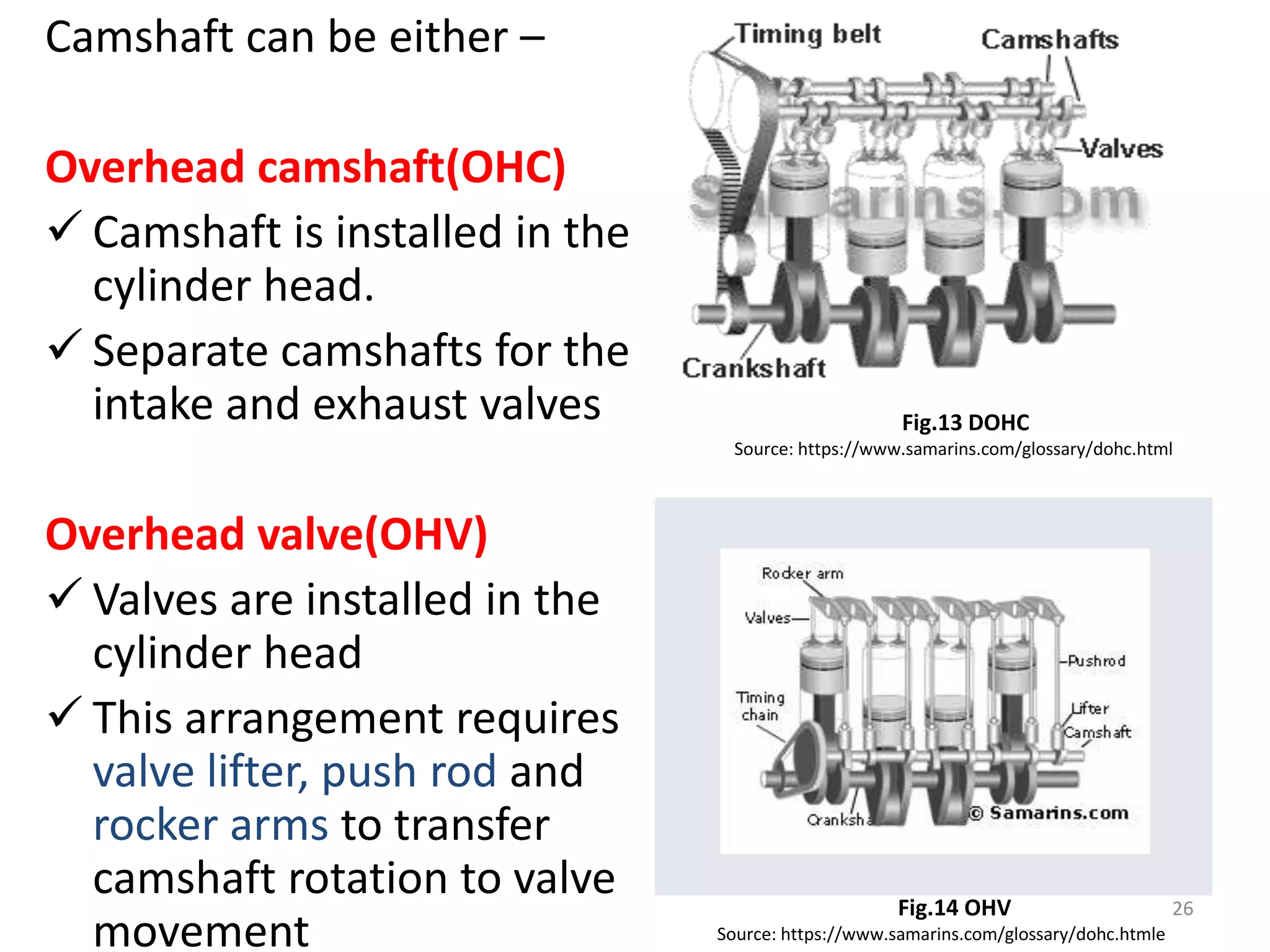
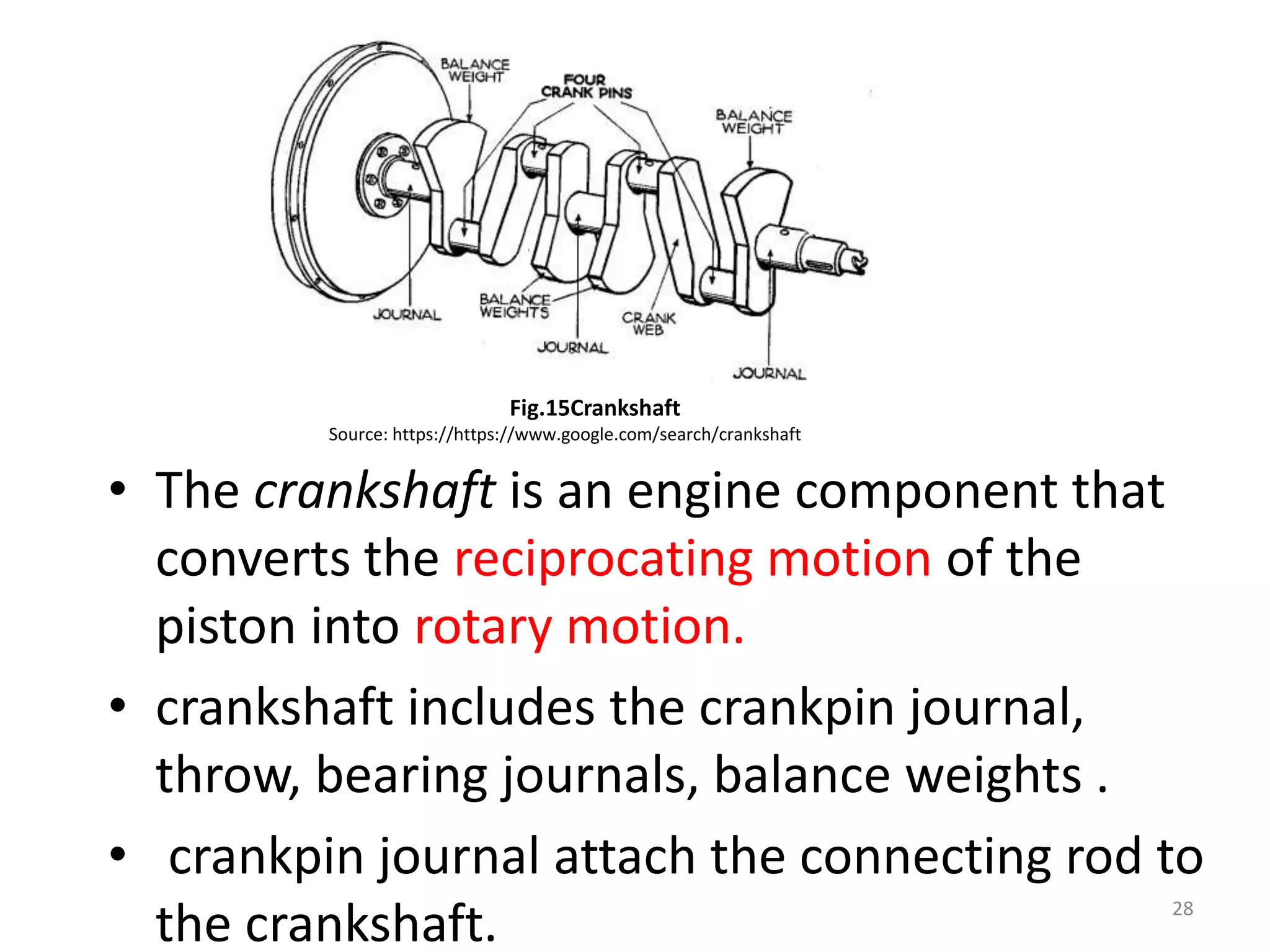
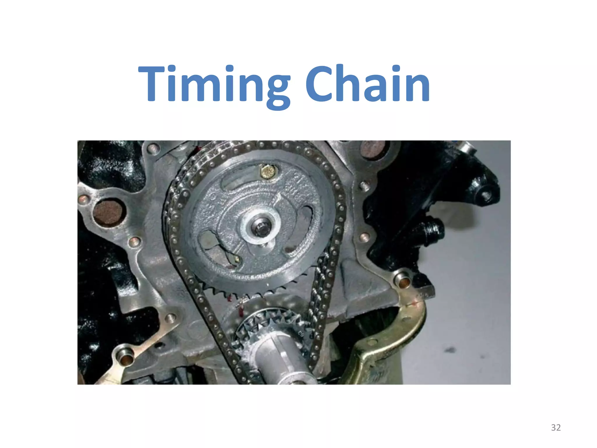
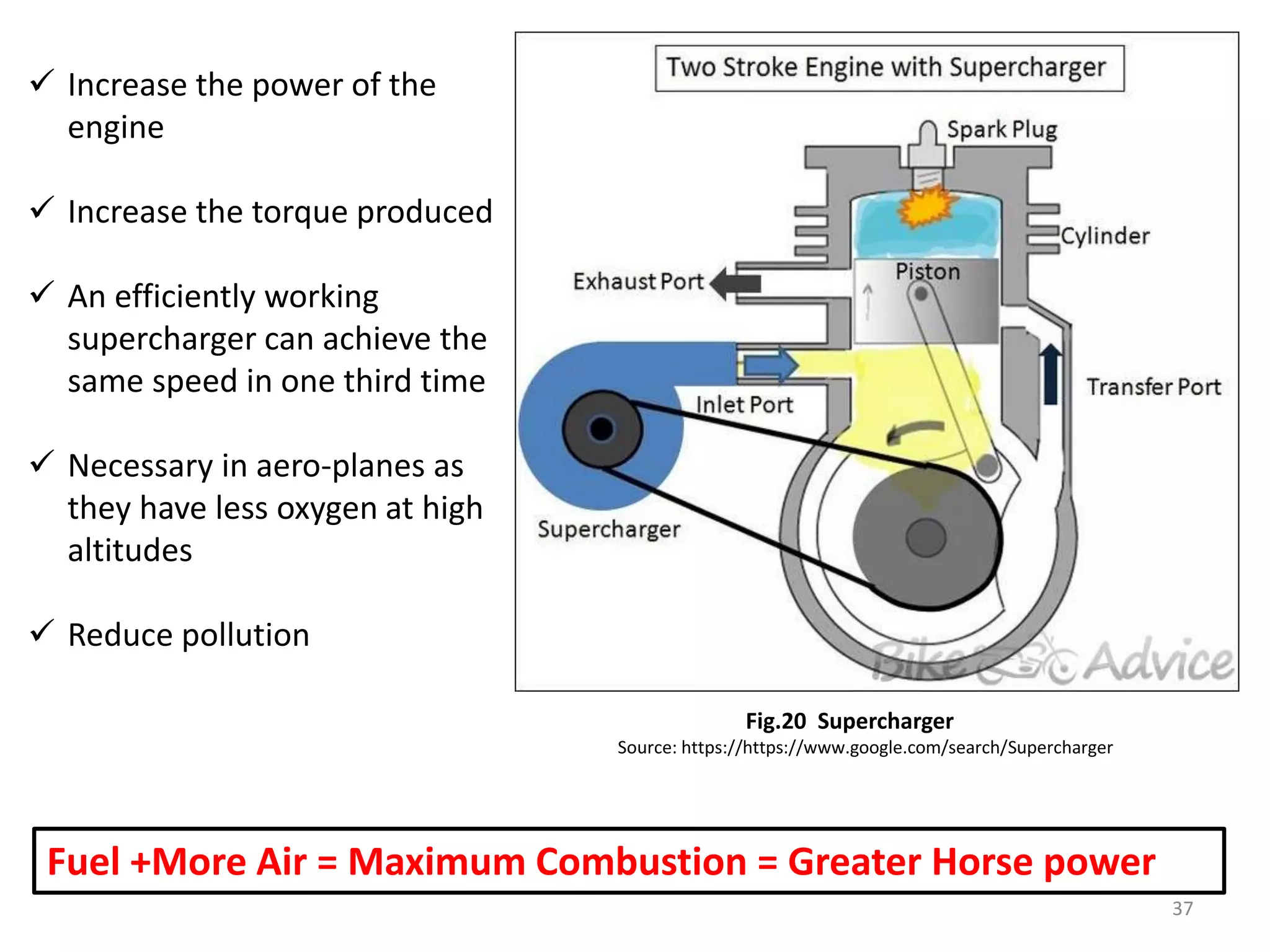
COMPONENTS OF AN I.C.
ENGINE
1
Pooja Shinde
ADAM ,Pune
12/03/2019
2
Fig.1 IC Engine
Source: https://www.google.com/search?safe=strict&tbm=isch&q=ic+engine+cut-section
Cylinder Block
3
• Cylinder block is a basic structure of the engine on that other
parts are involved.
• Block contain Bore ,piston ,gasket ,pumps and other
components are attached to it.
• It is made from the material aluminium alloyed, Grey cast
iron, white iron, Grey iron. 4
Fig.2 cylinder block
https://en.m.wikipedia.org/wiki/Cylinderblock_(engine)
• A cylinder is the central working part of reciprocating engine,
the space in which a piston travels.
• Cylinders may be sleeved (lined with a harder metal)
or sleeveless (with a wear-resistant coating such as Nikasil). A
sleeveless engine may also be referred to as a "parent-bore
engine".
• Cylinder also consist of Inlets for the coolant to keep them
cool during the combustion process. 5
Fig.3 Cycles inside the cylinder
https://en.m.wikipedia.org/wiki/Cylinder_(engine)
6
According to the cylinder arrangement in the engine it
is classified as follows :
Fig.4 Types of cylinder arrangement
Source: www.google.com_search_cylinder arrangement
Cylinder Head
7
8
Fig.5 Cylinder Head
Source: https://en.m.wikipedia.org/wiki/Cylinderhead_(engine)
Fig.6 Cylinder Head diagram
Source: https://en.m.wikipedia.org/wiki/Cylinderhead_(engine)
• In an IC engine, the cylinder head sits above
the cylinders. It closes in the top of the cylinder.
• This joint is sealed by a head gasket to avoid the
leakaging of gases.
• In most engines, the head also provides space for the
passages that feed air and fuel to the cylinder, and that
allow the exhaust to escape.
• The head can also be a place to mount the valves ,spark
plugs, Studs, Bushes and fuel injectors.
9
Spark plug
10
• The Spark plug supplies the spark that ignites the
air/fuel mixture so that combustion can occur.
Fig.7 Spark plug
plughttps://en.wikipedia.org/wiki/Spark_plug#Terminal
• Spark plugs usually require voltage of
12,000–25,000 volts or more to "fire"
properly, although it can go up to
45,000 volts. They supply higher
current during the discharge process,
resulting in a hotter and longer-
duration spark.
Video:
How Spark Plug Works - Magic Marks.mp4
Types of Spark Plugs
The classification is based on the operating
temperature at the tip of electrodes as follows :
A. Hot Spark Plug
o Short and thick centre electrode and insulator
o The spark plug will heat up easily and reach its
optimal operating temperature.
A. Cold Spark plug
o The long and thin exposed electrode.
o The plug that doesn’t reach a high temperature
is a cold plug.
12
What happens when a plug is too cold?
• If the nose of the plug is not hot enough, it will gradually
accumulate deposits, known as fouling.
• During normal engine operation, residue from the combustion
process hits the insulator nose.
• If the insulator nose and electrodes are hot enough, the
combustion deposits on the electrode.
• Hence at too cold condition, the efficiency of the spark plug
decreases.
13
What happens when spark plug is too
hot?
• When a spark plug gets too hot, the insulator may boil and
bubble On examination, it will be plain that it has been too
hot.
• A too-hot plug that fails to destroy itself is when it destroys
the engine instead; this is called pre-ignition.
• If the tip of the plug becomes hot enough to ignite the fresh
mixture being drawn into the cylinder, then the incoming
mixture will start to burn without waiting for the spark to
happen.
• early ignition makes engines heat up, causing pre-ignition.
Eventually, melting of the parts happens.
• Hence at too hot condition, the efficiency of the spark plug
decreases.
14
Piston and Piston Ring
15
16
Fig.8 piston with rings
Source: https://www.google.com/search?q=piston+and+piston+ring
• Pistons are made up of aluminum alloy.
• Piston slightly smaller than the cylinder which allows
the piston to slide up and down that is in reciprocating
motion this is sliding fit.
• It compress the fuel during
compression stroke, and transmit
power to the connecting rod.
• The piston ring gives gas-tight fitting
between piston and cylinder to
prevent leakage of high pressure
gasses.
• The rings are split at one point. This
allows them to be expanded slightly.
• Upper two piston rings called
compression rings, which seal
between the piston and cylinder wall.
• Lower piston ring is oil control rings.
17
Fig.9 piston rings
Source: https://www.google.com/search?q=piston+and+piston+ring
Video:
engine assembly working assembly of connecting rod piston assembly and crankshaft animation hd.mp4
Connecting Rod
18
• As piston moves up and down, the
rod journal moves in a circle and the
crankshaft rotates.
• As piston moves up and down, the
connecting rod tilts back and forth.
• This allows the big end of the
connecting rod to follow the rod
journal as it swings in a circle around
the crankshaft.
• The reciprocating motion of the
crankshaft is changes in to rotary
motion of the crankshaft.
19
Fig.10 Connecting Rod
Source: https://www.google.com/search?q=piston+and+piston+connecting rod
Fuel Injector
20
• The mixing of air and fuel depends on the
induction swirl provided by directing the flow of
air in desired direction through ports
• Nozzle is the part of the injector through which
fuel is injected to combustion chamber. There are
single hole, multiple hole,pintle and pintaux
types.
• The actual mixing of air and fuel achieved by
injecting fuel in the chamber through a nozzle
under pressure more than 200 bar.
21
Valves
22
23
• Most engines have two ports, one is intake port, other is
exhaust port.
• When valve moves up in to its port, in this position valve is
closed.
• When valve is pushed down off its seat, the port is open.
Then the air fuel mixture can pass through the port.
• The opening and closing of the valves are controlled by the
valve train or Camshaft.
Fig.11 Cam Lobe
Source: https://www.google.com/search?lobe
Camshaft
24
• Camshaft decides the opening and the closing of the intake and
exhaust valves.
• Cams are raised oval shaped section of a shaft that is called as
Lobes.
• Lobes decides when valve will open.
• As the camshaft rotates, the lobes rotates and push the valve open
or close.
25
Fig.12 Cam Lobe
Source: https://www.google.com/search?lobe
Camshaft can be either –
Overhead camshaft(OHC)
 Camshaft is installed in the
cylinder head.
 Separate camshafts for the
intake and exhaust valves
Overhead valve(OHV)
 Valves are installed in the
cylinder head
 This arrangement requires
valve lifter, push rod and
rocker arms to transfer
camshaft rotation to valve
movement
26Fig.14 OHV
Source: https://www.samarins.com/glossary/dohc.htmle
Fig.13 DOHC
Source: https://www.samarins.com/glossary/dohc.html
crankshaft
27
• The crankshaft is an engine component that
converts the reciprocating motion of the
piston into rotary motion.
• crankshaft includes the crankpin journal,
throw, bearing journals, balance weights .
• crankpin journal attach the connecting rod to
the crankshaft. 28
Fig.15Crankshaft
Source: https://https://www.google.com/search/crankshaft
• The crank throw is the
measurement from the
centre of the crankshaft
to the centre of the
crankpin journal.
• used to determine the
stroke of an engine.
• The longer the throw, the
greater the stroke, or
piston travels.
29
Fig.16 crank throw
Source: https://https://www.google.com/search/crankthrow
Flywheel
30
• A flywheel is a mechanical device specifically designed to
efficiently store rotational energy.
• The piston moves by the pressure produce during combustion
,but the moves the piston only about half a stroke or one
quarter of revolution of the crankshaft.
• The flywheel stores some of the power produced by the engine.
31
• The power is used to keep the
piston in motion during rest of the
four-stroke cycle.
Video:
How Flywheel Works_ - Magic Marks - YouTube (360p).mp4
Fig.17 Flywheel in the machine
Source: https://https://www.google.com/search/flywheel
Timing Chain
32
• It synchronizes the rotation of the crankshaft and the camshaft(s) so that the
engine's valves open and close at the proper time.
• Higher torque engines that do a lot of heavy work, are usually equipped with
timing chains. Trucks and heavy duty vehicles are usually equipped with timing
chains to deliver more power.
• Rubber timing belts are found in the majority of small cars and SUVs,
particularly 4 cylinder engines that have lower torque.
33
Video:
Timing Chain - YouTube (360p).mp4
Fig.18 Flywheel mechanism
Source: https://https://www.google.com/search/Flywheel mechanism
• Rubber timing belts are quieter and more
efficient.
• Timing gears are used to fix stretching or
any other damage.
Turbocharger
34
Video:
How a turbocharger works! (Animation).mp4
• Turbocharger consist of a turbine and compressor on a shared
shaft.
• The turbine converts the exhaust gasses pressure in to the
rotational force, which is used to drive the compressor.
• Hence the compressor pumps the air in to the intake manifold at
increased pressure, resulting in greater amount of air entering the
cylinder.
35
Supercharger
36
Video:
Centrifugal supercharger - How it works! (Animation) - YouTube (360p).mp4
37
Fuel +More Air = Maximum Combustion = Greater Horse power
 Increase the power of the
engine
 Increase the torque produced
 An efficiently working
supercharger can achieve the
same speed in one third time
 Necessary in aero-planes as
they have less oxygen at high
altitudes
 Reduce pollution
Fig.20 Supercharger
Source: https://https://www.google.com/search/Supercharger
Types Of Supercharger
38
Roots
Twin screw
Centrifugal
Thank You
39

Comonents of ic engine

  • 1.
    COMPONENTS OF ANI.C. ENGINE 1 Pooja Shinde ADAM ,Pune 12/03/2019
  • 2.
    2 Fig.1 IC Engine Source:https://www.google.com/search?safe=strict&tbm=isch&q=ic+engine+cut-section
  • 3.
  • 4.
    • Cylinder blockis a basic structure of the engine on that other parts are involved. • Block contain Bore ,piston ,gasket ,pumps and other components are attached to it. • It is made from the material aluminium alloyed, Grey cast iron, white iron, Grey iron. 4 Fig.2 cylinder block https://en.m.wikipedia.org/wiki/Cylinderblock_(engine)
  • 5.
    • A cylinderis the central working part of reciprocating engine, the space in which a piston travels. • Cylinders may be sleeved (lined with a harder metal) or sleeveless (with a wear-resistant coating such as Nikasil). A sleeveless engine may also be referred to as a "parent-bore engine". • Cylinder also consist of Inlets for the coolant to keep them cool during the combustion process. 5 Fig.3 Cycles inside the cylinder https://en.m.wikipedia.org/wiki/Cylinder_(engine)
  • 6.
    6 According to thecylinder arrangement in the engine it is classified as follows : Fig.4 Types of cylinder arrangement Source: www.google.com_search_cylinder arrangement
  • 7.
  • 8.
    8 Fig.5 Cylinder Head Source:https://en.m.wikipedia.org/wiki/Cylinderhead_(engine) Fig.6 Cylinder Head diagram Source: https://en.m.wikipedia.org/wiki/Cylinderhead_(engine)
  • 9.
    • In anIC engine, the cylinder head sits above the cylinders. It closes in the top of the cylinder. • This joint is sealed by a head gasket to avoid the leakaging of gases. • In most engines, the head also provides space for the passages that feed air and fuel to the cylinder, and that allow the exhaust to escape. • The head can also be a place to mount the valves ,spark plugs, Studs, Bushes and fuel injectors. 9
  • 10.
  • 11.
    • The Sparkplug supplies the spark that ignites the air/fuel mixture so that combustion can occur. Fig.7 Spark plug plughttps://en.wikipedia.org/wiki/Spark_plug#Terminal • Spark plugs usually require voltage of 12,000–25,000 volts or more to "fire" properly, although it can go up to 45,000 volts. They supply higher current during the discharge process, resulting in a hotter and longer- duration spark. Video: How Spark Plug Works - Magic Marks.mp4
  • 12.
    Types of SparkPlugs The classification is based on the operating temperature at the tip of electrodes as follows : A. Hot Spark Plug o Short and thick centre electrode and insulator o The spark plug will heat up easily and reach its optimal operating temperature. A. Cold Spark plug o The long and thin exposed electrode. o The plug that doesn’t reach a high temperature is a cold plug. 12
  • 13.
    What happens whena plug is too cold? • If the nose of the plug is not hot enough, it will gradually accumulate deposits, known as fouling. • During normal engine operation, residue from the combustion process hits the insulator nose. • If the insulator nose and electrodes are hot enough, the combustion deposits on the electrode. • Hence at too cold condition, the efficiency of the spark plug decreases. 13
  • 14.
    What happens whenspark plug is too hot? • When a spark plug gets too hot, the insulator may boil and bubble On examination, it will be plain that it has been too hot. • A too-hot plug that fails to destroy itself is when it destroys the engine instead; this is called pre-ignition. • If the tip of the plug becomes hot enough to ignite the fresh mixture being drawn into the cylinder, then the incoming mixture will start to burn without waiting for the spark to happen. • early ignition makes engines heat up, causing pre-ignition. Eventually, melting of the parts happens. • Hence at too hot condition, the efficiency of the spark plug decreases. 14
  • 15.
  • 16.
    16 Fig.8 piston withrings Source: https://www.google.com/search?q=piston+and+piston+ring • Pistons are made up of aluminum alloy. • Piston slightly smaller than the cylinder which allows the piston to slide up and down that is in reciprocating motion this is sliding fit.
  • 17.
    • It compressthe fuel during compression stroke, and transmit power to the connecting rod. • The piston ring gives gas-tight fitting between piston and cylinder to prevent leakage of high pressure gasses. • The rings are split at one point. This allows them to be expanded slightly. • Upper two piston rings called compression rings, which seal between the piston and cylinder wall. • Lower piston ring is oil control rings. 17 Fig.9 piston rings Source: https://www.google.com/search?q=piston+and+piston+ring Video: engine assembly working assembly of connecting rod piston assembly and crankshaft animation hd.mp4
  • 18.
  • 19.
    • As pistonmoves up and down, the rod journal moves in a circle and the crankshaft rotates. • As piston moves up and down, the connecting rod tilts back and forth. • This allows the big end of the connecting rod to follow the rod journal as it swings in a circle around the crankshaft. • The reciprocating motion of the crankshaft is changes in to rotary motion of the crankshaft. 19 Fig.10 Connecting Rod Source: https://www.google.com/search?q=piston+and+piston+connecting rod
  • 20.
  • 21.
    • The mixingof air and fuel depends on the induction swirl provided by directing the flow of air in desired direction through ports • Nozzle is the part of the injector through which fuel is injected to combustion chamber. There are single hole, multiple hole,pintle and pintaux types. • The actual mixing of air and fuel achieved by injecting fuel in the chamber through a nozzle under pressure more than 200 bar. 21
  • 22.
  • 23.
    23 • Most engineshave two ports, one is intake port, other is exhaust port. • When valve moves up in to its port, in this position valve is closed. • When valve is pushed down off its seat, the port is open. Then the air fuel mixture can pass through the port. • The opening and closing of the valves are controlled by the valve train or Camshaft. Fig.11 Cam Lobe Source: https://www.google.com/search?lobe
  • 24.
  • 25.
    • Camshaft decidesthe opening and the closing of the intake and exhaust valves. • Cams are raised oval shaped section of a shaft that is called as Lobes. • Lobes decides when valve will open. • As the camshaft rotates, the lobes rotates and push the valve open or close. 25 Fig.12 Cam Lobe Source: https://www.google.com/search?lobe
  • 26.
    Camshaft can beeither – Overhead camshaft(OHC)  Camshaft is installed in the cylinder head.  Separate camshafts for the intake and exhaust valves Overhead valve(OHV)  Valves are installed in the cylinder head  This arrangement requires valve lifter, push rod and rocker arms to transfer camshaft rotation to valve movement 26Fig.14 OHV Source: https://www.samarins.com/glossary/dohc.htmle Fig.13 DOHC Source: https://www.samarins.com/glossary/dohc.html
  • 27.
  • 28.
    • The crankshaftis an engine component that converts the reciprocating motion of the piston into rotary motion. • crankshaft includes the crankpin journal, throw, bearing journals, balance weights . • crankpin journal attach the connecting rod to the crankshaft. 28 Fig.15Crankshaft Source: https://https://www.google.com/search/crankshaft
  • 29.
    • The crankthrow is the measurement from the centre of the crankshaft to the centre of the crankpin journal. • used to determine the stroke of an engine. • The longer the throw, the greater the stroke, or piston travels. 29 Fig.16 crank throw Source: https://https://www.google.com/search/crankthrow
  • 30.
  • 31.
    • A flywheelis a mechanical device specifically designed to efficiently store rotational energy. • The piston moves by the pressure produce during combustion ,but the moves the piston only about half a stroke or one quarter of revolution of the crankshaft. • The flywheel stores some of the power produced by the engine. 31 • The power is used to keep the piston in motion during rest of the four-stroke cycle. Video: How Flywheel Works_ - Magic Marks - YouTube (360p).mp4 Fig.17 Flywheel in the machine Source: https://https://www.google.com/search/flywheel
  • 32.
  • 33.
    • It synchronizesthe rotation of the crankshaft and the camshaft(s) so that the engine's valves open and close at the proper time. • Higher torque engines that do a lot of heavy work, are usually equipped with timing chains. Trucks and heavy duty vehicles are usually equipped with timing chains to deliver more power. • Rubber timing belts are found in the majority of small cars and SUVs, particularly 4 cylinder engines that have lower torque. 33 Video: Timing Chain - YouTube (360p).mp4 Fig.18 Flywheel mechanism Source: https://https://www.google.com/search/Flywheel mechanism • Rubber timing belts are quieter and more efficient. • Timing gears are used to fix stretching or any other damage.
  • 34.
  • 35.
    • Turbocharger consistof a turbine and compressor on a shared shaft. • The turbine converts the exhaust gasses pressure in to the rotational force, which is used to drive the compressor. • Hence the compressor pumps the air in to the intake manifold at increased pressure, resulting in greater amount of air entering the cylinder. 35
  • 36.
    Supercharger 36 Video: Centrifugal supercharger -How it works! (Animation) - YouTube (360p).mp4
  • 37.
    37 Fuel +More Air= Maximum Combustion = Greater Horse power  Increase the power of the engine  Increase the torque produced  An efficiently working supercharger can achieve the same speed in one third time  Necessary in aero-planes as they have less oxygen at high altitudes  Reduce pollution Fig.20 Supercharger Source: https://https://www.google.com/search/Supercharger
  • 38.
  • 39.