Downloaded 2,179 times


This document provides an overview of clutches, including their components, types, workings, equations, and materials. It describes the purpose of clutches as allowing the engine to disengage from the transmission for gear changes and stopping while also providing smooth engagement. The main components of a clutch are identified as the flywheel, clutch disk, clutch hub and damper assembly, and clutch cover assembly. Three common types of clutches are discussed: dog clutches, belt clutches, and centrifugal clutches. The working of a typical clutch is explained in steps. Equations for calculating torque and axial force in clutches are presented. Finally, examples of materials used in clutch construction are given, such as organic materials, Kev
Introduction to clutches, their purpose, and their components in transmission systems.
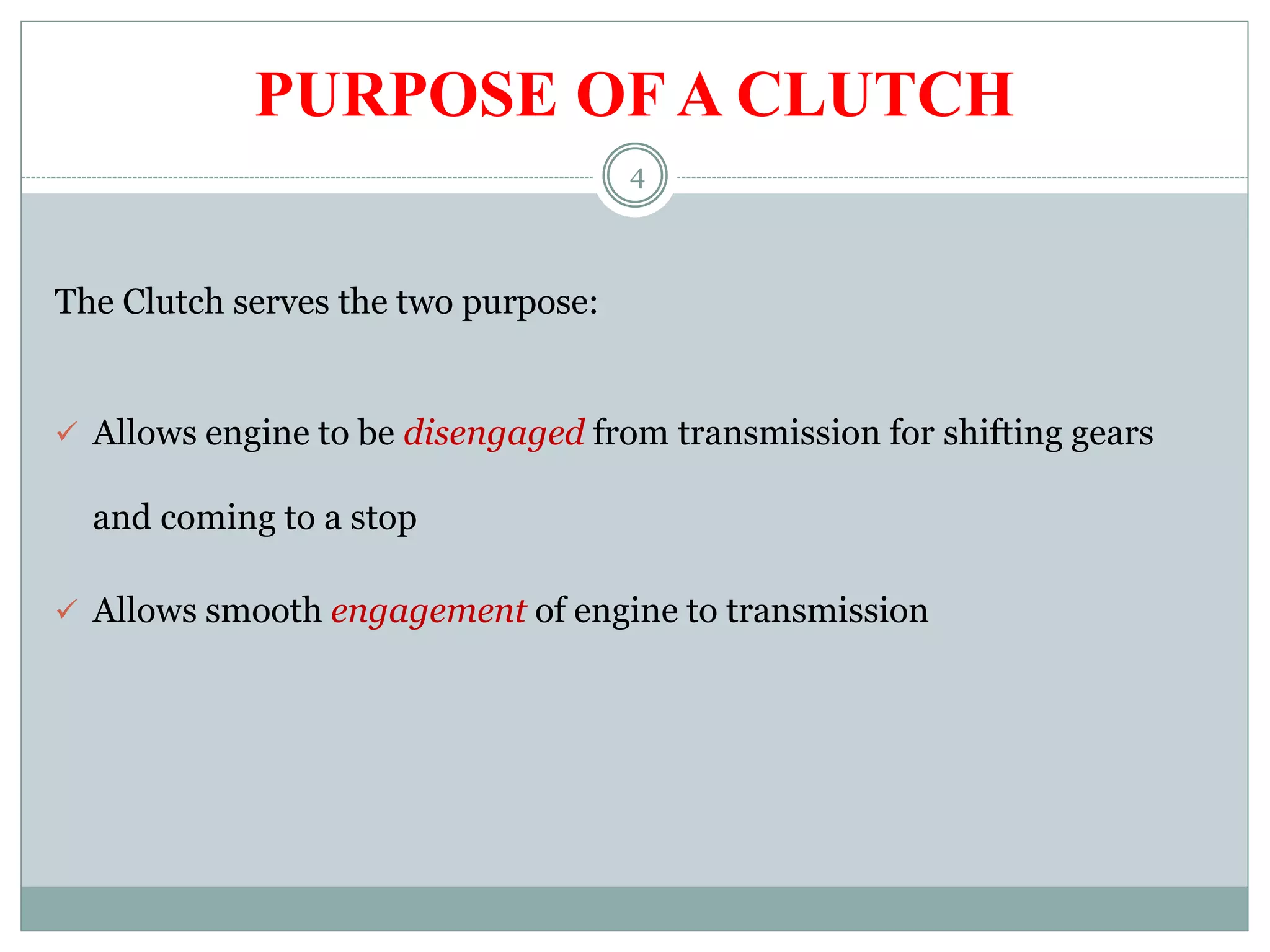
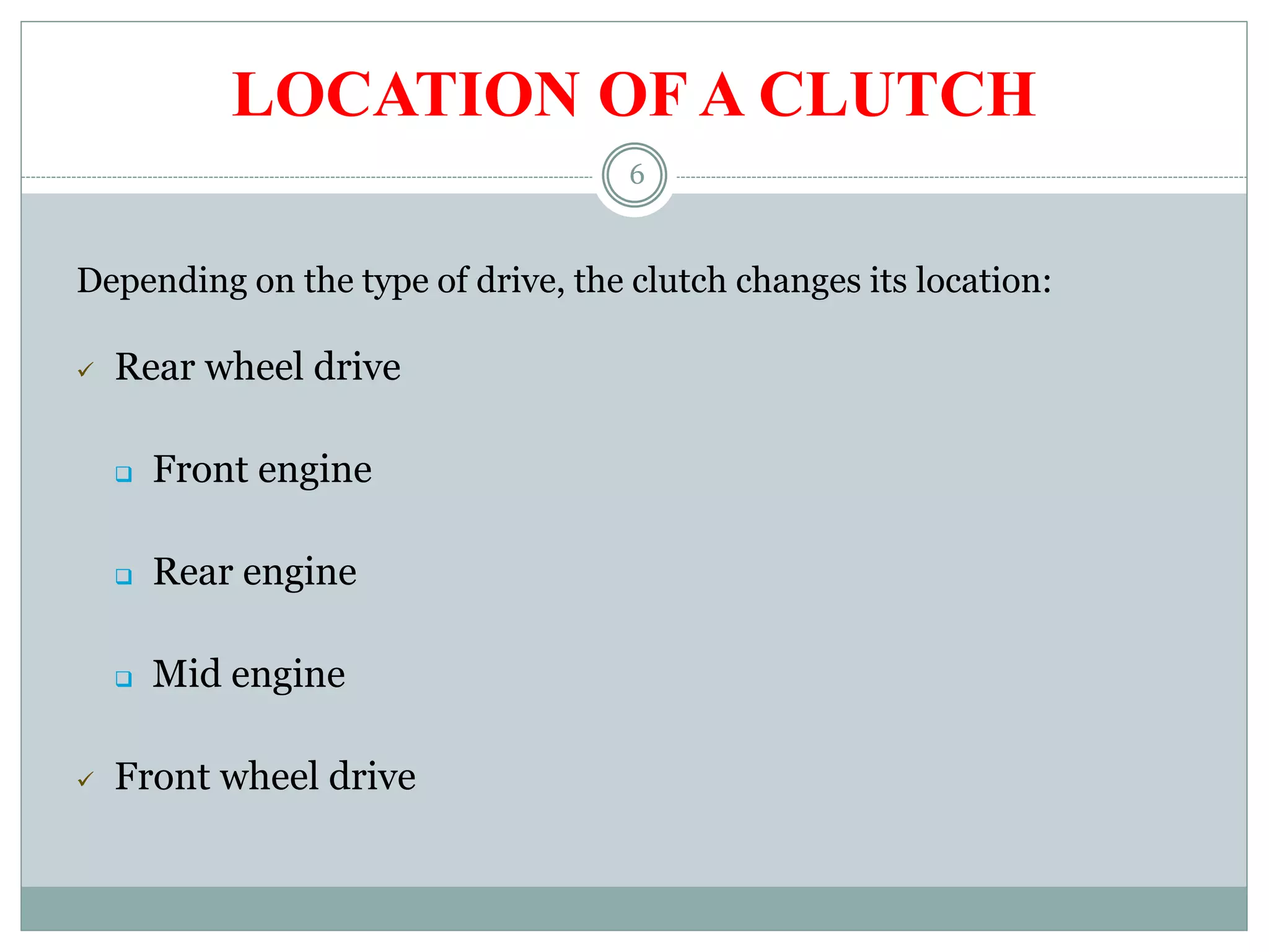
Clutches allow gear shifting and smooth engine engagement. Their location varies by drive type.
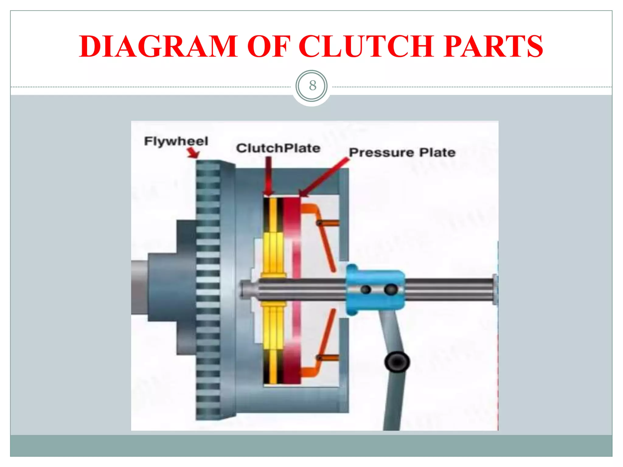
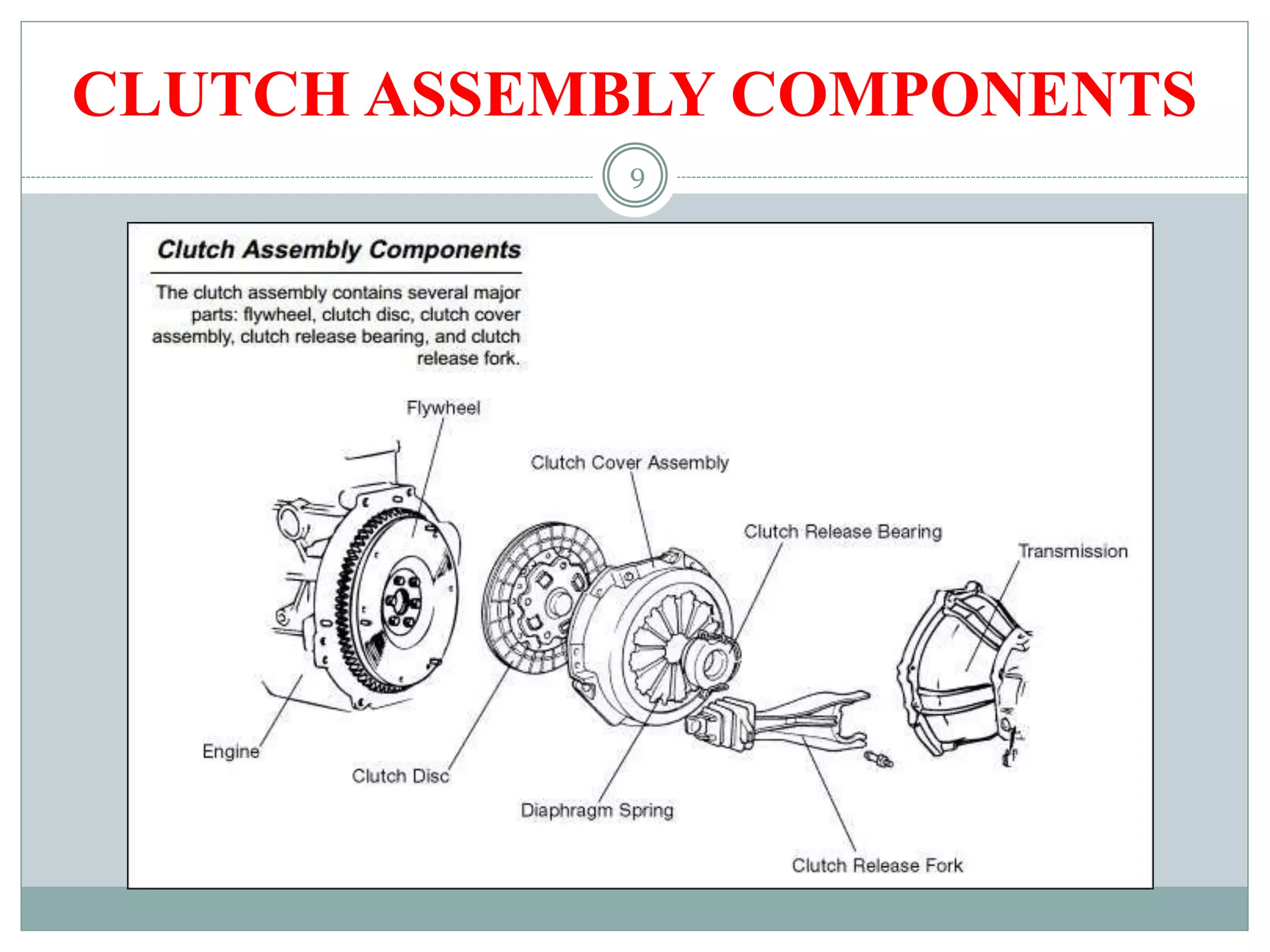
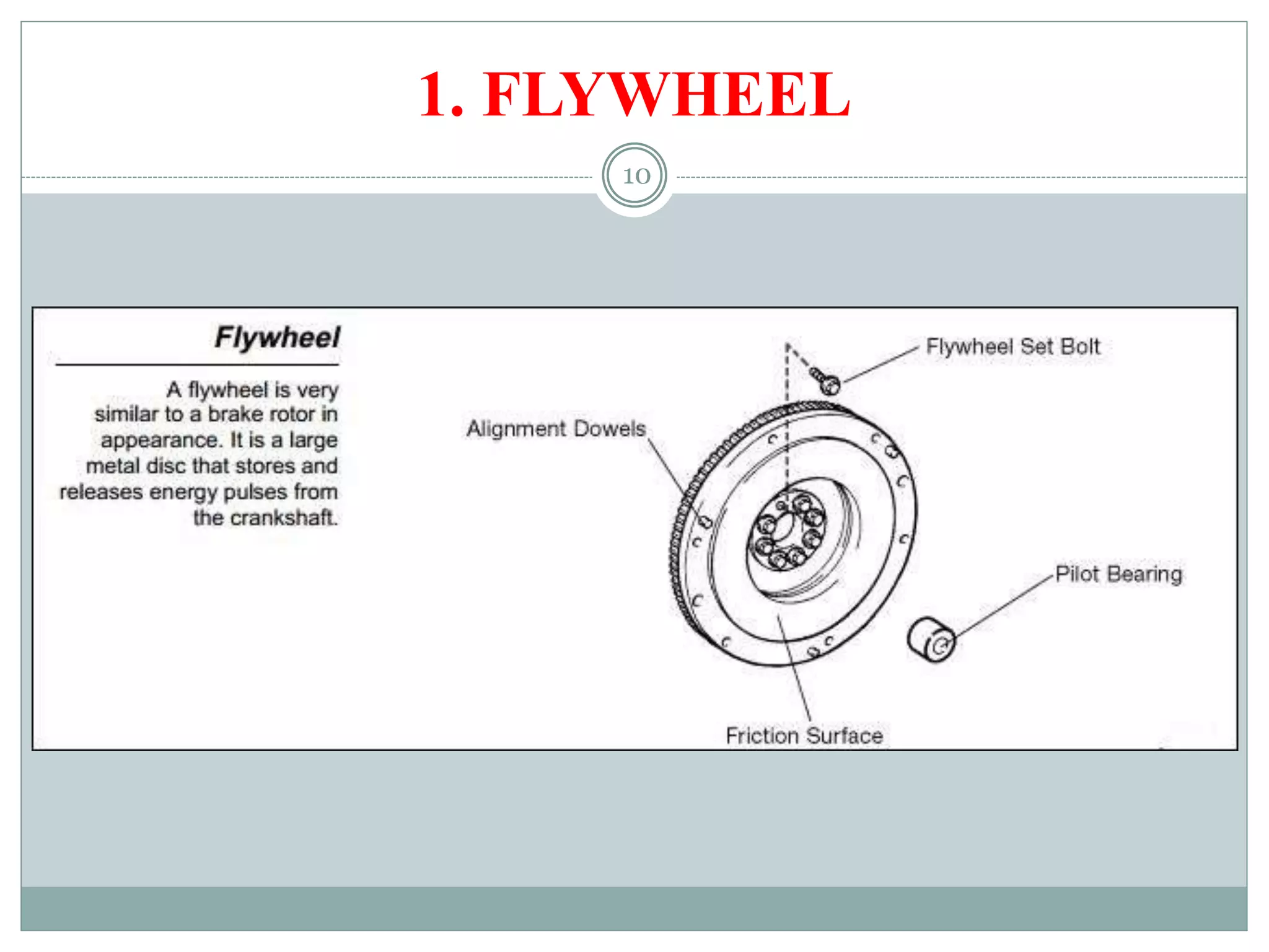
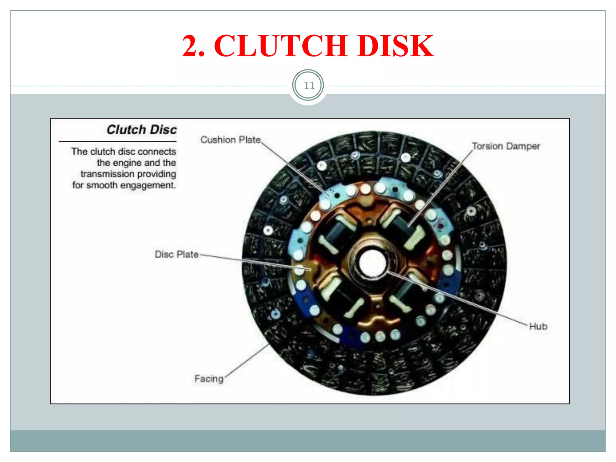
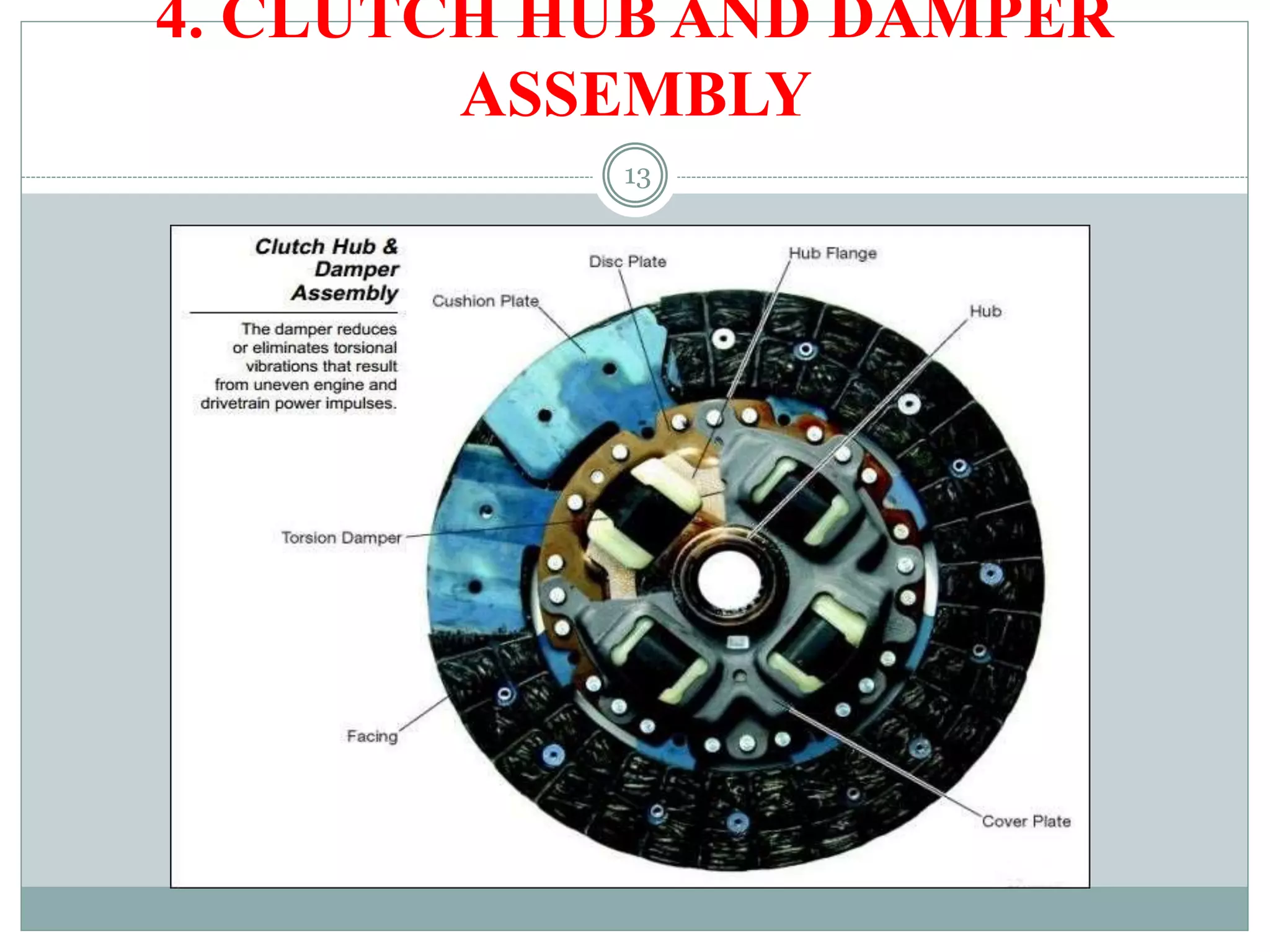
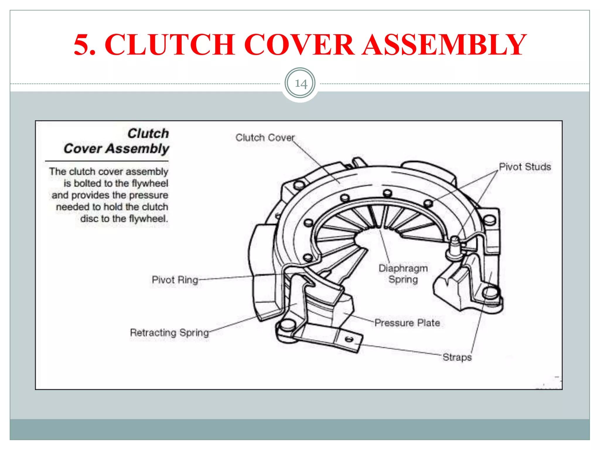
Detailed parts of a clutch assembly including flywheel, clutch disk, and cover components.
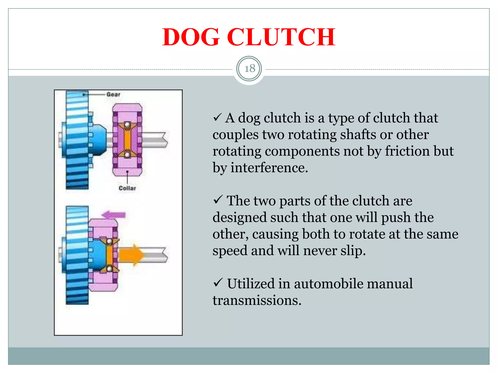
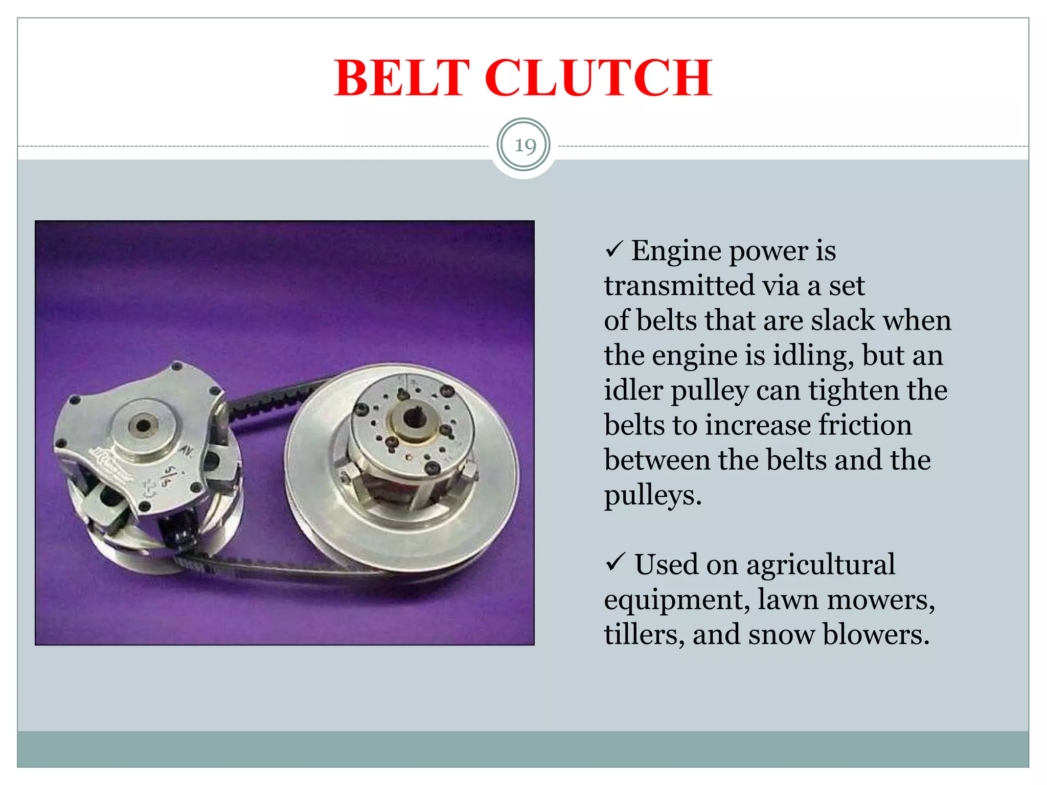
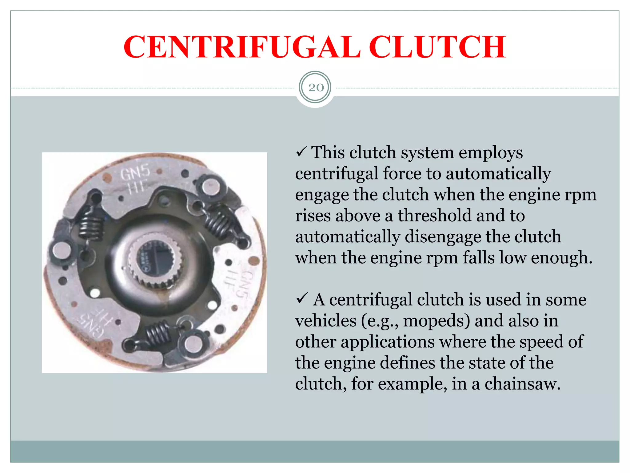
Explains three clutch types: Dog Clutch (manual transmission), Belt Clutch (power transmission), and Centrifugal Clutch (rpm responsive).
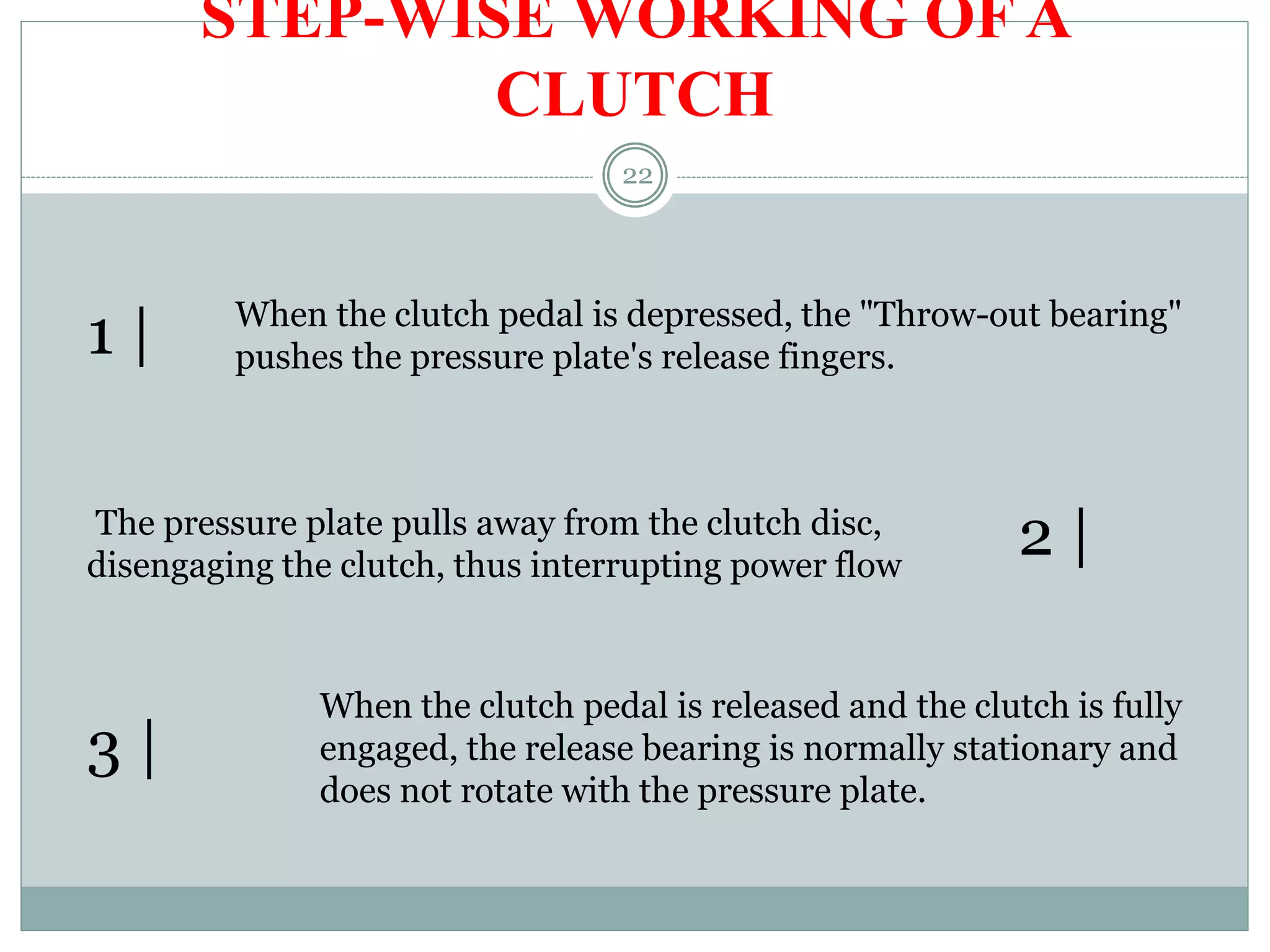
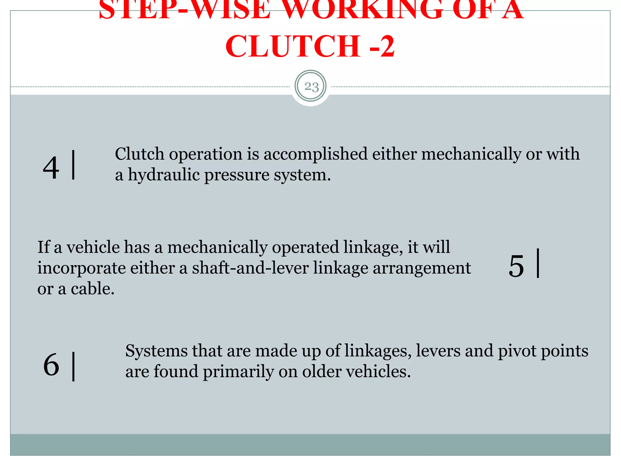
Step-by-step process of clutch operation during gear shifting, including mechanical and hydraulic systems.
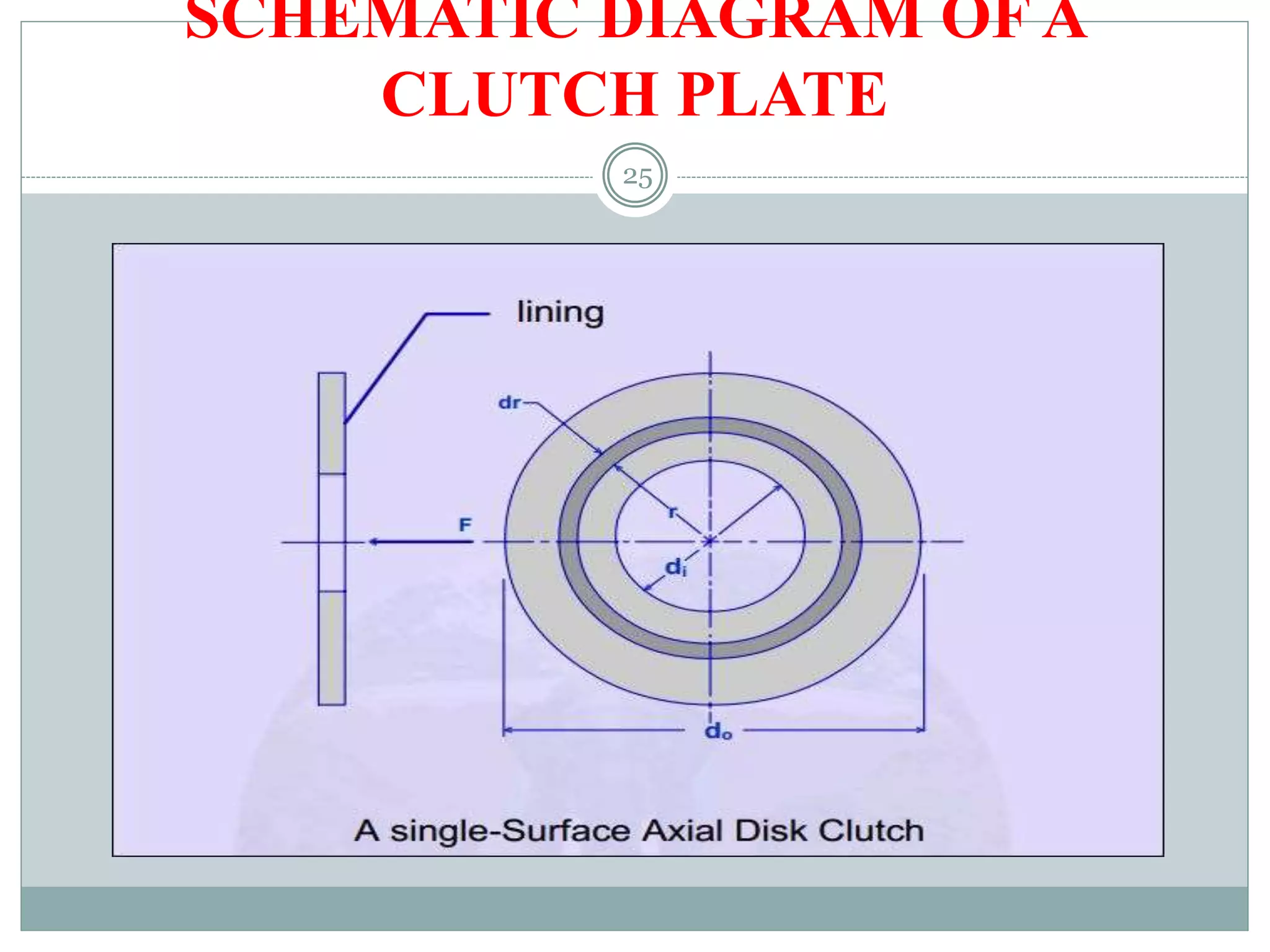
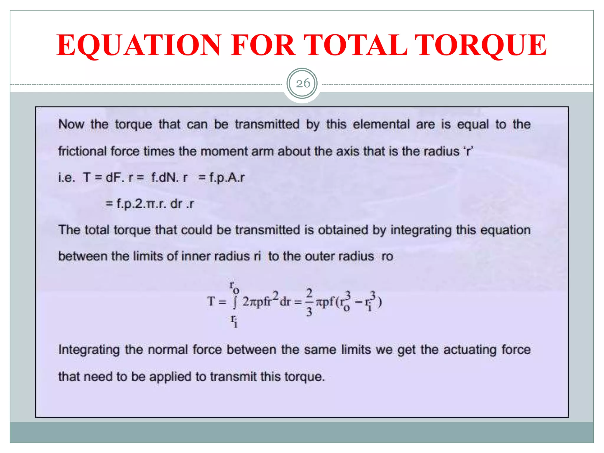
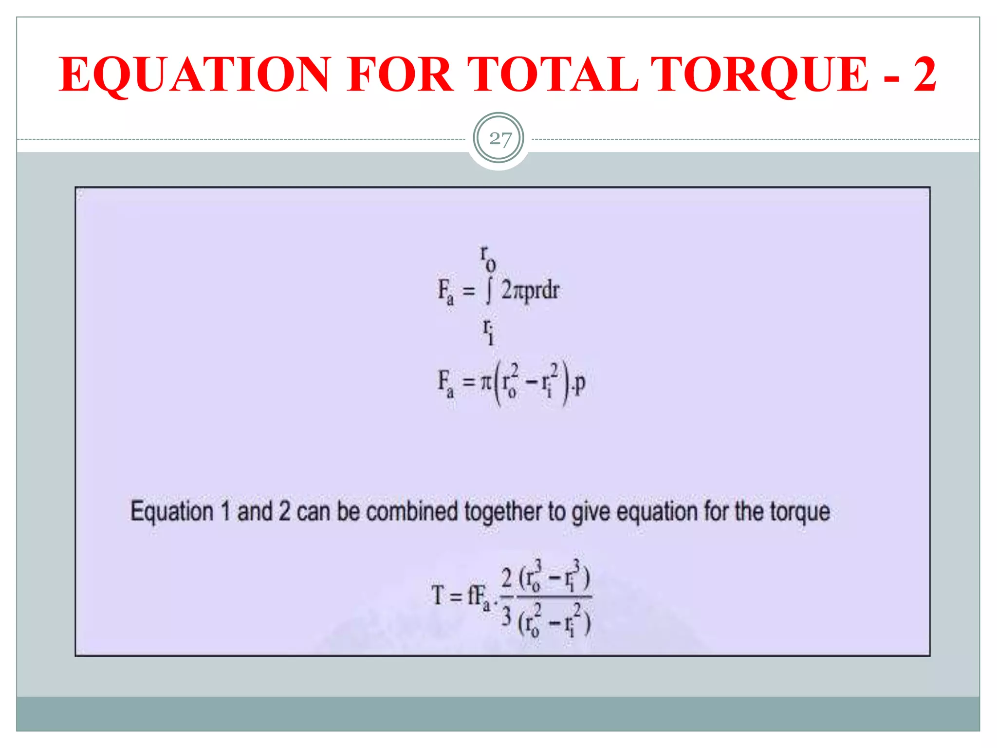
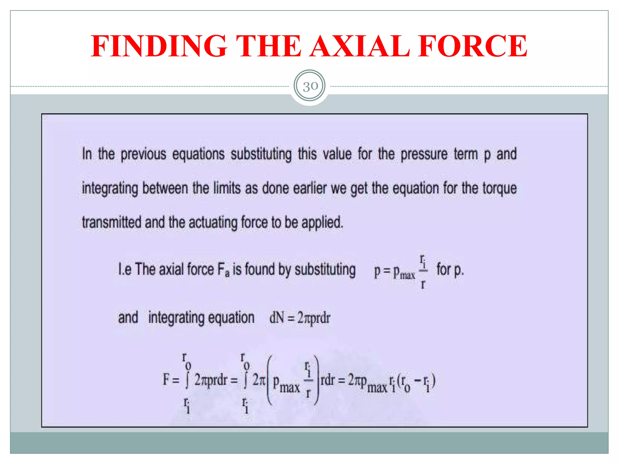
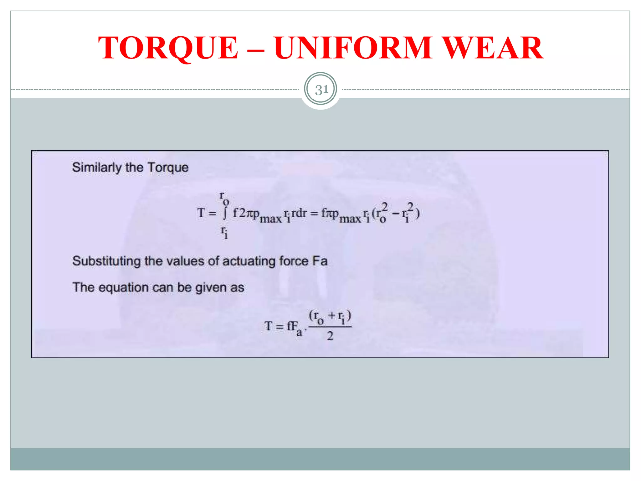
Schematic diagrams and equations for calculating total torque and axial force in clutches.
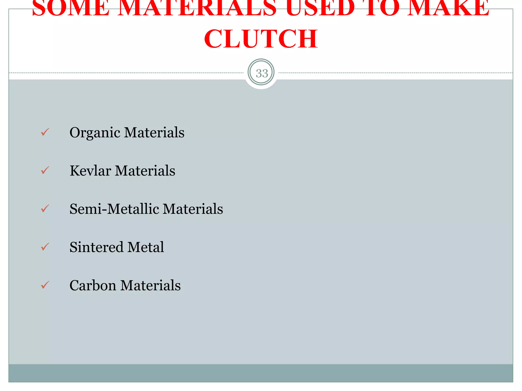
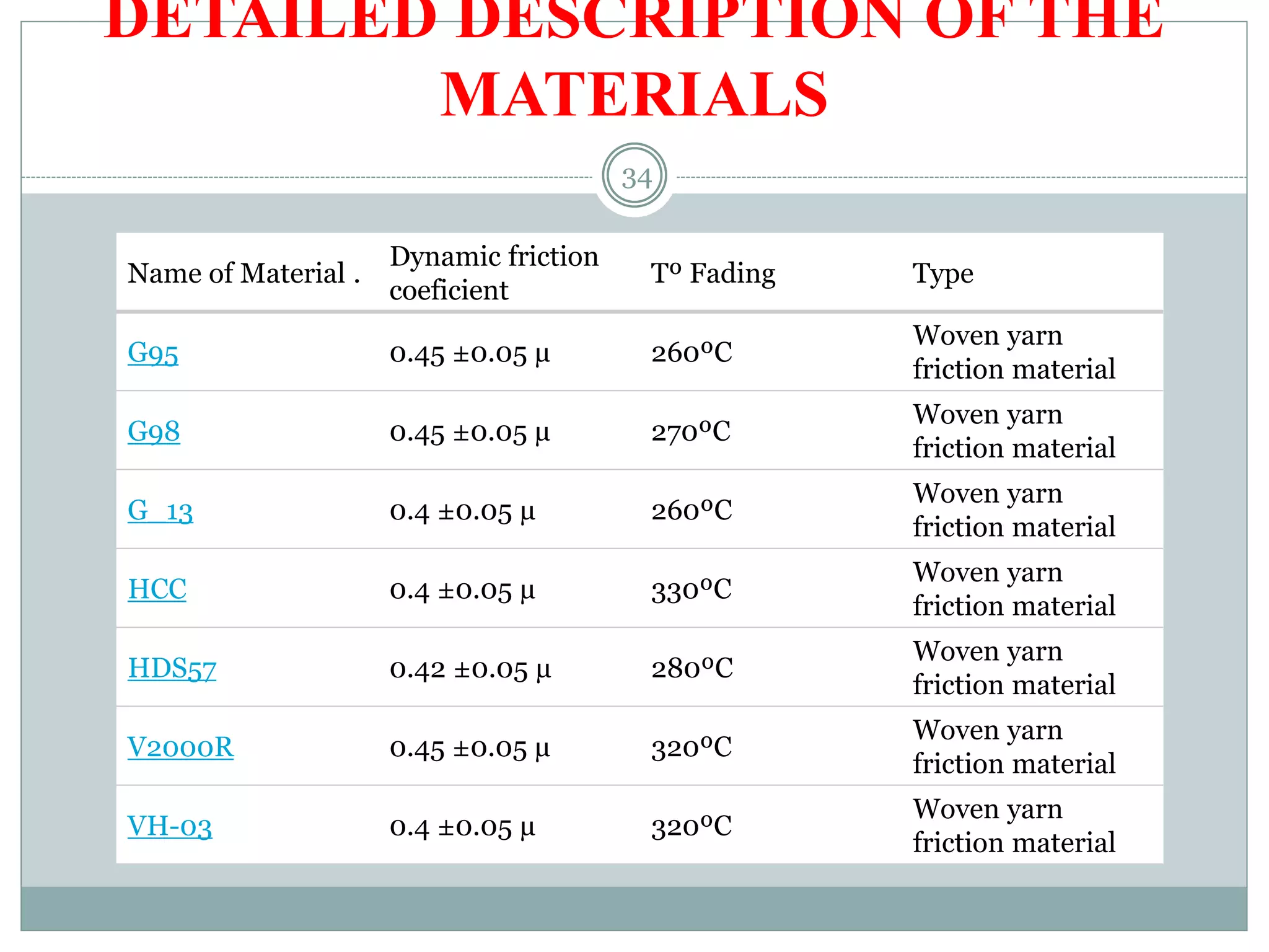
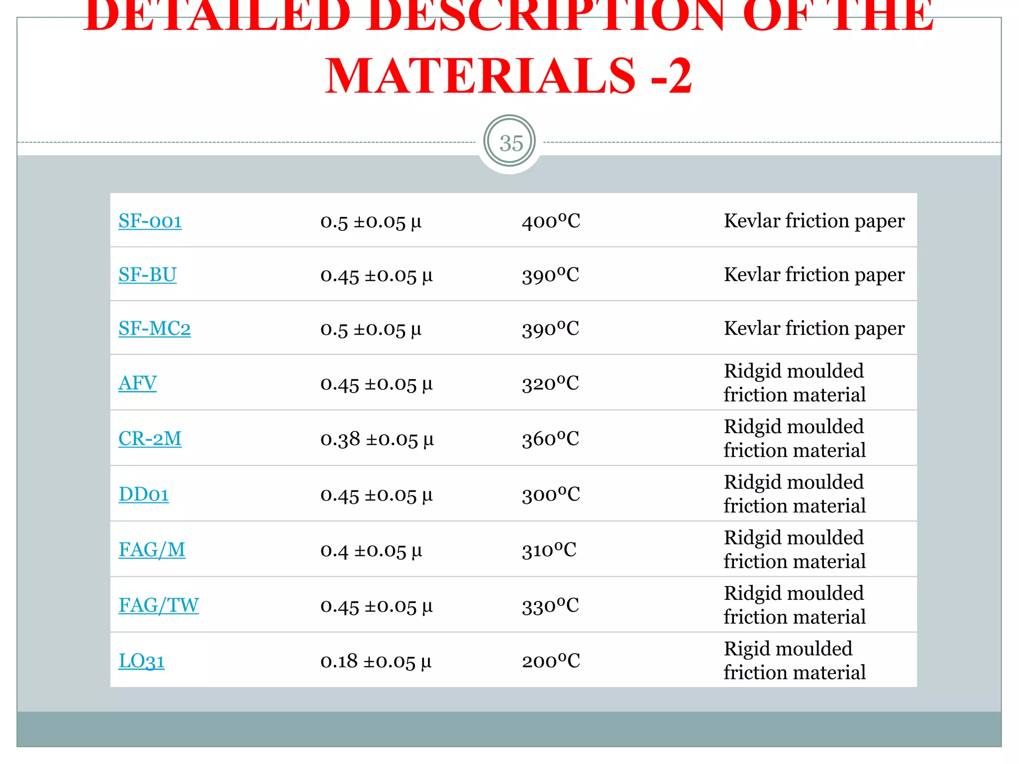
Different materials used for clutches, their properties, and dynamic friction coefficients.
Closing remarks and thanks for attending the presentation.