- Two-stroke engines complete the combustion cycle in two strokes of the piston rather than four strokes, as in four-stroke engines. They rely on crankcase compression or a blower to induct fresh air and remove exhaust gases, rather than separate intake and exhaust strokes.
- There are different types of two-stroke engines based on the scavenging method (crankcase or separately scavenged), scavenging process (cross flow, loop, uni-flow), and port timing (symmetrical or unsymmetrical).
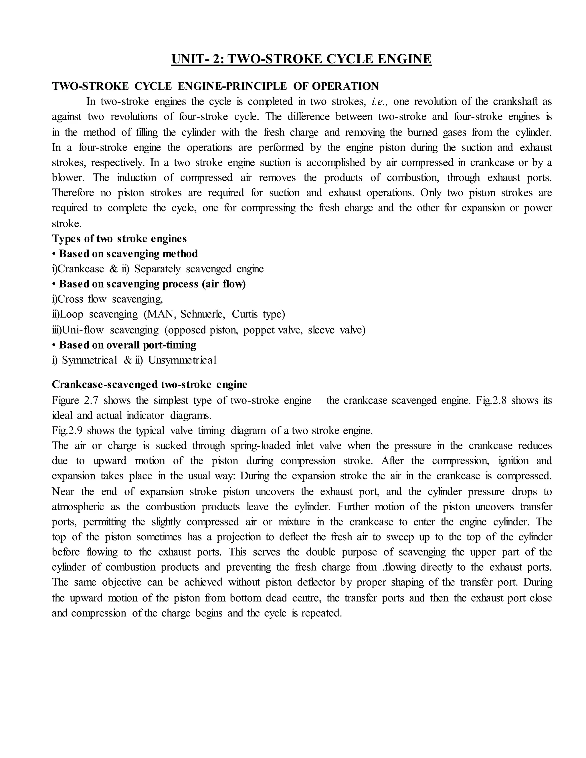
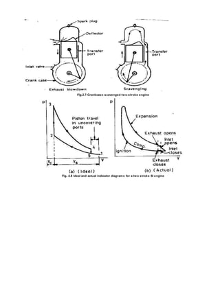
- In a crankcase-scavenged engine, the piston helps induct fresh air into the crankcase and transfers it into the cylinder, where it scavenges out exhaust gases

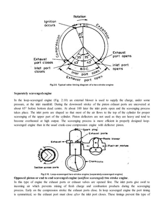
![In case of two-stroke engine the exhaust port is opened near the end of the expansion stroke. With piston-
controlled exhaust and inlet port arrangement the lower part of the piston stroke is always wasted so as far
as the useful power output is concerned; about 15% to 40% of the expansion stroke is ineffective. The actual
percentage varies with different designs. This early opening of the exhaust ports during the last part of the
expansion stroke is necessary to permit blow down of the exhaust gases and, also to reduce the cylinder
pressure so that when the inlet port opens at the end of the blow down process, fresh charge can enter the
cylinder. The fresh charge, which comes from the crankcase for scavenging pump, enters the cylinder at a
pressure slightly higher than the atmospheric pressure. Some of the fresh charge is lost due to short-
circuiting. For petrol engine this means a loss of fuel and high unburnt hydrocarbons in the exhaust. By
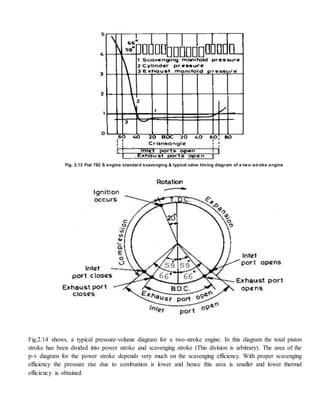
comparing the valve timing of two stroke and four-stroke engines, (Fig. 2.12), it is clear that the time
available for scavenging and charging of the cylinder of a two stroke engine is almost one-third that
available for the .four-stroke engine. For a crankcase-scavenged engine the inlet port closes before the
exhaust port whilst for a supercharged engine the inlet port closes after the exhaust port [Fig. 2.12 (b)]. Such
timing allows more time for filling the cylinder.
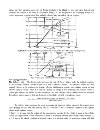
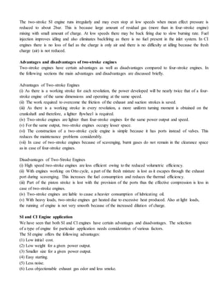
Scavenging process
At the end of the expansion stroke, the combustion chambers of a two-stroke engine is left full of
products of combustion. This is because, unlike four-stroke engines, there is no exhaust stroke available to
clear the cylinder of burnt gases. The process of clearing the cylinder of burned gases and filling it with](https://image.slidesharecdn.com/twostrokecycleengine-150227043620-conversion-gate01/85/Two-stroke-cycle-engine-5-320.jpg)


![Electronic fuel injection system [EFI]](https://cdn.slidesharecdn.com/ss_thumbnails/efibilkulfinal-171227111232-thumbnail.jpg?width=640&height=640&fit=bounds)


