This document provides an overview of key concepts in automobile engineering, including:
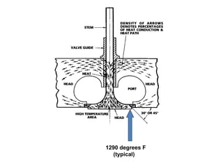
1) It describes how energy from fuel is converted to heat through combustion in the engine, and how engine power or horsepower depends on factors like engine size, speed, and load.
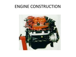
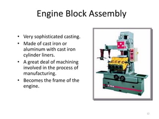
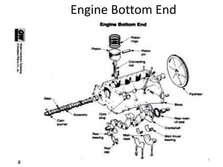
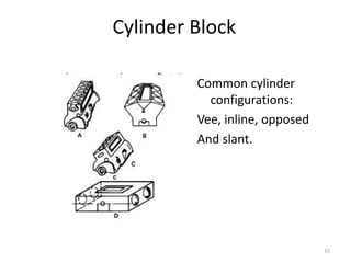
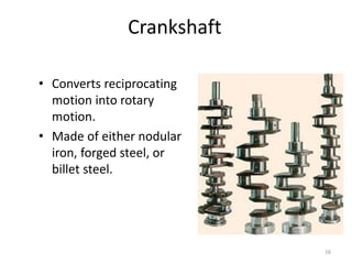
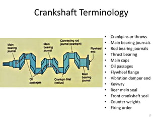
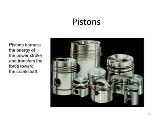
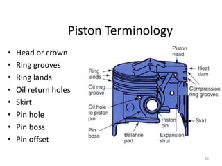
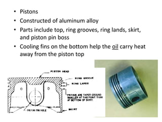
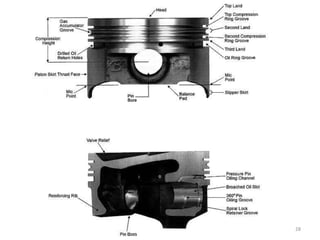
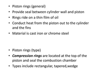
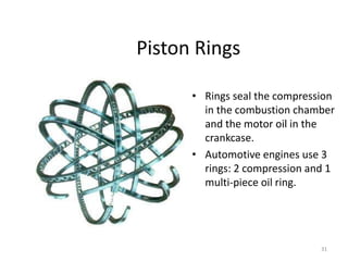
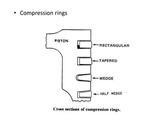
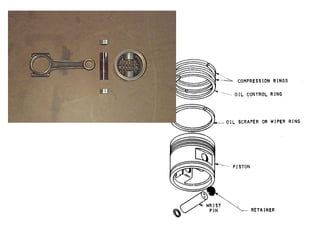
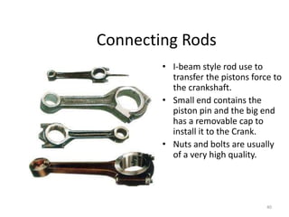
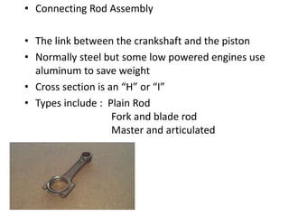
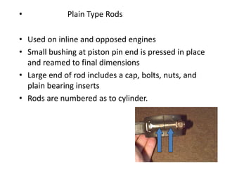
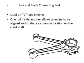
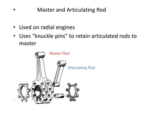
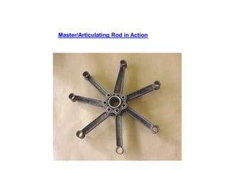
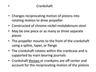
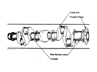
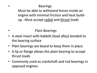
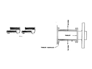
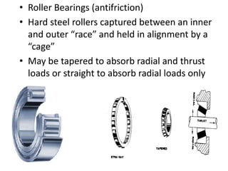
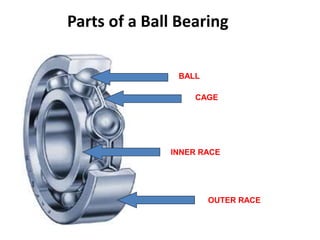
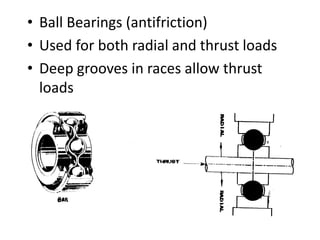
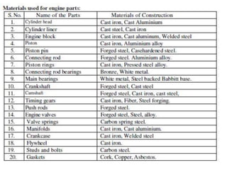
2) Key components of an engine like the crankshaft, connecting rods, pistons, rings, and bearings are explained. The crankshaft converts reciprocating motion to rotation, and components work together to harness energy from combustion.
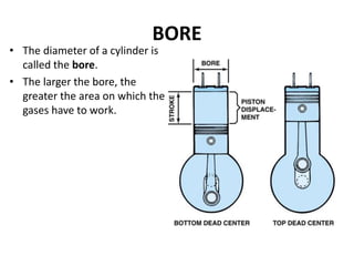
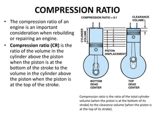
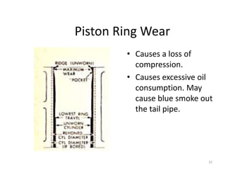
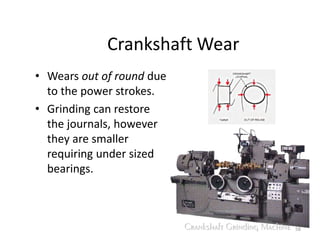
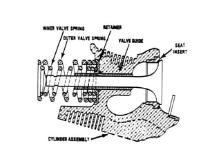
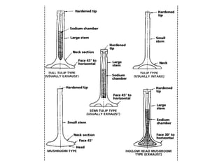
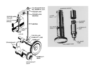
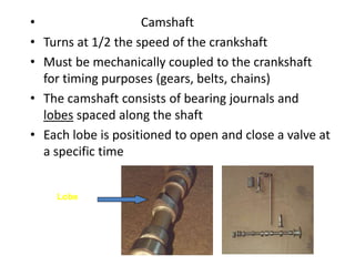
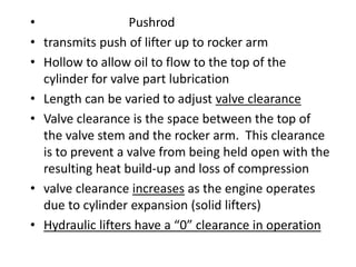
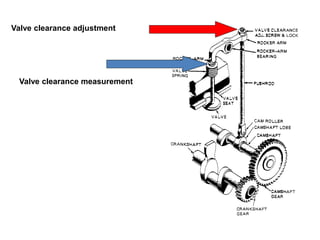
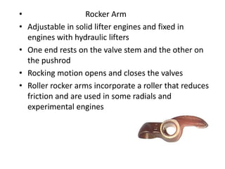
3) Additional concepts covered include torque, bore and stroke, displacement, compression ratio, cylinder wear patterns, and the functions of valves, cams, pushrods, lifters, and rock