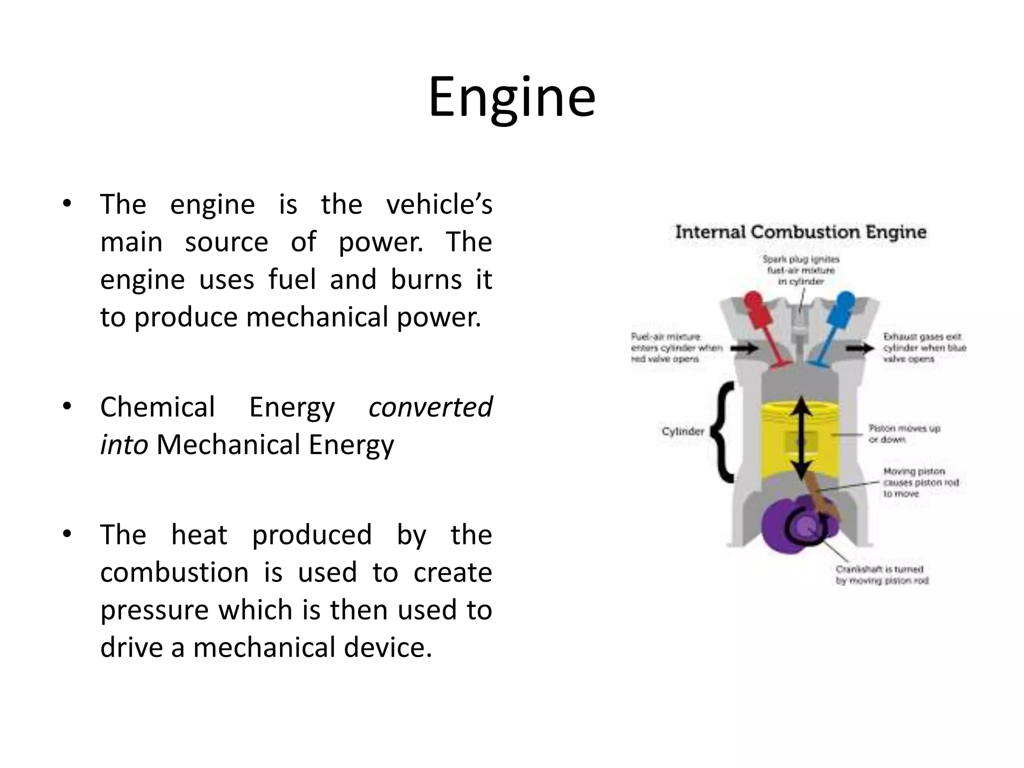
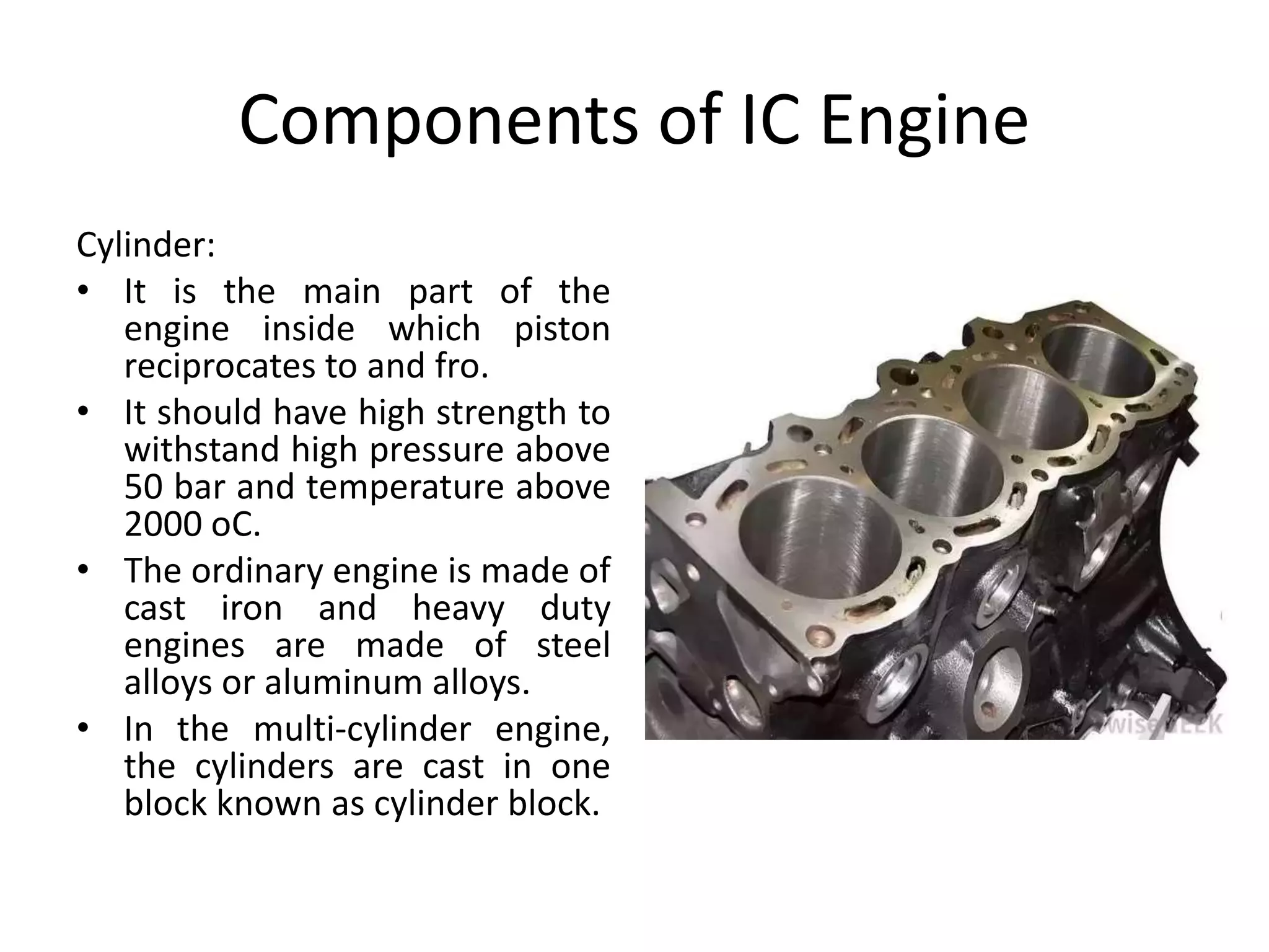
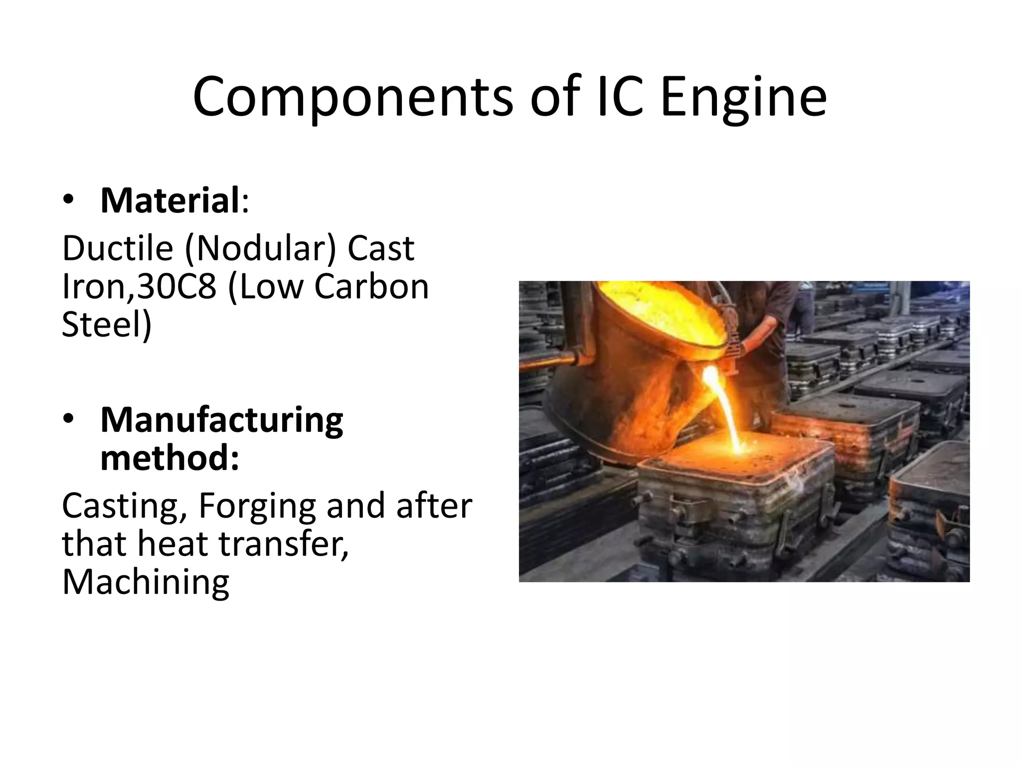
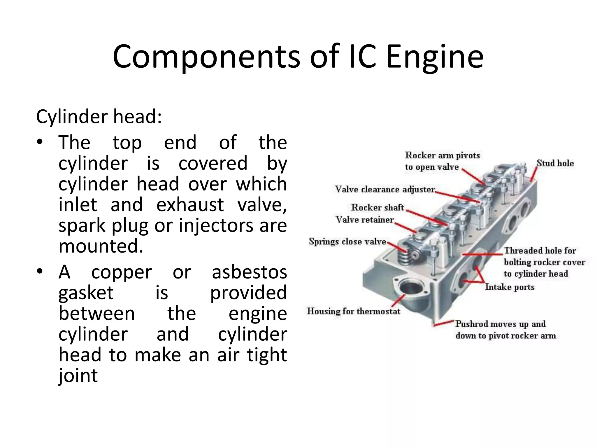
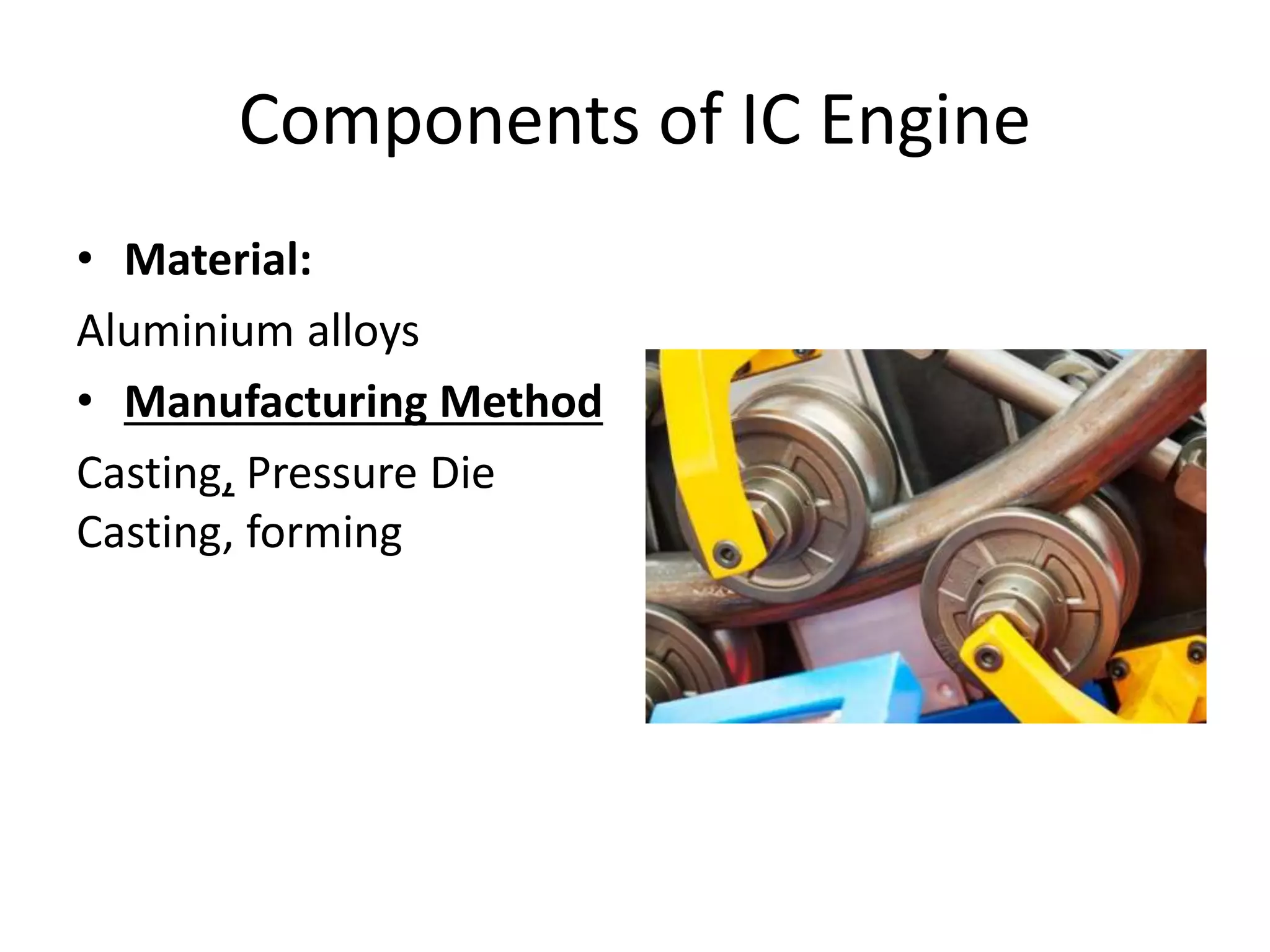
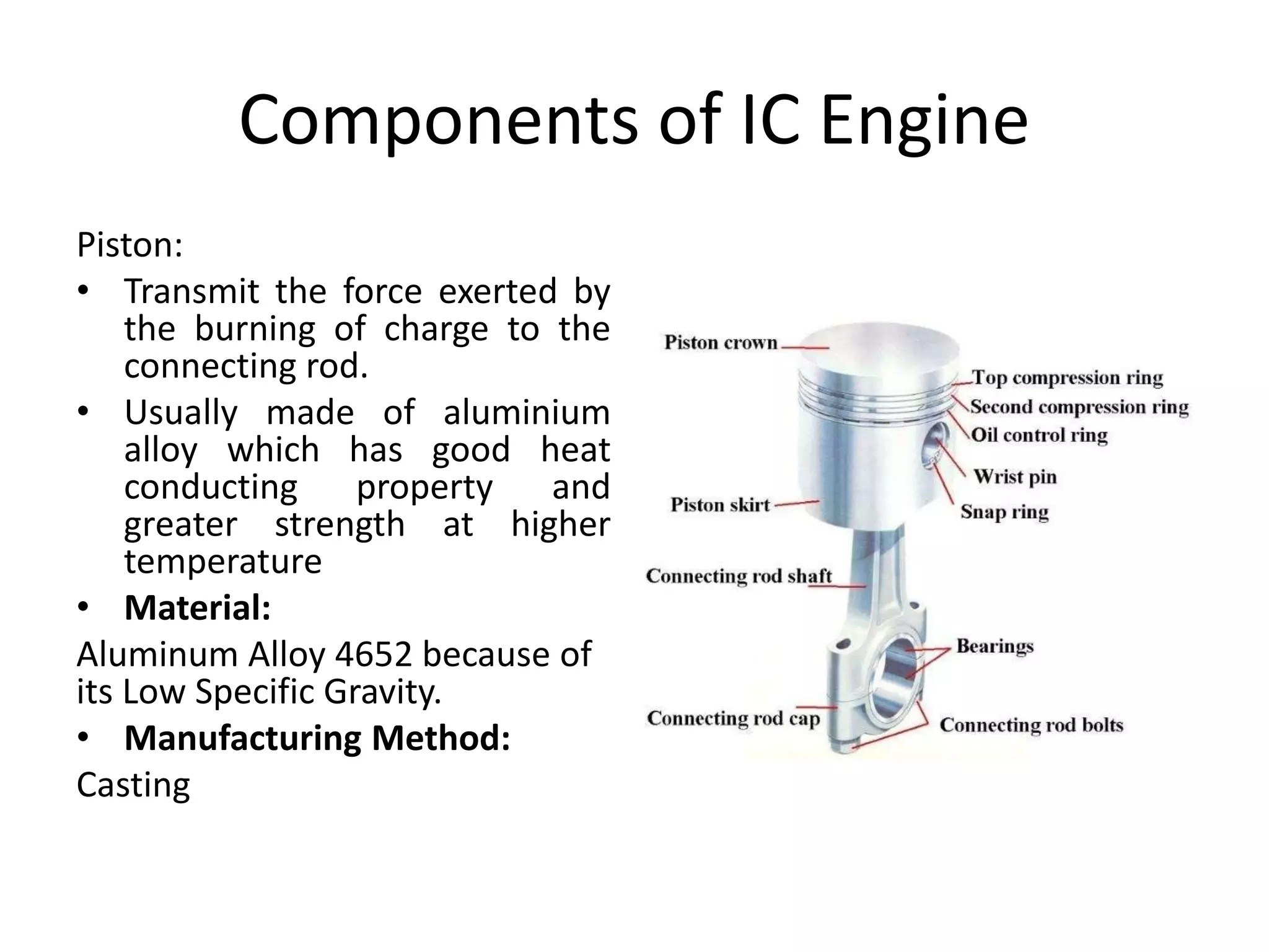
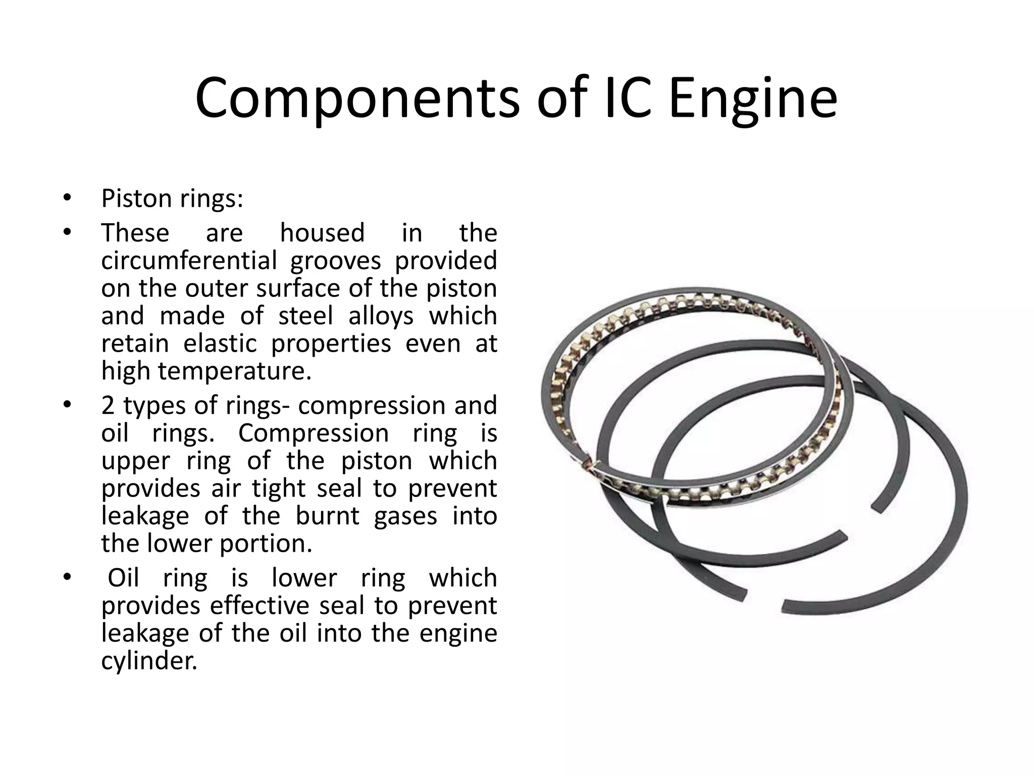
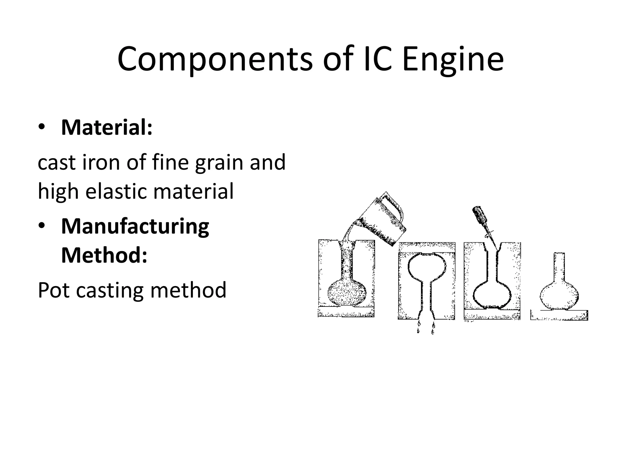
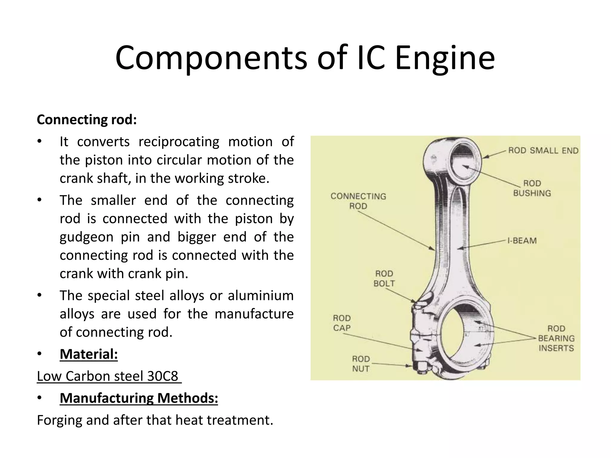
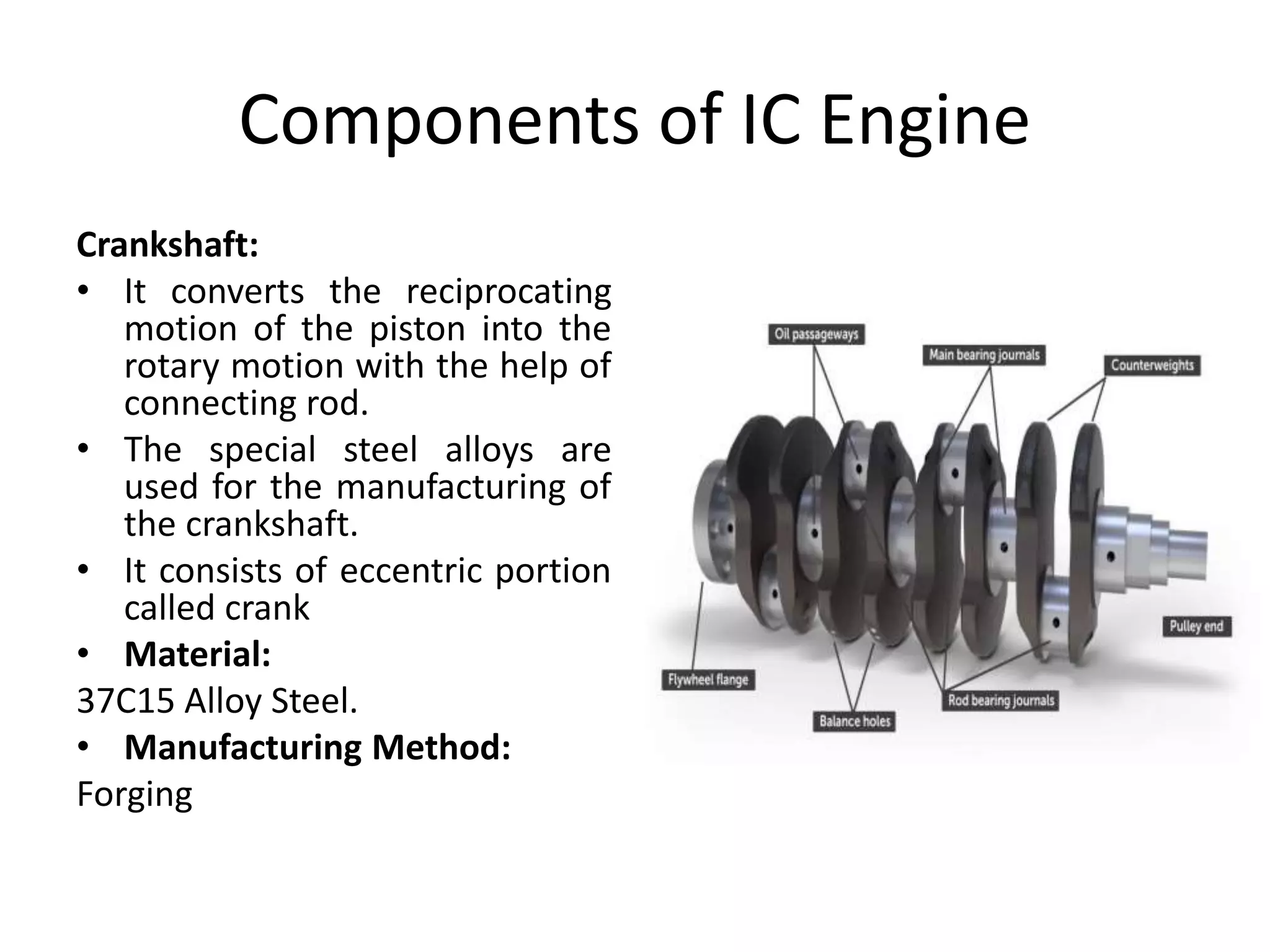
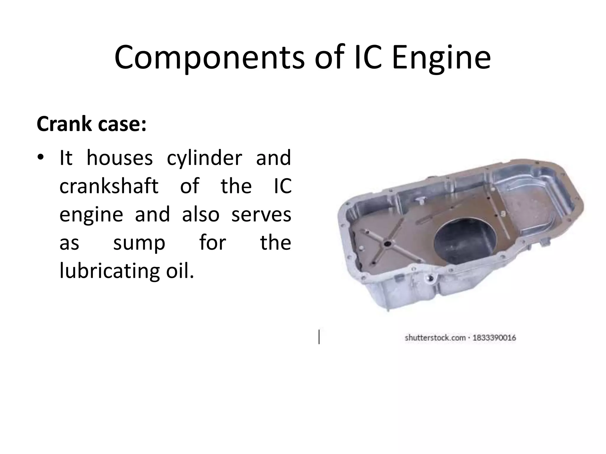
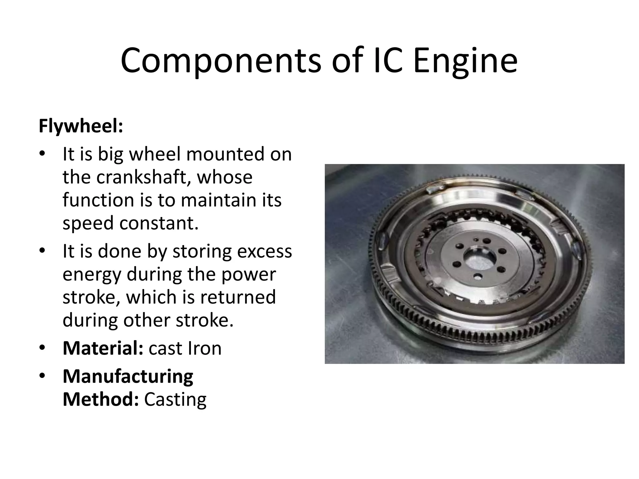
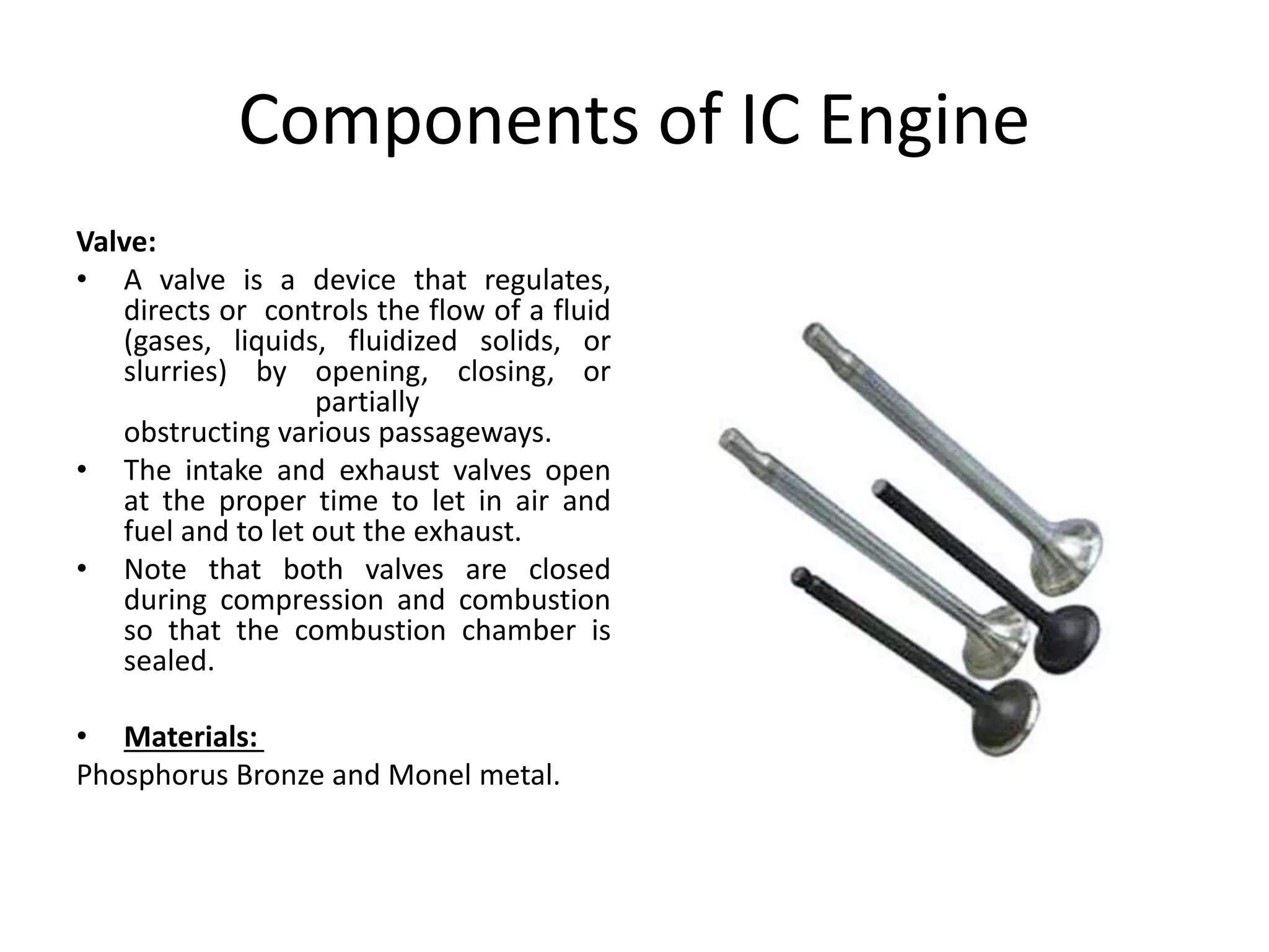
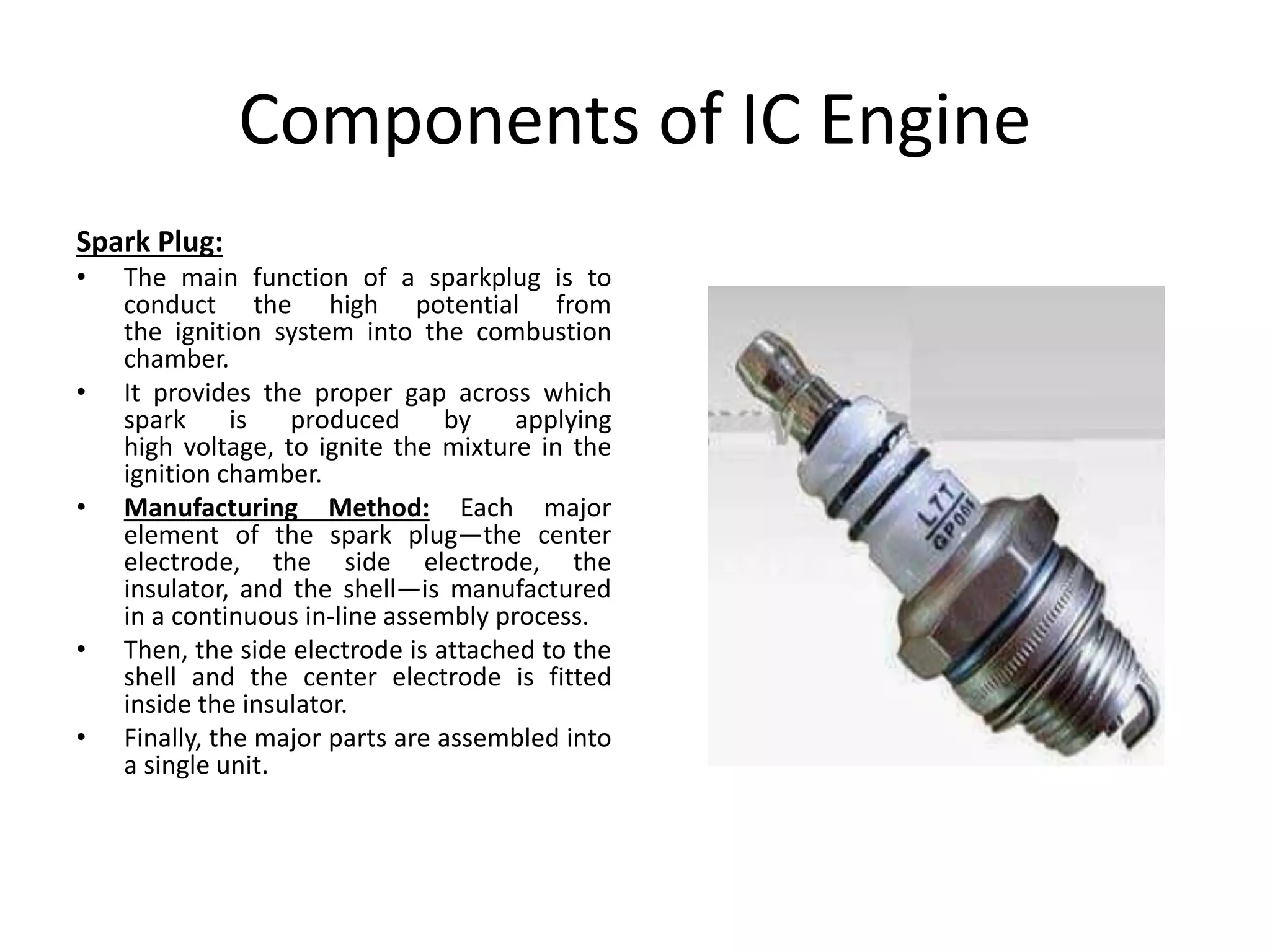
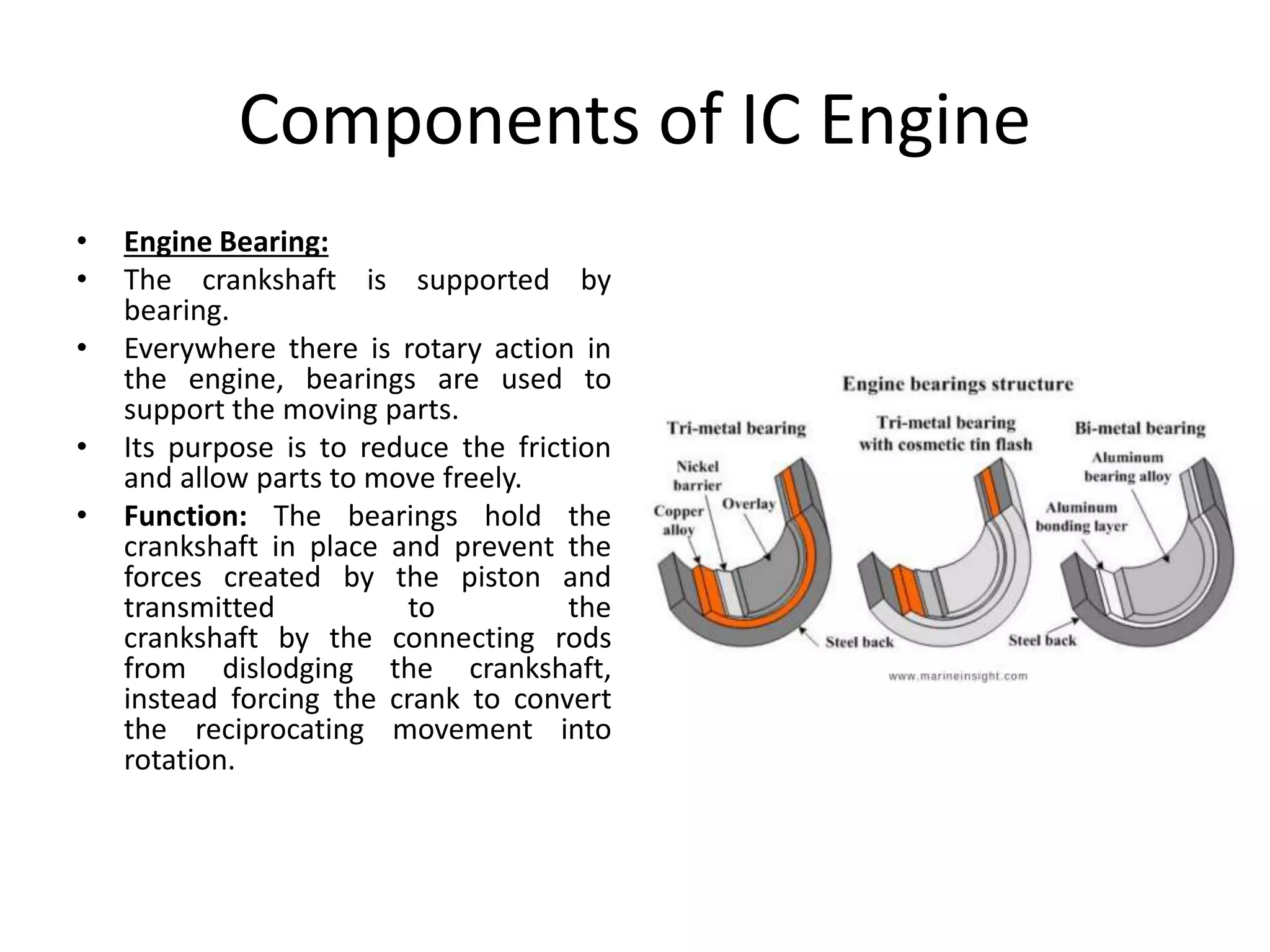
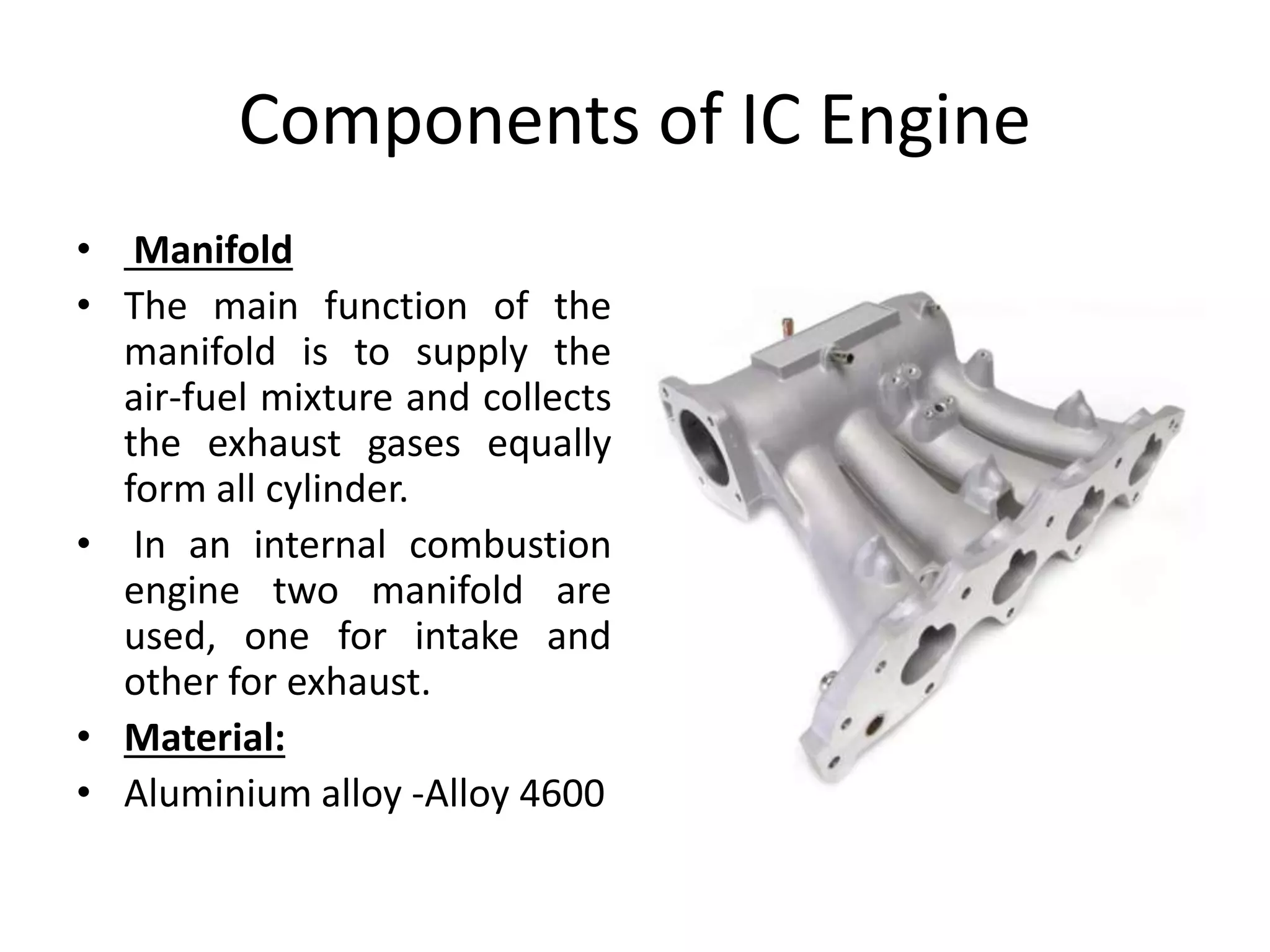
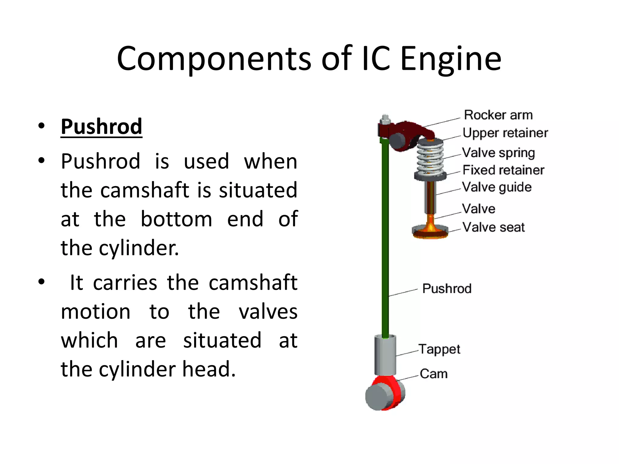
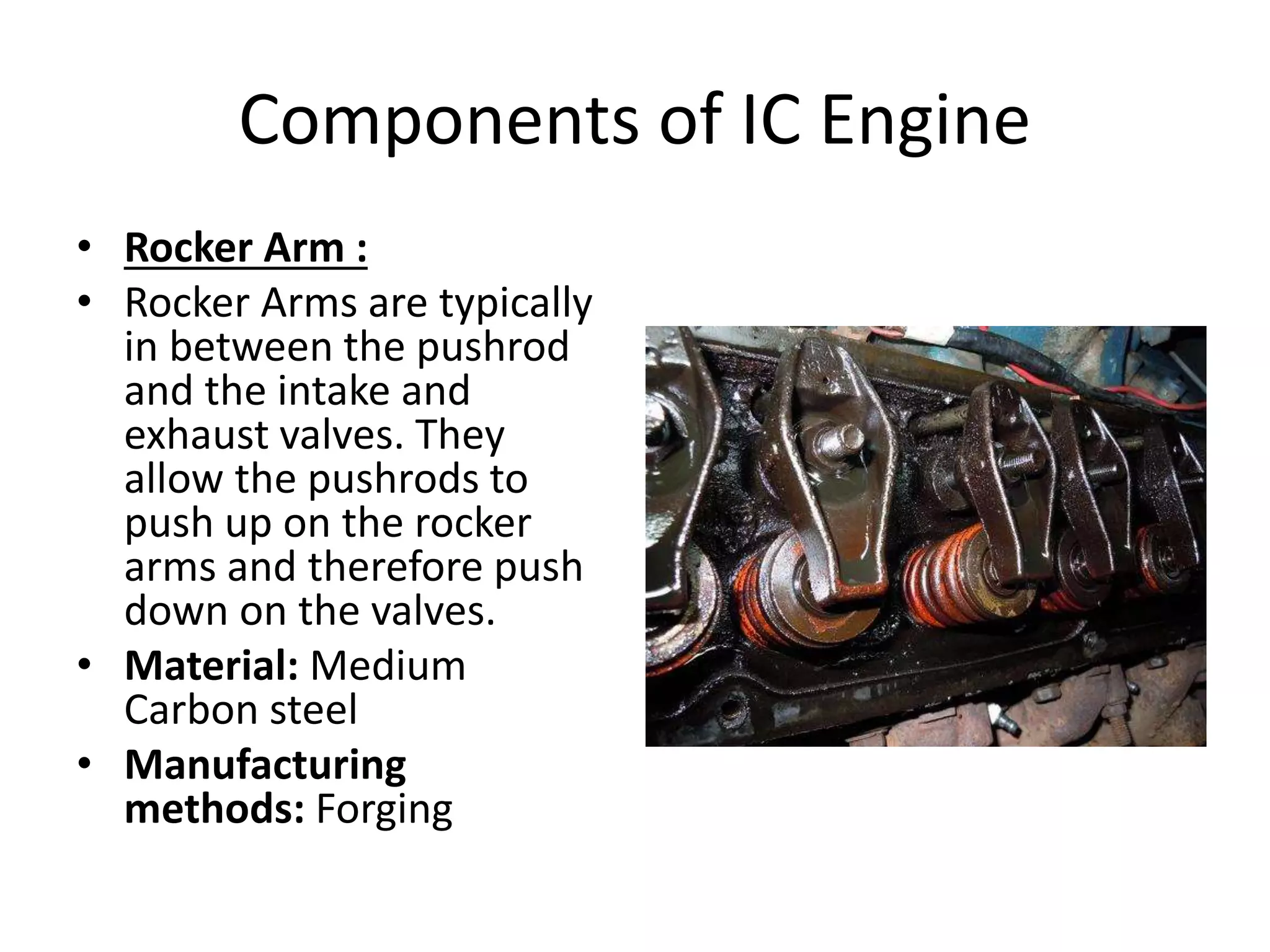
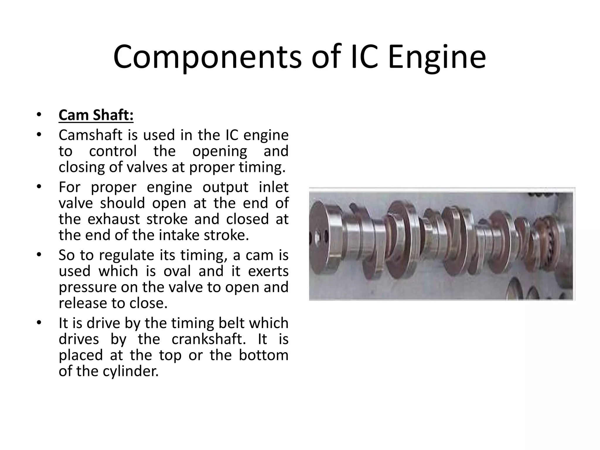
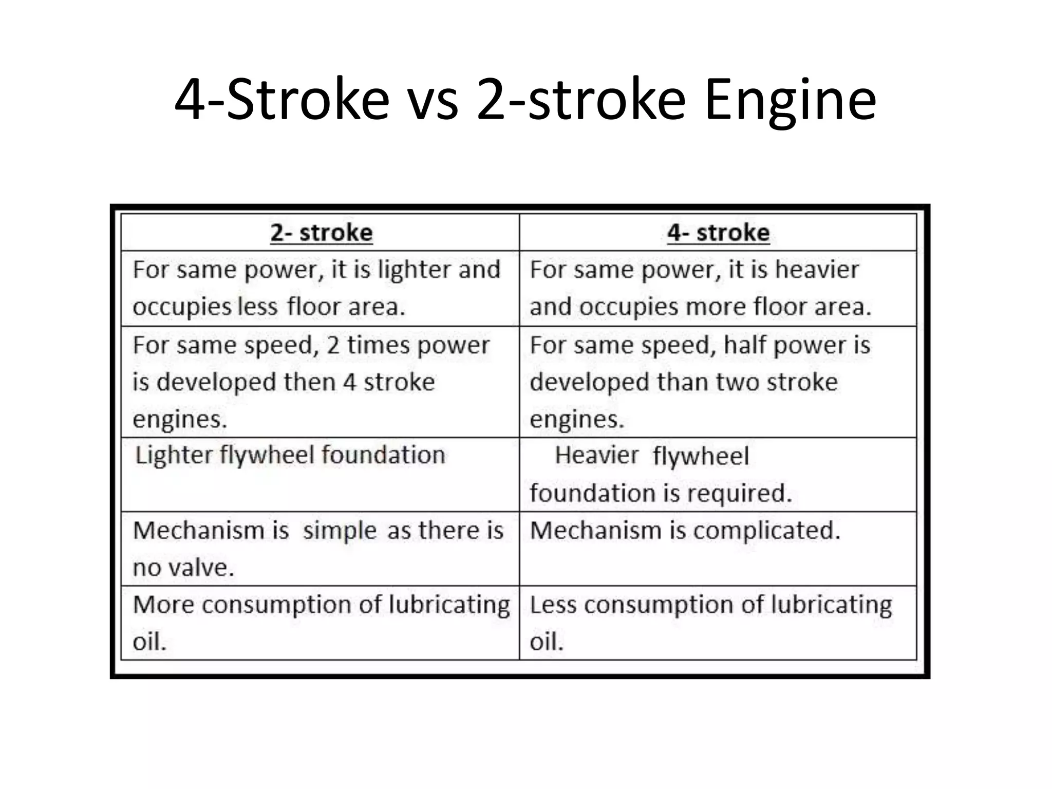
The document provides an overview of fundamentals of engine technologies. It discusses the historical development of internal combustion engines and classifications such as 2-stroke and 4-stroke engines. It describes the key components of an internal combustion engine such as the cylinder, cylinder head, piston, connecting rod, crankshaft, crankcase, flywheel, valves, and spark plug. It explains the materials and manufacturing processes used for various engine components.
The document provides an introduction to the basic systems of an internal combustion (IC) engine, including:
- Heat engines and the difference between internal and external combustion engines
- IC engine terminology and the four-stroke operating cycle
- Engine construction components like the cylinder block, piston, connecting rod, cylinder head, and flywheel
- Ignition, fuel, lubrication, and cooling systems
- Types of IC engines classified by design, fuel used, number of strokes, ignition method, cylinders, and cooling method
The summary captures the key topics and essential information covered in the document regarding the fundamental components and systems that make up IC engines.
1) The document discusses the assembly, disassembly and maintenance of internal combustion (IC) engines. It covers the main components of IC engines like the cylinder block, cylinder head, piston, connecting rod, crankshaft and camshaft.
2) IC engines are classified based on their cycle of operation, thermodynamic cycle, type of fuel used, ignition method, cooling system and valve location. The working of four-stroke petrol engines, four-stroke diesel engines, and two-stroke petrol and diesel engines are explained.
3) The key components, working cycles and strokes of different engine types are described in detail.
Internal Combustion E Presentation PPt.pdfZainSalleh1
The document discusses internal combustion engines. It defines heat engines and classifies them as internal combustion engines and external combustion engines. It then further classifies internal combustion engines based on their cycle of operation, thermodynamic cycle, type of fuel used, ignition method, cooling system, and valve location. It describes the key components of internal combustion engines including the cylinder block, cylinder head, pistons, piston rings, connecting rod, crankshaft, and camshaft. It also provides details on the construction and working of four-stroke petrol engines and four-stroke diesel engines.
IC engines(2 stroke/4 stroke),Engine terminology and major components,Power transmission drives(belt ,gear ,rope ,chain),Clutch, Brake,CRDI,MPFI& HYBRID
The document provides definitions and descriptions of key components and processes in internal combustion engines. It discusses the four main components - block, cylinder head, crankshaft and pistons. It also summarizes the four strokes of the internal combustion engine cycle: 1) intake/suction stroke, 2) compression stroke, 3) combustion, 4) power/exhaust stroke. The compression and combustion processes are described in detail.
1. The internal combustion engine derives power from fuel burned within the engine cylinder. The key components include the cylinder, cylinder head, piston, connecting rod, crankshaft, camshaft, valves, manifolds, and flywheel.
2. The cylinder provides the combustion chamber where the air-fuel mixture is compressed and ignited. The piston is connected to the crankshaft via the connecting rod to convert the linear motion of the piston into rotational motion.
3. The camshaft opens and closes the valves using lobes to allow air-fuel intake and exhaust, and is driven by the crankshaft via gears or a chain. Together these components work to convert the energy from combustion
The internal combustion engine has a combustion chamber where fuel is burned. This creates high temperature and pressure gases that are used to do work by expanding. The main components of an internal combustion engine include the cylinder head, cylinder block, pistons, connecting rod, crankshaft, camshaft, valves, flywheel, and systems for fuel, ignition, cooling, lubrication, and filtering air. The engine uses precise timing of its components to intake, compress, combust, and exhaust the fuel-air mixture in order to efficiently convert the chemical energy of the fuel into useful mechanical work.
This document provides an overview of engine types and components presented by Vishal Singh of Raj Sons Auto Pvt. Ltd. It discusses the basic components and functions of engines, including pistons, connecting rods, crankshafts, and various engine types classified by combustion method, number of strokes, cylinder arrangement, and ignition method. It also summarizes lubrication basics, describing how oil is pulled from the sump through the filter and pump to lubricate engine components before draining back to the sump.
1. The document provides information about the internal combustion engine course including its objectives, classification of IC engines based on different parameters, working of 2-stroke and 4-stroke engines, engine components, performance parameters like indicated power, brake power, efficiencies.
2. It classifies IC engines based on number of strokes, thermodynamic cycle, ignition mechanism, fuel used, cooling type and motion. It also explains the working of 2-stroke and 4-stroke engines along with the thermodynamic cycles.
3. The document discusses engine components, performance evaluation parameters like indicated power, brake power, efficiencies and provides formulas to calculate them. It also compares SI and CI engines along with 2-stroke and 4-stroke
This document provides an overview of internal combustion engines. It begins with definitions of heat engines and the two main types - external combustion engines and internal combustion engines. The key differences between spark ignition engines and compression ignition engines are outlined. Four-stroke and two-stroke engine cycles are described and compared. The main components of internal combustion engines are defined. The document also includes classifications of IC engines, histories of important developments, and diagrams illustrating valve and port timing. Thermal concepts like indicated power, brake power, and efficiency are defined.
Internal combution of Engine (two stroke and four stroke)drpradeepkumar34
Unit 2 introduces IC engines and electric vehicles. For IC engines, it covers the basic components, construction, and working of two-stroke and four-stroke SI and CI engines. It discusses the differences between two-stroke and four-stroke engines, and between SI and CI engines. For electric vehicles, it discusses the components of EVs including batteries and chargers, as well as the advantages and disadvantages of EVs. It also introduces hybrid electric vehicles and their components and advantages.
difination and explaintion of 2 strike vs 4stroke enginees including defination, ragulation types of and examples explation for educations and projects
1. The document discusses different types of internal combustion (IC) engines, including their classifications, components, and operating cycles.
2. IC engines are classified based on their cycle of operation, thermodynamic cycle, type of fuel used, ignition method, cooling system, and valve location. The main components of IC engines include the cylinder block, cylinder head, pistons, connecting rods, crankshaft, and camshaft.
3. Petrol engines can operate on a four-stroke or two-stroke cycle, while diesel engines typically use a four-stroke cycle. The document explains the workings of four-stroke petrol, diesel, and two-stroke petrol engines through their intake, compression, power,
The document discusses internal combustion engines (ICEs) and their components and operation. It provides:
1) ICEs operate by burning fuel inside the engine, such as petrol and diesel engines, while external combustion engines burn fuel outside the engine, like steam engines.
2) ICEs are commonly used as prime movers to power vehicles like cars, trucks, boats and planes. They are also used in stationary equipment.
3) ICEs have various parts like the cylinder block, cylinder head, valves, pistons, crankshaft and flywheel that work together to convert the chemical energy in fuel into rotational motion.
concept of this ppt is ENGINE COMPONENTS AND OPERATION in ic engine...this have brief concept of ic engine component and operation....
ppt made by PRATIK DARJI..
This document provides information on different types of engines. It discusses heat engines that convert thermal energy to mechanical energy, such as steam engines. Engines are classified as either external or internal combustion engines. External combustion engines obtain energy from combustion outside the engine, while internal combustion engines have combustion within the engine. The document further discusses key components of internal combustion engines like cylinders, pistons, connecting rods, crankshafts, valves and manifolds. It provides diagrams of engine cycles and configurations.
An internal combustion engine uses combustion of fuel to drive pistons that convert the energy to mechanical energy. The first modern internal combustion engine was created by Nikolaus Otto in 1876. There are different types of internal combustion engines classified by fuel, strokes, ignition, cycle, number of cylinders, and cooling method. The key parts include the cylinder, piston, connecting rod, valves, crankshaft, and flywheel. A four-stroke engine intakes air/fuel, compresses it, combusts it to push the piston, and exhausts gases over two revolutions, while a two-stroke engine does this in one revolution.
An internal combustion engine uses combustion of fuel to drive pistons that convert the energy to mechanical energy. The first modern internal combustion engine was created by Nikolaus Otto in 1876. There are several types of internal combustion engines including four-stroke gasoline engines, two-stroke gasoline engines, diesel engines, and rotary engines. Engines can also be classified based on their fuel, number of strokes, ignition method, combustion cycle, number of cylinders, and cylinder arrangement. The key parts of an internal combustion engine include the cylinder, piston, connecting rod, valves, crankshaft, and flywheel.
This document provides information on internal combustion engines, including:
1. It defines internal combustion engines and classifies them based on where combustion occurs, fuel used, thermodynamic cycle, number of strokes, ignition method, cooling method, and more.
2. It describes the basic components of an IC engine like the cylinder block, cylinder head, piston, connecting rod, crankshaft, and camshaft.
3. It explains the four strokes of a typical four-stroke engine cycle and compares it to the two-stroke engine cycle.
1. The document discusses different types of heat engines including internal combustion (IC) engines and external combustion engines. IC engines are further classified based on their cycle of operation, thermodynamic cycle, type of fuel used, ignition method, cooling system, and valve location.
2. The main components of an IC engine are described including the cylinder block, cylinder head, piston, connecting rod, crankcase, and others. Additionally, the construction and working of four-stroke petrol engines, four-stroke diesel engines, and two-stroke engines are explained.
The diesel engine was invented during the industrial revolution by a German engineer. Rudolf Diesel grew up in France but then left for England during the Franco-German war. ... By studying thermodynamics, Diesel found he could make a smaller, internal combustion engine that would convert all heat into work.
The document discusses internal combustion engines. It classifies engines based on their fuel type, number of strokes, ignition method, combustion cycle, number of cylinders, cylinder arrangement, and cooling method. It then describes the key parts of an internal combustion engine, including the cylinder, piston, piston rings, connecting rod, crank and crankshaft, valves, and flywheel. Finally, it explains the four strokes of operation in both a four-stroke petrol engine and four-stroke diesel engine: the intake stroke, compression stroke, power/expansion stroke, and exhaust stroke.
In this ppt, Classification of automobiles is described in detail. Also parts of automobiles such engine, chasis, brake system, stearing system, propeller shaft, drive system, etc are discussed in detail.
Internal Combustion Engines - Construction and Working (All you need to know,...Mihir Pai
The document discusses various components and systems of internal combustion engines, including:
- The crankshaft, connecting rod, camshaft, spark plug, drivetrain, turbochargers, carburetors, fuel injection systems, engine lubrication systems, rotary engines, two-stroke engines, and experimental five-stroke and six-stroke engines. It provides brief descriptions of how each component or system functions within an engine.
The document discusses internal combustion engines. It defines them as engines where combustion occurs inside the engine cylinder. It then describes the basic parts of an I.C. engine like the cylinder, piston, crankshaft. It explains the differences between a 2-stroke and 4-stroke engine and how their cycles work. A 2-stroke engine completes one cycle per revolution while a 4-stroke takes two revolutions. It provides details on the workings and compares the advantages and disadvantages of 2-stroke and 4-stroke diesel engines.
The document discusses powertrain systems for vehicles. It covers calculating the necessary engine power to move a vehicle based on factors like weight, speed, transmission losses, and overcoming slopes. Key points covered include selecting the appropriate engine size based on the work needs and efficiency, basic engine components, diesel engine systems, and combustion stages. Formulas are provided to calculate engine power needed based on road resistance and available traction. An example calculation is given to determine the necessary engine power for a specific off-road vehicle scenario.
This presentation covers about 'Heat Engine' precisely.Two Stroke Engine, Four Stroke Engine-Comparison, working Principle, Description of Engine Components, Cooling system, Lubricating system, Timing Diagram etc. It will be helpful for Mechanical Engineering students, so will for Electrical Engineering Students and obviously for those who want to learn about 'Engine' to meet personal thirst. Enjoy.
Similar to Fundamentals of Engine Technologies.pptx (20)
Implementing ELDs or Electronic Logging Devices is slowly but surely becoming the norm in fleet management. Why? Well, integrating ELDs and associated connected vehicle solutions like fleet tracking devices lets businesses and their in-house fleet managers reap several benefits. Check out the post below to learn more.
Welcome to ASP Cranes, your trusted partner for crane solutions in Raipur, Chhattisgarh! With years of experience and a commitment to excellence, we offer a comprehensive range of crane services tailored to meet your lifting and material handling needs.
At ASP Cranes, we understand the importance of reliable and efficient crane operations in various industries, from construction and manufacturing to logistics and infrastructure development. That's why we strive to deliver top-notch solutions that enhance productivity, safety, and cost-effectiveness for our clients.
Our services include:
Crane Rental: Whether you need a crawler crane for heavy lifting or a hydraulic crane for versatile operations, we have a diverse fleet of well-maintained cranes available for rent. Our rental options are flexible and can be customized to suit your project requirements.
Crane Sales: Looking to invest in a crane for your business? We offer a wide selection of new and used cranes from leading manufacturers, ensuring you find the perfect equipment to match your needs and budget.
Crane Maintenance and Repair: To ensure optimal performance and safety, regular maintenance and timely repairs are essential for cranes. Our team of skilled technicians provides comprehensive maintenance and repair services to keep your equipment running smoothly and minimize downtime.
Crane Operator Training: Proper training is crucial for safe and efficient crane operation. We offer specialized training programs conducted by certified instructors to equip operators with the skills and knowledge they need to handle cranes effectively.
Custom Solutions: We understand that every project is unique, which is why we offer custom crane solutions tailored to your specific requirements. Whether you need modifications, attachments, or specialized equipment, we can design and implement solutions that meet your needs.
At ASP Cranes, customer satisfaction is our top priority. We are dedicated to delivering reliable, cost-effective, and innovative crane solutions that exceed expectations. Contact us today to learn more about our services and how we can support your project in Raipur, Chhattisgarh, and beyond. Let ASP Cranes be your trusted partner for all your crane needs!
Fleet management these days is next to impossible without connected vehicle solutions. Why? Well, fleet trackers and accompanying connected vehicle management solutions tend to offer quite a few hard-to-ignore benefits to fleet managers and businesses alike. Let’s check them out!
The Octavia range embodies the design trend of the Škoda brand: a fusion of
aesthetics, safety and practicality. Whether you see the car as a whole or step
closer and explore its unique features, the Octavia range radiates with the
harmony of functionality and emotion
What Could Be Behind Your Mercedes Sprinter's Power Loss on Uphill RoadsSprinter Gurus
Unlock the secrets behind your Mercedes Sprinter's uphill power loss with our comprehensive presentation. From fuel filter blockages to turbocharger troubles, we uncover the culprits and empower you to reclaim your vehicle's peak performance. Conquer every ascent with confidence and ensure a thrilling journey every time.
Ever been troubled by the blinking sign and didn’t know what to do?
Here’s a handy guide to dashboard symbols so that you’ll never be confused again!
Save them for later and save the trouble!
2. Syllabus
• UNIT-I
• Objectives: To make the students understand the development in
internal combustion engines, classification and constructional
details in detail.
• Introduction: Historical development of Automobiles, Different
Types of Automotive Power plants, principles of I.C engine
operation and classification of engines, supercharging and turbo
charging.
• Two stroke and four stroke engines: different types of scavenging
systems, scavenging efficiency. Valve and Port timing diagrams,
special types of I.C engines like Sterling, Wankle rotary, variable
compression ratio engines and Variable valve timing engines.
• Automobile Engine Components: Classification, Function,
Materials, Constructional details and Manufacturing process of
various engine components.
3. Engine
• The engine is the vehicle’s
main source of power. The
engine uses fuel and burns it
to produce mechanical power.
• Chemical Energy converted
into Mechanical Energy
• The heat produced by the
combustion is used to create
pressure which is then used to
drive a mechanical device.
4. Internal vs External
• Prior to the 20th century, the burning or
combustion of the fuel took place outside of the
actual engine.
• The fuel, often coal, was burned to produce heat.
This heat was then used to boil water to produce
steam.
• The steam was held under pressure and then
introduced into the engine where it forced the
piston down in the cylinder.
• This is referred to as an External Combustion
Engine or traditionally called a steam engine.
5. Internal vs External
• Today’s modern vehicles use an engine where the
fuel is burned directly inside referred to as the
Internal Combustion Engine.
• As the air/fuel mixture burns it expands rapidly
causing the pressure inside the cylinder to
increase.
• This increase in pressure forces the pistons down
the cylinder thereby driving the connecting rod to
turn crankshaft providing us with a continuous
rotating motion with which to drive the vehicle
and other components.
7. Reciprocating vs Rotary
• Both the external and internal combustion engines use a
piston housed in a cylinder which is attached to a connecting
rod and then a crankshaft.
• The piston is forced down the cylinder which pushes on the
connecting rod thereby turning the crankshaft.
• This type of engine is also referred to as a reciprocating
engine because of the piston’s up and down movement.
• In contrast to this engine is the rotary engine which uses a
triangular-shaped rotor.
• The rotor is housed in an elliptical-shaped chamber and
connected to a central main shaft (crankshaft).
• As the rotor moves around the chamber it draws in an
air/fuel mixture, compresses it, burns, and then expels it.
• The movement of the rotor forces the main shaft to rotate.
9. 4 Stroke vs 2 Stroke
The engine burns fuel to produce mechanical
power. In order to accomplish this they must:
• Draw in the necessary air/fuel mixture to be
burned.
• Compress it in order to increase its’ potential as
well as allow for the positioning of the piston.
• Ignite and burn it to release the energy.
• Expel the burned/waste to allow for more air/fuel
to enter.
10. 4 Stroke vs 2 Stroke
These four (4) steps or cycles are more commonly
referred to as:
• Intake
• Compression
• Power
• Exhaust
• In a 4 stroke engine, each cycle is accomplished in a
separate stroke of the piston as it moves up and down
in the cylinder. However, in the 2 stroke engine, these 4
cycles are combined and sometimes overlapped in
order to provide more power strokes in the same
amount of time.
11. 4 Stroke vs 2 Stroke
• The 2 stroke engine uses the change in pressure
below the piston to draw in the air/fuel mixture.
• It is then forced up a transfer port to the top of
the piston where it is compressed and burned.
• As the piston moves down, the incoming air/fuel
mixture forces out the burned exhaust gases.
• Because the engine draws the air/fuel mixture in
through the lower half of the engine, the oil must
be pre-mixed with the fuel to allow for proper
lubrication.
13. Gasoline vs Diesel
• Gasoline is by far the most popular fuel in use today. However,
diesel fuel has been used in industrial vehicles and machinery for
many years and is starting to increase in popularity in passenger
cars.
• Diesel fuel contains more heat energy than gasoline making it far
more economic but diesel fuel is thicker, heavier and does not
vaporize as easily as gasoline, and must be used in high-pressure
engines.
• Because of this, the fuel must be sprayed directly into the cylinder.
• The fuel is introduced into the cylinder at the end of the
compression stroke and ignites under the heat of compression
eliminating the need for an ignition system.
• The exhaust produced is also very heavy and dirty like soot.
15. Engine Classification
The engine is usually classified in the three (3) main ways.
• Displacement
• Number of Cylinders
• Cylinder Arrangement
• The displacement refers to the volume of space that a
piston moves through in a single stroke. It is calculated by
multiplying the area of the piston by the length of its’
stroke.
• Stroke refers to the distance that the piston travels either
upward or downward in the cylinder from the top (TDC) to
the bottom (BDC). The cylinder arrangement of an engine
falls into three (3) main formats.
16. Engine Classification
• In-line, V-type, or horizontally opposed. With the
inline, all the cylinders are in a single file, one
behind the other.
• V-type has half the cylinders off-center on one
side (left bank) and the other half on the other
side (right bank).
• The separation between the two (2) banks can be
anywhere from >0 degrees to <180 degrees.
When the separation is equal to 180 degrees the
arrangement is referred to as horizontally
opposed.
17. Components of IC Engine
Cylinder:
• It is the main part of the
engine inside which piston
reciprocates to and fro.
• It should have high strength to
withstand high pressure above
50 bar and temperature above
2000 oC.
• The ordinary engine is made of
cast iron and heavy duty
engines are made of steel
alloys or aluminum alloys.
• In the multi-cylinder engine,
the cylinders are cast in one
block known as cylinder block.
18. Components of IC Engine
• Material:
Ductile (Nodular) Cast
Iron,30C8 (Low Carbon
Steel)
• Manufacturing
method:
Casting, Forging and after
that heat transfer,
Machining
19. Components of IC Engine
Cylinder head:
• The top end of the
cylinder is covered by
cylinder head over which
inlet and exhaust valve,
spark plug or injectors are
mounted.
• A copper or asbestos
gasket is provided
between the engine
cylinder and cylinder
head to make an air tight
joint
20. Components of IC Engine
• Material:
Aluminium alloys
• Manufacturing Method
Casting, Pressure Die
Casting, forming
21. Components of IC Engine
Piston:
• Transmit the force exerted by
the burning of charge to the
connecting rod.
• Usually made of aluminium
alloy which has good heat
conducting property and
greater strength at higher
temperature
• Material:
Aluminum Alloy 4652 because of
its Low Specific Gravity.
• Manufacturing Method:
Casting
22. Components of IC Engine
• Piston rings:
• These are housed in the
circumferential grooves provided
on the outer surface of the piston
and made of steel alloys which
retain elastic properties even at
high temperature.
• 2 types of rings- compression and
oil rings. Compression ring is
upper ring of the piston which
provides air tight seal to prevent
leakage of the burnt gases into
the lower portion.
• Oil ring is lower ring which
provides effective seal to prevent
leakage of the oil into the engine
cylinder.
23. Components of IC Engine
• Material:
cast iron of fine grain and
high elastic material
• Manufacturing
Method:
Pot casting method
24. Components of IC Engine
Connecting rod:
• It converts reciprocating motion of
the piston into circular motion of the
crank shaft, in the working stroke.
• The smaller end of the connecting
rod is connected with the piston by
gudgeon pin and bigger end of the
connecting rod is connected with the
crank with crank pin.
• The special steel alloys or aluminium
alloys are used for the manufacture
of connecting rod.
• Material:
Low Carbon steel 30C8
• Manufacturing Methods:
Forging and after that heat treatment.
25. Components of IC Engine
Crankshaft:
• It converts the reciprocating
motion of the piston into the
rotary motion with the help of
connecting rod.
• The special steel alloys are
used for the manufacturing of
the crankshaft.
• It consists of eccentric portion
called crank
• Material:
37C15 Alloy Steel.
• Manufacturing Method:
Forging
26. Components of IC Engine
Crank case:
• It houses cylinder and
crankshaft of the IC
engine and also serves
as sump for the
lubricating oil.
27. Components of IC Engine
Flywheel:
• It is big wheel mounted on
the crankshaft, whose
function is to maintain its
speed constant.
• It is done by storing excess
energy during the power
stroke, which is returned
during other stroke.
• Material: cast Iron
• Manufacturing
Method: Casting
28. Components of IC Engine
Valve:
• A valve is a device that regulates,
directs or controls the flow of a fluid
(gases, liquids, fluidized solids, or
slurries) by opening, closing, or
partially
obstructing various passageways.
• The intake and exhaust valves open
at the proper time to let in air and
fuel and to let out the exhaust.
• Note that both valves are closed
during compression and combustion
so that the combustion chamber is
sealed.
• Materials:
Phosphorus Bronze and Monel metal.
29. Components of IC Engine
Spark Plug:
• The main function of a sparkplug is to
conduct the high potential from
the ignition system into the combustion
chamber.
• It provides the proper gap across which
spark is produced by applying
high voltage, to ignite the mixture in the
ignition chamber.
• Manufacturing Method: Each major
element of the spark plug—the center
electrode, the side electrode, the
insulator, and the shell—is manufactured
in a continuous in-line assembly process.
• Then, the side electrode is attached to the
shell and the center electrode is fitted
inside the insulator.
• Finally, the major parts are assembled into
a single unit.
30. Components of IC Engine
• Engine Bearing:
• The crankshaft is supported by
bearing.
• Everywhere there is rotary action in
the engine, bearings are used to
support the moving parts.
• Its purpose is to reduce the friction
and allow parts to move freely.
• Function: The bearings hold the
crankshaft in place and prevent the
forces created by the piston and
transmitted to the
crankshaft by the connecting rods
from dislodging the crankshaft,
instead forcing the crank to convert
the reciprocating movement into
rotation.
31. Components of IC Engine
• Manifold
• The main function of the
manifold is to supply the
air-fuel mixture and collects
the exhaust gases equally
form all cylinder.
• In an internal combustion
engine two manifold are
used, one for intake and
other for exhaust.
• Material:
• Aluminium alloy -Alloy 4600
32. Components of IC Engine
• Function of inlet manifold:
• 1) Inlet manifold carries air fuel
mixture from carburetor to engine
cylinders.
• 2) It provides large enough space to
allow sufficient flow of charge for
maximum power and on other hand
it must be small enough to maintain
adequate velocity for keeping the
fuel droplets suspended in air.
• 3) It should provide least resistance
to flow.
4) In MPFI it facilitates the injection
of fuel in inlet manifold before
supplied to cylinder.
• Function of exhaust manifold:
• 1) The function of an exhaust
manifold is to expel the exhaust gases
from the combustion chamber of
each cylinder out to the atmosphere
through the exhaust pipe after
combustion stroke is completed.
• 2) To keep back pressure minimum.
33. Components of IC Engine
Gudgeon pin or piston pin
• These are hardened steel
parallel spindles fitted
through the piston bosses
and the small end bushes
or eyes to allow the
connecting rods to swivel.
• It connects the piston to
the connecting rod. It is
made hollow for
lightness.
• Material: Plain Carbon
steel 10C4
34. Components of IC Engine
• Pushrod
• Pushrod is used when
the camshaft is situated
at the bottom end of
the cylinder.
• It carries the camshaft
motion to the valves
which are situated at
the cylinder head.
35. Components of IC Engine
• Rocker Arm :
• Rocker Arms are typically
in between the pushrod
and the intake and
exhaust valves. They
allow the pushrods to
push up on the rocker
arms and therefore push
down on the valves.
• Material: Medium
Carbon steel
• Manufacturing
methods: Forging
36. Components of IC Engine
• Cam Shaft:
• Camshaft is used in the IC engine
to control the opening and
closing of valves at proper timing.
• For proper engine output inlet
valve should open at the end of
the exhaust stroke and closed at
the end of the intake stroke.
• So to regulate its timing, a cam is
used which is oval and it exerts
pressure on the valve to open and
release to close.
• It is drive by the timing belt which
drives by the crankshaft. It is
placed at the top or the bottom
of the cylinder.
37. Components of IC Engine
• Function:
• 1. Camshaft is responsible for
opening of the valves. Cam shaft has
number of cams along the length,
two cams for each cylinder, one
operates inlet valve and another
operates exhaust valve.
• 2. The camshaft has a eccentric lobe
which operates fuel feed pump.
• 3. A gear is present on the camshaft
which drives ignition
• distributor and oil pump.
• Material: Plain Carbon steel 10C4
• Manufacturing Method: Grinding,
Case Hardening
38. Components of IC Engine
• Gasket :
• Functions :
• 1. Gasket is placed between
cylinder head and cylinder
block to retain compression in
the cylinder.
• 2. Gasket prevents leakage of
the gases from combustion
chamber and ensures tight fit
joint.
• 3. Gasket also withstands high
pressure and high
temperature.
39. Terminology used in IC engine
• Cylinder bore (D): The nominal inner diameter of the working
cylinder.
• Piston area (A): The area of circle of diameter equal to the cylinder
bore.
• Stroke (L): The nominal distance through which a working piston
moves between two successive reversals of its direction of motion.
• Dead centre: The position of the working piston and the moving
parts which are mechanically connected to it at the moment when
the direction of the piston motion is reversed (at either end point of
the stroke).
• (a) Bottom dead centre (BDC): Dead centre when the piston is
nearest to the crankshaft.
• (b) Top dead centre (TDC): Dead centre when the position is
farthest from the crankshaft.
40. Terminology used in IC engine
• Displacement volume or swept volume (Vs): The nominal
volume generated by the working piston when travelling from
the one dead centre to next one and given as, Vs=A × L
• Clearance volume (Vc): the nominal volume of the space on
the combustion side of the piston at the top dead centre.
• Cylinder volume (V): Total volume of the cylinder. V= Vs + Vc
• Compression ratio (r): Total volume / Clearance volume
42. 4-Stroke Engine working
• Four stroke engine:
• - Cycle of operation completed in four strokes of the piston or two
revolution of the piston.
• (i) Suction stroke (suction valve open, exhaust valve closed)-charge
consisting of fresh air mixed with the fuel is drawn into the cylinder due to
the vacuum pressure created by the movement of the piston from TDC to
BDC.
• (ii) Compression stroke (both valves closed)-fresh charge is compressed
into clearance volume by the return stroke of the piston and ignited by the
spark for combustion. Hence pressure and temperature is increased due
to the combustion of fuel
• (iii) Expansion stroke (both valves closed)-high pressure of the burnt gases
force the piston towards BDC and hence power is obtained at the
crankshaft.
• (iv) Exhaust stroke (exhaust valve open, suction valve closed)- burned
gases expel out due to the movement of piston from BDC to TDC.
45. Two stroke engine Working
• No piston stroke for suction and exhaust
operations
• Suction is accomplished by air compressed in
crankcase or by a blower
• Induction of compressed air removes the
products of combustion through exhaust ports
• Transfer port is there to supply the fresh charge
into combustion chamber
48. Valve timing diagram:
• The exact moment at which the inlet and outlet
valve opens and closes with reference to the
position of the piston and crank shown
diagrammatically is known as valve timing
diagram. It is expressed in terms of degree crank
angle.
• But actual valve timing diagram is different from
theoretical due to two factors-mechanical and
dynamic factors. Figure shows the actual valve
timing diagram for four stroke low speed or high
speed engine.
50. Opening and closing of inlet valve
• -Inlet valve opens 12 to 30ᵒ CA before TDC to
facilitate silent operation of the engine under
high speed. It increases the volumetric
efficiency.
• -Inlet valve closes 10-60ᵒ CA after TDC due to
inertia movement of fresh charge into cylinder
i.e. ram effect.
• Figure 5 represents the actual valve timing
diagram for low and high speed engine.
51. Opening and closing of exhaust valve
• Exhaust valve opens 25 to 55ᵒ CA before BDC to
reduce the work required to expel out the burnt
gases from the cylinder. At the end of expansion
stroke, the pressure inside the chamber is high,
hence work to expel out the gases increases.
• Exhaust valve closes 10 to 30ᵒ CA after TDC to
avoid the compression of burnt gases in next
cycle. Kinetic energy of the burnt gas can assist
maximum exhausting of the gas. It also increases
the volumetric efficiency.
52. Valve overlap
• During this time both the intake and exhaust
valves are open.
• The intake valve is opened before the exhaust
gases have completely left the cylinder, and their
considerable velocity assists in drawing in the
fresh charge.
• Engine designers aim to close the exhaust valve
just as the fresh charge from the intake valve
reaches it, to prevent either loss of fresh charge
or unscavenged exhaust gas.
53. Blow Down
• Both the valves remain shut to perform the
combustion process efficiently during the compression
stroke all the way up to the power or expansion stroke.
‘Blow-down’ is the process where the exhaust valve
opens before the piston reaches the BDC.
• This releases the excess pressure from the combustion
chamber. This also confirms that there is no other
pressure exerting on the piston during its motion to
BDC.
• If it the exhaust valve were to remain close till the
BDC, some engine power had to be wasted in order to
assist the piston to move from BDC to the TDC.
54. Ram Effect
• This is the situation where the intake valve closes at a few
degrees after the BDC. Like the others, this is also
intentionally done to let in more air into the combustion
chamber.
• How is this possible? You may ask. This is a physical
phenomenon wherein a large amount of air entering the
cylinder rapidly cannot stop itself. In simple terms, the air is
rammed inside the combustion chamber.
• This is why high revving engines tend to keep the intake
valve open for a longer duration to let the air in.
• But this is not so prominent at low speeds and the piston
will push some of the air out of the cylinder.
56. Port timing diagram:
• Drawn for 2-stroke
engine
• No valve arrangement
• 3 ports- inlet, transfer
and exhaust
• Figure shows port
timing diagram for 2-
stroke engine
57. Air Standard cycle
• Assumptions
• Air standard cycles,
• serve as introduction to the more detailed and accurate models of IC engines
• provide insight into some of the important parameters that effect engine
performance
• Assumptions;
• Neglect heat transfer to and from cylinder walls,
• Replace combustion process by a heat addition process that occurs at constant
volume (in Otto cycle) or at constant pressure
• (in Diesel cycle),
• Do not consider gas exchange process,
• Assume cylinder charge as a perfect gas (cp and cv are assumed constant)
which is pure air.
66. Super charger
• Supercharger, in piston-type
internal-combustion
engines, air compressor or
blower used to increase the
intake manifold pressure of
the engine.
• Higher pressure increases the
mass of air drawn into the
cylinders by the pumping
action of the pistons during
each intake stroke.
• With the additional air, it is
possible to burn more fuel per
cycle, and the power of the
engine is thus increased.
67. Supercharger
• In a naturally aspired internal combustion
engine, also called atmospheric engine,
the air is drawn into the cylinders by
suction, when the piston moves
towards bottom dead centre (BDC) and
creates volume into the cylinders.
• In this case, the mass air flow depends on
the throttling of the intake manifold, and
the air pressure is always less than
atmospheric pressure (1 bar/atm).
• For a fixed engine size (displacement), by
compressing the intake air to a higher
density than the atmospheric air, before
entering the cylinders, we’ll increase the
torque (power) output of the engine. This
is the main purpose of a supercharged
engine.
• Therefore, a supercharged engine is
a internal combustion engine which is
using compressed air before cylinder
intake, in order to increase the torque
and power output.
•
68. Turbo Charger
• A turbocharger is a device fitted to a
vehicle’s engine that is designed to
improve the overall efficiency and
increase performance. This is the reason
why many auto manufacturers are
choosing to turbocharge their vehicles.
• The new Chevrolet Trax and Equinox are
both offered with turbocharged engines
and as time goes on, more and more
vehicles will be fitted with them.
• A turbo is made up of two halves joined
together by a shaft. On one side, hot
exhaust gasses spin the turbine that is
connected to another turbine which sucks
air in and compresses it into the engine.
• This compression is what gives the engine
the extra power and efficiency because as
more air can go in the combustion
chamber, more fuel can be added for
more power.
69. Scavenging
• A basic part of the cycle of an internal
combustion engine is the supply of fresh air
and removal of exhaust gases. This is the gas
exchange process.
• Scavenging is the removal of exhaust gases by
blowing in fresh air. Charging is the filling of
the engine cylinder with a supply or charge of
fresh air ready for compression.
• With supercharging a large mass of air is
supplied to the cylinder by blowing it in under
pressure.
• Efficient scavenging is essential to ensure a
sufficient supply of fresh air for combustion.
In the four-stroke cycle engine there is an
adequate overlap between the air inlet valve
opening and the exhaust valve closing.
• With two-stroke cycle engines this overlap is
limited and some slight mixing of exhaust
gases and incoming air does occur.
70. cross scavenging
• Three basic systems are in use:
the cross flow, the loop and
the uniflow. All modern slow-
speed diesel engines now use
the uniflow scavenging system
with a cylinder-head exhaust
valve.
• In cross scavenging the
incoming air is directed
upwards, pushing the exhaust
gases before it. The exhaust
gases then travel down and
out of the exhaust ports.
Figure above illustrates the
process.
71. loop scavenging
• In loop scavenging the
incoming air passes over
the piston crown then
rises towards the cylinder
head.
• The exhaust gases are
forced before the air
passing down and out of
exhaust ports located just
above the inlet ports. The
process is shown in Figure
below
72. Uniflow scavenging
• With uniflow scavenging the incoming air
enters at the lower end of the cylinder and
leaves at the top. The outlet at the top of the
cylinder may be ports or a large valve. The
process is shown here.
• Each of the systems has various advantages
and disadvantages. Cross scavenging
requires the fitting of a piston skirt to
prevent air or exhaust gas escape when the
piston is at the top of the stroke.
• Loop scavenge arrangements have low
temperature air and high temperature
exhaust gas passing through adjacent ports,
causing temperature differential problems
for the liner material.
• Uniflow is the most efficient scavenging
system but requires either an opposed
piston arrangement or an exhaust valve in
the cylinder head.
• All three systems have the ports angled to
swirl the incoming air and direct it in the
appropriate path.
73. Stirling engines
• Stirling engines are a type of reciprocating external heat engine that uses one or
more pistons to achieve useful work through some input of heat from
an external source. They differ vastly from internal combustion engines that are
seen in most vehicles.
• Stirling engines use the same gas over and over, unlike internal combustion
engines which constantly intake and exhaust the gas. Also, Stirling engines do not
use explosions like normal gasoline engines, therefore they are very quiet.
• Although these seem like major advantages to an ordinary engine, they are less
practical in most vehicles because they require external heat, rather
than internal heat.
• The external source of hit needs extra time for the heat get the inside of the
engines. This heat transfer makes the engine far less responsive than internal
combustion engines.
• Stirling engines have also been found to be largely impractical in power plants .
Stirling engines have low specific power, meaning that the engine has to be quite
large in order to produce a relatively small amount of power.
74. Stirling engines Operation
• The key unique characteristic of Stirling engines is that there is a fixed amount of
gas inside. The pressure of the gas can be manipulated by adding or removing
heat. Adding heat will increase the pressure (and temperature)—in contrast,
removing heat will decrease the pressure (and temperature). By changing how
these two processes are done, the engine can be made to deliver useful work. The
engine follows the "Stirling cycle" described below in a general form .
• Heating and expansion- Heat is input from an external source, raising the
temperature and therefore pressure of the gas. This causes a piston to expand and
provide useful work.
• Flow and cooling- The piston moves up forcing the gas into another cylinder,
where it is cooled. The cooling of the gas allows for easier compression, which
means that less work is needed than was produced in step 1.
• Compression- The gas is now compressed, and the excess heat created from this
compression is removed by the cooling source.
• Reverse flow and heating- The compressed gas moves back into the initial
chamber where the cycle repeats.
76. Wankle rotary
• Wankel engine is an Internal combustion engine unlike the
piston cylinder arrangement. This engine uses the eccentric
rotor design which directly converts the pressure energy of
gases into rotatory motion.
• While in the piston-cylinder arrangement, the linear motion
of the piston is used to convert into rotatory motion of
crankshaft.
77. Wankel engine Parts
• Rotor :- The rotor has three convex faces which acts like a piston. The 3 corners of
rotor forms a seal to the outside of the combustion chamber. It also has internal
gear teeth in the centre on one side. This allows the rotor to revolve around a fix
shaft.
• Housing :- The housing is epitrochoidal in shape(roughly oval). The housing is
cleverly designed as the 3 tips or corners of the rotor always stay in contact with
the housing. The intake and exhaust ports are located in the housing.
• Inlet & exhaust ports :- The intake port lets fresh mixture enter into combustion
chamber & the exhaust gases expel out through outlet/exhaust port.
• Spark plug :- A spark plug delivers electric current to the combustion chamber
which ignites the air-fuel mixture leading to abrupt expansion of gas.
• Output shaft :- The output shaft has eccentric lobes mounted on it, which means
they are offset from
• centreline of the shaft. The rotor is not in pure rotation, but we need these
eccentric lobes for pure rotation of the shaft.
78. Wankel engine Working
• Intake :- When a tip of the rotor passes the intake port, fresh mixture starts
entering into the first chamber. The chamber draws fresh air until the second apex
reaches the intake port & closes it. At the moment, fresh air-fuel mixture is sealed
into first chamber & is being taken away for combustion.
• Compression :- The chamber one(between corner 1 to corner 2) containing the
fresh charge gets compressed due to shape of the engine by the time it reaches to
spark plug.
While this happens, a new mixture starts entering into the second
chamber(between corner 2 to corner 3).
• Combustion:- When the spark plug ignites, the highly compressed mixture expands
explosively. The pressure of expansion pushes the rotor in forward direction. This
happens until the first corner passes through the exhaust port.
• Exhaust :- As the peak OR corner 1 passes exhaust port, the hot high pressure
combustion gases are free to flow out of the port.
As the rotor continues to move, the volume of chamber goes on decreasing forcing
the remaining gases out of port. By the time the corner 2 closes the exhaust port,
corner 1 passes by the intake port repeating the cycle.
80. Advantages and disadvanges
Advantages :-
• Wankel engine has a very few moving parts; far less than 4 stroke piston engine.
This makes the design of the engine simpler & the engine reliable.
• It is approximately 1/3rd of the size of the piston engines delivering same power
output.
• Able to reach higher revolutions per minute than a piston engine.
• Wankel engine weighs almost 1/3rd of the weight of the piston engines delivering
same power output. This leads to a higher power to weight ratio.
Disadvantages :-
• As each section has temperature differences, the material expansion of housing is
different at different region. Therefore, the rotor is unable to completely seal the
chamber in high temperature region sometimes.
• The combustion is slow as the combustion chamber is long, thin, and moving.
Hence, there might be a possibility that the fresh charge discharges out without
even burning.
• As unburnt fuel is in the exhaust stream, emissions requirements are difficult to
meet.
81. VCR Engine
• The standard available engine (with fixed compression ratio) can be
modified to VCR by providing additional variable combustion space.
There are different arrangements by which this can be achieved.
• Tilting cylinder block method is one of the arrangements where the
compression ratio can be changed without changing the
combustion geometry.
• With this method the compression ratio can be changed within
designed range without stopping the engine. The clearance volume
of the combustion chamber is changed by tilting the cylinder block.
• As the clearance volume is changed and swept volume is constant
the CR changes.
• The diagram explains the principle. At different CR the engine
power shall change marginally. However it is recommended to load
the TV1 engine up to 12 kg (i.e. 3.5 KW at all CRs)
83. Procedure
• Unload the engine completely, if it is in running condition.
• Slightly loosen 6 Allen bolts provided for clamping the
tilting block.
• Loosen the lock nut on the adjuster and rotate the adjuster
so that the compression ratio is set to “maximum”. Refer
the marking on the CR indicator.
• Lock the adjuster by the lock nut.
• Tighten all the 6 Allen bolts.
• You may measure and note the centre distance between
two pivot pins of the CR indicator. After changing the
compression ratio the difference ( ) can be used to know
new CR.
85. VVT Engine
• In simple words, a traditional engine
with no VVT operated on only a
single cam profile. In other terms, the
valve timing remains constant
throughout its rev range.
• But an engine with a variable valve
timing, the cam might have 2 or
sometimes 3 cam profiles in order to
control the valve timing. The cam
train might also have different timing
gear to shift the valve timing.
• It all depends on the cam train
mechanism. So, not going into the
mechanism, but what effect the
variable valve timing has on the
engine, in terms of performance,
efficiency, and emissions.
86. First Gen VVT Tech
• The VVTs first generation uses
a two-step variation that
boosts the performance at
two different RPMs.
• The first variation of valve
timing is fixed for up to 3500
rpm and the other phase is the
one with full load for more
than 3500 rpm. (low and
medium cam profile)
• VVT, in short, offers the best of
both worlds, where an engine
with VVT tech has good low-
end torque and a lot of power
at high revs. (High-Speed cam
profile)
87. Advanced VVT Tech
• It’s been a while and the technology has advanced with leaps and
bounds. With that, the VVT tech too reaches new heights.
• One of the advanced VVT technology includes a CVVT or
Continuously Variable Valve timing. As the name suggests this tech
constantly changes the valve timing in sync with the cars ECU. In
short like the CVT these too have infinite variations of valve timings.
• The ECU controls all valve timing to produce the maximum possible
power and efficiency at a certain RPM. Well, there are many
mechanisms of CVVT but the basic one includes a variable timing
camshaft which is operated by a solenoid valve.
• There are even more advanced technologies when it comes to
variable valve timing, one such is the ‘Dual VVTi’. Like the others,
this system also has varying valve timings. Additionally, this can vary
the inlet and exhaust valve timing independently.