This document provides procedures for testing railway wagon brakes. It describes:
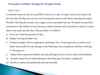
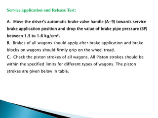
1. Performing a rake test using a test rig to check brake functionality across an entire train of wagons, including checking for leaks, applying and releasing brakes, and piston strokes.
2. Conducting a single wagon test using a test rig to test the air brake system on an individual wagon. This includes leakage testing, brake application and release testing, and adjusting slack adjusters.
3. The tools and equipment needed for rake and single wagon testing, including test rigs, pressure gauges, and spanners.
This document provides details about Ashutosh Khaitan's six-week industrial training at the Coach Care Centre in Old Delhi railway station from June-July 2013. It includes a training schedule, acknowledgements, abbreviations used, and an introduction to the Coach Care Centre and its role in railway maintenance. The bulk of the document describes procedures for intermediate overhauling of coaches, air brake system maintenance and repair, brake down maintenance, and washing line maintenance.
The document provides an overview of the process of mid-life rehabilitation (MLR) of railway coaches at the Coach Rehabilitation Workshop in Bhopal, India. The MLR process involves completely stripping and repairing coaches that are 12-15 years old. Key steps include separating the bogie and shell, stripping components to identify corrosion, heavy corrosion repair, painting, refurbishing interior furnishings, and reassembling. Specialized shops support each step of the process, from lifting and stripping, to body repair, painting, carpentry works, and reinstallation of components. Upon completion, coaches undergo testing before returning to service with an "as new" condition.
The document is a training report on an air brake system submitted by Vishal Singh from GB Pant Engineering College. It includes an acknowledgement, table of contents, and sections on the brief about the training, classification of engines, introduction to the diesel loco shed, directly assisting sections, and a project study on air brake systems. The project study section includes introductions to straight air brakes and working pressures, descriptions of operations and types of air brake systems like 28 LAV 1 and IRAB 1 used on Indian Railways locomotives, and explanations of components like the expressor, distributor valve, and types of valves. It discusses overhauling procedures, potential issues like brake binding, and developments in other countries.
The document discusses various types of CASNUB bogies used in Indian railways. It provides details of the components and features of CASNUB -22W, -22W(M), -22W(Retrofitted), -22NL, -22NLB, -22NLM, and -22HS bogies. The bogies comprise side frames, a bolster, springs, a centre pivot arrangement, friction plates, and other components. The document also outlines inspection and maintenance criteria for key bogie components like the adapter and side frames.
SUMMER TRAINING PPTOnCoach Care Centre (SICK LINE) Amit Verma
This document discusses the maintenance schedules and processes for different types of coaches in India. It provides the following key details:
1. Coaches are classified as minor, medium or major depending on their capacity of 50-100, 100-250, or above 250 passengers respectively.
2. Maintenance depots are categorized as integral coach factory (ICF), rail coach factory (RCF), link holfmann bushh (LHB), or hybrid depending on the coach design and components.
3. Regular maintenance includes washing after every trip and sick line maintenance on monthly, quarterly, or six month schedules depending on the coach category.
4. The sick line workshop performs repairs and overhauls like
North Western Indian Railway,Jaipur, Rajasthan 2016Awanish Kumar
The document provides information about North Western Railway located in Jaipur, India. It discusses the organisation structure, zones of Indian Railways including North Western Railway. It describes departments of Indian Railways and their roles. It provides details about wheels, machine shop, braking system and bogie shop used for maintenance of trains. It summarizes the types of maintenance schedules for trains. The spring shop section repairs and tests helical springs.
This document provides a training report on air brake systems used in railways. It describes the components and functioning of single pipe and twin pipe air brake systems. It discusses the limitations of single pipe systems and how twin pipe systems address these issues. It also outlines procedures for testing air brake systems, maintaining different components, and ensuring trains are safe to operate.
This is the hand book made by Jhansi Division of Indian Railways for the benefit of Railwaymen in particular to the staff involved in C&W maintenance. Excellent effort by the team.
The document provides details on the design features of a bogie, including its frame, materials used, imported bogie items, suspensions, wheels, brakes, and problems reported. It describes the bogie's primary and secondary suspensions, which use springs, dampers, and other components to connect the wheel set to the bogie frame and vehicle body. The document also lists specifications, dimensions, and condemning limits for various bogie parts.
The document provides information about the Carriage and Wagon workshop in Alambagh, Lucknow. It discusses the workshop's history and facilities. The workshop specializes in overhauling, repairing, and restoring coaches and wagons. It performs maintenance like wheel replacement, brake testing, and suspension oil changes. The document also describes different types of coaches and rolling stock, as well as the various levels of train maintenance.
Indian railways mechanical vocational training report 1 haxxo24 i~ihaxxo24
Indian Railways was previously transporting passengers using coaches designed by ICF that had limitations in speed, corrosion resistance, ride comfort, and part wear. To address this, it began procuring LHB coaches from Alstom featuring superior passenger experience, safety, and maintenance needs. Key benefits of LHB coaches include higher capacity, lower weight, reduced corrosion, lower maintenance requirements, and improved aesthetics, comfort, and safety. They use advanced materials, designs, and manufacturing techniques.
Handbook on maintenance of air brake system in lhb coaches (ftil type)SrinivasaRao Guduru
This document provides a maintenance handbook for the air brake system used in Indian Railways' LHB coaches. It covers the introduction, key features, principles of operation, parts lists, descriptions and maintenance procedures for the various components that make up the air brake system. The system uses a twin pipe graduated release design with additional safety features such as a brake panel, distributor valve, relay valve, brake pipe accelerator valve and passenger emergency valves. Disc brakes are mounted on each wheel and the system aims to provide safe and reliable braking performance for high-speed trains.
The document provides information on the Bogie Mounted Brake System (BMBS) introduced for freight stock in India.
It describes the key features of BMBS, which includes two 10" brake cylinders per wagon with integrated double acting slack adjusters to provide reliable braking performance. BMBS can be easily fitted to existing bogies without modifications. It also reduces wear on shoes and wheels through its parallelogram design that aligns braking forces.
The document explains the working of the single and twin pipe air brake systems used on Indian freight stock. It describes the charging, application and release stages. BMBS includes an automatic pressure modification valve to enable two-stage braking for loaded
The document discusses the bogie, which is an independent unit used under coaches that is mounted on wheels. It provides details on various types of bogies used in India, including IRS, SCHLIEREN, MAN-HAL, ICF All Coiled, IR-20, and FIAT bogies. The ICF bogie continues to be produced and used widely. Key components of the ICF bogie are described, including the bolster, side bearers, center pivot, bogie frame, wheel/axle, body-bogie joint, and primary/secondary suspension systems. Limitations are noted regarding flexibilities, vertical space constraints, and headstock yaw inertia.
This document is a training report submitted by Turendar Sahu to fulfill requirements for a Bachelor of Technology degree. It provides an overview of Sahu's 4-week training at the South East Central Railway in Bilaspur, India. The report includes sections on the company profile, LHB coaches, types of coaches, couplers, and other technical aspects of the railway systems that Sahu learned about during the training.
I had done 1 month summer training on topic " AIR BRAKE SYSTEM USED IN LOCOMOTIVE " from LOCO workshop, LKO....students who are doing so....this file can help them to prepare project file...
The document announces a revision to the maintenance pattern for coaching trains on Indian Railways. Coaching trains may now be permitted to run up to 3500 km in a round trip with terminal attention at the other end in lieu of mandatory pit line maintenance. Mandatory conditions for round trips up to 2500 km will also apply to trips up to 3500 km. Railways must ensure facilities exist for proper terminal attention and internal coach cleaning. The CMEs of both the base depot and terminal attention railways must certify facilities meet conditions before 3500 km round trips are permitted.
South east central railway (secr) bilaspur mechanical vocational training rep...haxxo24
Indian Railways operates the fourth largest railway network globally. It carries over 30 million passengers and 2.8 million tons of freight daily, earning $20.8 billion in 2011-2012. The ICF bogie is a conventional bogie used on Indian Railway passenger coaches. It has a fabricated steel frame and uses helical springs and roller bearings for suspension. The bogie transfers the weight of the coach to its wheels through side bearers and a pivoting bolster.
1. The APM device is placed between the bogie side frame and wagon underframe and senses the gap only during air brake application.
2. It restricts the brake cylinder pressure to 2.2 ± 0.25 Kg/cm2 for empty wagons and 3.8 ± 0.1 Kg/cm2 for loaded wagons.
3. The APM has a factory setting of 104mm for the sensor point movement between the loaded and empty zones.
This document provides an overview of an air brake system project report submitted for a Bachelor of Technology degree. It includes an acknowledgment, certificate, abstract, and index sections. The main body of the report then discusses various components of an air brake system used in commercial vehicles, including air hoses, cut off angle cocks, brake cylinders, dirt collectors, auxiliary reservoirs, and more. It provides diagrams to illustrate the components and their functions within the overall air brake system.
The document discusses various types of air brake systems used in trains. It begins with an introduction to developments in air brake systems, including twin pipe and automatic load sensing systems. It then describes the classification of air brake systems as direct or graduated release, and as single or twin pipe. The key components and working of a graduated twin pipe air brake system are explained. Advantages of twin pipe systems include improved braking performance and reduced drag on the train.
This document provides maintenance instructions for air suspension systems used on Indian Railways coaches. It describes the working principle of pneumatic suspension and its advantages over coil suspension. It includes details on the construction and components of air springs, as well as the schematic layout of the pneumatic suspension control equipment. Procedures are provided for inspection, maintenance and repair of air springs, pipes, and related components. Guidelines are also given for adjusting bogie clearances and buffer coupler heights when using air suspension.
The document provides information about maintenance schedules for Indian railway coaches. It discusses periodic overhauling that occurs every 18 months to renew coaches. Key components maintained include wheels and profiles, axles, air brake systems, and toilets. Various coach types like ICF and LHB are outlined, along with their dimensions and materials. Maintenance of bogies, coach bodies, windows, and water tanks is also summarized.
The document discusses various types of bogies and suspension systems used in Indian railways. It provides details of the CASNUB bogie, including its general description and features. The CASNUB bogie assembly consists of various components like side frames, bolster, spring plank, wheels, axles, axle boxes, and center pivot arrangement. Construction and maintenance details are provided for each of these components. Wear limits and tolerances for replacement are also specified.
Roller bearing used in railway coachessachin deora
This presentation is useful for that every person who complete their summer training under Railway Carriage Workshops For fulfillment for award of degree of B.Tech.
Air springs use compressed air inside a rubber bellow to provide suspension for coaches. This allows the coach to maintain a constant height regardless of passenger load. Air springs were introduced for hybrid coaches because heavy passenger loads would compress main springs and damage coil springs, compromising passenger comfort. The air spring system uses a height monitoring valve to add or release air as needed to maintain the required buffer height. When loads change, the air spring initially adjusts its distance from the coach body and then the valve adjusts air pressure until the proper height is reached. Maintenance of the air spring system requires trained staff and spare parts available at stations.
The document is a four week industrial training report submitted by Deewan Singh to the Department of Mechanical Engineering at GLA University in Mathura. It provides an overview of Singh's training at the Division Carriage & Wagon Depot in Agra, including declarations, acknowledgements and a table of contents covering topics like the role of Carriage & Wagon in railways, types of coaches like ICF and LHB, bogie components, wheel defects and more.
The document provides an introduction and overview of the updated Indian Railways Unified Maintenance Manual for Wagons. Some key points:
- The previous maintenance manual was published in 1979 and did not cover air brake systems, which have since been introduced.
- A committee was formed in 1998 to revise and update the manual to reflect modern wagon designs, maintenance strategies, and technological upgrades across Indian Railways.
- The updated manual provides comprehensive maintenance instructions for all wagon systems, with a focus on air brake systems. It is intended to serve as a single reference for wagon maintenance.
- Standardized numbering conventions are used for chapters, paragraphs, figures and tables to facilitate future revisions as new stock is introduced.
The document provides procedures for rake testing freight stock. Key steps include:
1. Conducting a visual inspection of the rake and repairing any defects.
2. Attaching a portable test rig or locomotive to the rake and testing for continuity and leaks in the brake and feed pipes.
3. Performing a service brake application and release test to check brake cylinder strokes and that brakes apply properly.
4. Ensuring at least 90% of brake cylinders are operative on the rake.
This document provides information about an industrial training completed at the Coach Care Centre in Old Delhi Railway Station from June to July 2016. It includes a training schedule, list of tasks completed during four weeks of training, and information about maintenance activities like intermediate overhauling and air brake testing conducted at the Coach Care Centre. The training covered maintenance of air brake systems, brake down maintenance, and washing line maintenance of coaches.
South east central railway (secr) bilaspur mechanical vocational training rep...haxxo24
The document is a project report submitted by Bhasker Harangaonker detailing his summer vocational training with the South East Central Railway in Bilaspur from May 20th to June 20th 2011. It includes sections on the objectives and institutions involved in the training. It also provides details on topics covered during the training, including the major sick line, BCN depot, air brakes, slack adjusters, and routine and periodic overhauling of wagons. The report is presented over multiple pages with an index of topics covered.
The document provides details about a project report submitted after an industrial training at Coach Care Centre in Delhi. It includes:
1) A training schedule covering maintenance of coaches over 1-2 weeks including IOH of primary based coaches and repairing of air brake systems.
2) An introduction to the Coach Care Centre and its modern facilities for maintenance of coaches.
3) Descriptions of the maintenance procedures for coaches, including activities in IOH like buffer maintenance, suspension maintenance, and air brake system maintenance.
The document provides information about Research Designs and Standards Organization (RDSO) in India and air brake systems used on Indian railways. It discusses the working, components, and advantages of the air brake system. It also describes an air brake system test rig used to test brake equipment performance and its capabilities. Additional topics covered include fatigue testing of bogie frames, different types of couplings used, and an overview of air suspension systems.
1. Air suspension uses pressurized air in rubber bellows to provide cushioning and ride quality on trains, replacing steel coil springs.
2. It provides better riding comfort and can sustain higher loads than traditional steel coil springs.
3. The key components of an air suspension system include air springs, leveling valves, reservoirs, and isolating cocks to control the flow of compressed air.
The document provides information about the emission control system for a 2004 Land Cruiser, including:
- Descriptions of the main components and functions of the positive crankcase ventilation (PCV) system, evaporative emission (EVAP) control system, and three-way catalytic converter (TWC) system.
- Inspection procedures for each system, such as checking hoses and connections for the PCV system, performing vacuum and pressure tests on the EVAP system, and inspecting the exhaust assembly and TWC for the catalytic converter system.
- Diagrams showing the layout and connections of parts for each emission control system.
Indian Railways Training on Coach Care CentreRao Khola
The document summarizes maintenance procedures for Indian railway coaches. Coaches receive secondary maintenance every 2500 km which includes washing, cleaning, and brake testing. More extensive primary maintenance is done every 6 hours and includes tasks like oil changes and wheel inspections. Major maintenance is done in the sick line workshop and can include works like separating coaches from bogies for repair. Platform train duty involves safety checks before departure including axle temperature checks and verifying the brake power certificate.
Pamphlet on air suspension system fitted on hybrid coachesSrinivasaRao Guduru
The document provides information on air suspension systems used on Indian Railways hybrid coaches. It describes the main components of the air suspension system, including air springs, levelling valves, reservoirs, and isolating cocks. It also outlines inspection and maintenance procedures, such as checking air springs for leaks and draining reservoirs. Operating instructions are given for train drivers, such as maintaining air pressure and isolating leaky bogies or coaches by closing isolating cocks and limiting train speed.
This document provides operation and maintenance instructions for the Powermaster FMP-8000 tube end facing machine. The summary is:
The Powermaster FMP-8000 is a pneumatic tube end facing machine with a weight of 27kg and a tube ID range of 50-203mm. The document provides assembly instructions, operation instructions, specifications for the pneumatic drive and parts, maintenance guidelines for the air motor, troubleshooting tips, and jaw selection charts. Safety warnings and lubrication recommendations are also included to properly operate and service the machine.
Various Mechanical Units Involved in The Bottling Of LPG cylindersMohit Dhull
LPG BOTTLING PLANTS
MECHANICAL UNITS INVOLVED IN THE PROCESS OF FILLING OF LPG CYLINDERS
REFERENCES USED
LPG DETAILS ,RECOVERY,PRODUCTION
FIRE SAFETY SYSTEMS
2003 TOYOTA CELICA Service Repair Manualjsemd suekd
This is the Highly Detailed factory service repair manual for the2003 TOYOTA CELICA, this Service Manual has detailed illustrations as well as step by step instructions,It is 100 percents complete and intact. they are specifically written for the do-it-yourself-er as well as the experienced mechanic.2003 TOYOTA CELICA Service Repair Workshop Manual provides step-by-step instructions based on the complete dis-assembly of the machine. It is this level of detail, along with hundreds of photos and illustrations, that guide the reader through each service and repair procedure. Complete download comes in pdf format which can work under all PC based windows operating system and Mac also, All pages are printable. Using this repair manual is an inexpensive way to keep your vehicle working properly.
Service Repair Manual Covers:
Introduction
Maintenance
Preparation
Service Specifications
Diagnositics
Engine Mechanical
Emission Control
SFI
Cooling
Lubrication
Ignition
Starting
Charging
Clutch
C56 Manual Transaxle
C60 Manual Transaxle
U240E Automatic Transaxle
U341E Automatic Transaxle
Suspension and Axle
Brake
Steering
Supplemental Restraint System
Body Electrical
Body
Air Conditioning
Alphabetical Index
File Format: PDF
Compatible: All Versions of Windows & Mac
Language: English
Requirements: Adobe PDF Reader
NO waiting, Buy from responsible seller and get INSTANT DOWNLOAD, Without wasting your hard-owned money on uncertainty or surprise! All pages are is great to have2003 TOYOTA CELICA Service Repair Workshop Manual.
Looking for some other Service Repair Manual,please check:
https://www.aservicemanualpdf.com/
Thanks for visiting!
2002 TOYOTA CELICA Service Repair Manualjksmttemmd
This is the Highly Detailed factory service repair manual for the2002 TOYOTA CELICA, this Service Manual has detailed illustrations as well as step by step instructions,It is 100 percents complete and intact. they are specifically written for the do-it-yourself-er as well as the experienced mechanic.2002 TOYOTA CELICA Service Repair Workshop Manual provides step-by-step instructions based on the complete dis-assembly of the machine. It is this level of detail, along with hundreds of photos and illustrations, that guide the reader through each service and repair procedure. Complete download comes in pdf format which can work under all PC based windows operating system and Mac also, All pages are printable. Using this repair manual is an inexpensive way to keep your vehicle working properly.
Service Repair Manual Covers:
Introduction
Maintenance
Preparation
Service Specifications
Diagnositics
Engine Mechanical
Emission Control
SFI
Cooling
Lubrication
Ignition
Starting
Charging
Clutch
C56 Manual Transaxle
C60 Manual Transaxle
U240E Automatic Transaxle
U341E Automatic Transaxle
Suspension and Axle
Brake
Steering
Supplemental Restraint System
Body Electrical
Body
Air Conditioning
Alphabetical Index
File Format: PDF
Compatible: All Versions of Windows & Mac
Language: English
Requirements: Adobe PDF Reader
NO waiting, Buy from responsible seller and get INSTANT DOWNLOAD, Without wasting your hard-owned money on uncertainty or surprise! All pages are is great to have2002 TOYOTA CELICA Service Repair Workshop Manual.
Looking for some other Service Repair Manual,please check:
https://www.aservicemanualpdf.com/
Thanks for visiting!
8
1. Set the No. 1 cylinder to top dead center and measure the valve clearances.
2. Determine the required new valve lifter size using charts or calculations based on the measured clearance.
3. Remove the camshafts and timing components and tie up the timing chain. Also remove the valve lifters.
4. Replace the valve lifters with new ones matching the required size to adjust the clearance. Reinstall all components.
2001 TOYOTA CELICA Service Repair Manualjkmsrremmd
This is the Highly Detailed factory service repair manual for the2001 TOYOTA CELICA, this Service Manual has detailed illustrations as well as step by step instructions,It is 100 percents complete and intact. they are specifically written for the do-it-yourself-er as well as the experienced mechanic.2001 TOYOTA CELICA Service Repair Workshop Manual provides step-by-step instructions based on the complete dis-assembly of the machine. It is this level of detail, along with hundreds of photos and illustrations, that guide the reader through each service and repair procedure. Complete download comes in pdf format which can work under all PC based windows operating system and Mac also, All pages are printable. Using this repair manual is an inexpensive way to keep your vehicle working properly.
Service Repair Manual Covers:
Introduction
Maintenance
Preparation
Service Specifications
Diagnositics
Engine Mechanical
Emission Control
SFI
Cooling
Lubrication
Ignition
Starting
Charging
Clutch
C56 Manual Transaxle
C60 Manual Transaxle
U240E Automatic Transaxle
U341E Automatic Transaxle
Suspension and Axle
Brake
Steering
Supplemental Restraint System
Body Electrical
Body
Air Conditioning
Alphabetical Index
File Format: PDF
Compatible: All Versions of Windows & Mac
Language: English
Requirements: Adobe PDF Reader
NO waiting, Buy from responsible seller and get INSTANT DOWNLOAD, Without wasting your hard-owned money on uncertainty or surprise! All pages are is great to have2001 TOYOTA CELICA Service Repair Workshop Manual.
Looking for some other Service Repair Manual,please check:
https://www.aservicemanualpdf.com/
Thanks for visiting!
8
This document provides instructions for restoring a machine after service work. It includes steps to reinstall underbody skid plates, clean work surfaces, start the engine and bleed air from the fuel system if needed, check filter and drain plug seals, test run the machine, check and top up fluid levels, operate the hydraulic suspension if oil was changed, and use a computer to read and erase error codes and reset service messages. The restoration process ensures the machine is ready for operation after maintenance or repairs.
This document provides instructions for adjusting valves, unit injectors, and brake rocker arms on an engine. It involves rotating the engine to specific markings, checking clearances, and adjusting components as needed using tools and torque specifications. Safety precautions and service position steps are outlined. Replacement of diesel particulate filters and ignition cables are also described, including necessary parts, markings, and safety procedures.
This document provides instructions for restoring a machine after service work. It includes steps to reinstall underbody skid plates, clean work surfaces, start the engine and bleed air from the fuel system if needed, check filter and drain plug seals, test run the machine, check and top up fluid levels, operate the hydraulic suspension if oil was changed, and use a computer to read and erase error codes and reset service messages. The restoration process ensures the machine is ready for operation after maintenance or repairs.
The LHB bogie is a type of railroad freight car truck or bogie. It was developed in the 1950s by the American Locomotive Company (ALCO) and has become the standard bogie design used on most modern freight cars in North America due its durability and ability to carry heavy loads at high speeds. The LHB bogie features a bolster suspension system, uses fewer parts than previous designs, and helped increase freight car payloads.
The document discusses troubleshooting an air brake system. It outlines remedial measures that can be taken to address issues with the air brake system. The document concludes by thanking the reader.
INTRODUCTION OF CARRIAGE & WAGON, VARIOUS TYPES OF WAGON TCCW1
This document provides classifications and descriptions of various types of rolling stock used in Indian Railways. It discusses wagons for transporting goods like open wagons for coal and ore, covered wagons for bagged commodities, flat wagons for steel products, and hopper wagons for discharging materials from the bottom. It also describes passenger coaches and different types of bogies used in wagons. Specific wagons are explained including their year of design, payload capacity, suspension type, identification features, and maximum speed.
Chapter wise All Notes of First year Basic Civil Engineering.pptxDenish Jangid
Chapter wise All Notes of First year Basic Civil Engineering
Syllabus
Chapter-1
Introduction to objective, scope and outcome the subject
Chapter 2
Introduction: Scope and Specialization of Civil Engineering, Role of civil Engineer in Society, Impact of infrastructural development on economy of country.
Chapter 3
Surveying: Object Principles & Types of Surveying; Site Plans, Plans & Maps; Scales & Unit of different Measurements.
Linear Measurements: Instruments used. Linear Measurement by Tape, Ranging out Survey Lines and overcoming Obstructions; Measurements on sloping ground; Tape corrections, conventional symbols. Angular Measurements: Instruments used; Introduction to Compass Surveying, Bearings and Longitude & Latitude of a Line, Introduction to total station.
Levelling: Instrument used Object of levelling, Methods of levelling in brief, and Contour maps.
Chapter 4
Buildings: Selection of site for Buildings, Layout of Building Plan, Types of buildings, Plinth area, carpet area, floor space index, Introduction to building byelaws, concept of sun light & ventilation. Components of Buildings & their functions, Basic concept of R.C.C., Introduction to types of foundation
Chapter 5
Transportation: Introduction to Transportation Engineering; Traffic and Road Safety: Types and Characteristics of Various Modes of Transportation; Various Road Traffic Signs, Causes of Accidents and Road Safety Measures.
Chapter 6
Environmental Engineering: Environmental Pollution, Environmental Acts and Regulations, Functional Concepts of Ecology, Basics of Species, Biodiversity, Ecosystem, Hydrological Cycle; Chemical Cycles: Carbon, Nitrogen & Phosphorus; Energy Flow in Ecosystems.
Water Pollution: Water Quality standards, Introduction to Treatment & Disposal of Waste Water. Reuse and Saving of Water, Rain Water Harvesting. Solid Waste Management: Classification of Solid Waste, Collection, Transportation and Disposal of Solid. Recycling of Solid Waste: Energy Recovery, Sanitary Landfill, On-Site Sanitation. Air & Noise Pollution: Primary and Secondary air pollutants, Harmful effects of Air Pollution, Control of Air Pollution. . Noise Pollution Harmful Effects of noise pollution, control of noise pollution, Global warming & Climate Change, Ozone depletion, Greenhouse effect
Text Books:
1. Palancharmy, Basic Civil Engineering, McGraw Hill publishers.
2. Satheesh Gopi, Basic Civil Engineering, Pearson Publishers.
3. Ketki Rangwala Dalal, Essentials of Civil Engineering, Charotar Publishing House.
4. BCP, Surveying volume 1
it describes the bony anatomy including the femoral head , acetabulum, labrum . also discusses the capsule , ligaments . muscle that act on the hip joint and the range of motion are outlined. factors affecting hip joint stability and weight transmission through the joint are summarized.
LAND USE LAND COVER AND NDVI OF MIRZAPUR DISTRICT, UPRAHUL
This Dissertation explores the particular circumstances of Mirzapur, a region located in the
core of India. Mirzapur, with its varied terrains and abundant biodiversity, offers an optimal
environment for investigating the changes in vegetation cover dynamics. Our study utilizes
advanced technologies such as GIS (Geographic Information Systems) and Remote sensing to
analyze the transformations that have taken place over the course of a decade.
The complex relationship between human activities and the environment has been the focus
of extensive research and worry. As the global community grapples with swift urbanization,
population expansion, and economic progress, the effects on natural ecosystems are becoming
more evident. A crucial element of this impact is the alteration of vegetation cover, which plays a
significant role in maintaining the ecological equilibrium of our planet.Land serves as the foundation for all human activities and provides the necessary materials for
these activities. As the most crucial natural resource, its utilization by humans results in different
'Land uses,' which are determined by both human activities and the physical characteristics of the
land.
The utilization of land is impacted by human needs and environmental factors. In countries
like India, rapid population growth and the emphasis on extensive resource exploitation can lead
to significant land degradation, adversely affecting the region's land cover.
Therefore, human intervention has significantly influenced land use patterns over many
centuries, evolving its structure over time and space. In the present era, these changes have
accelerated due to factors such as agriculture and urbanization. Information regarding land use and
cover is essential for various planning and management tasks related to the Earth's surface,
providing crucial environmental data for scientific, resource management, policy purposes, and
diverse human activities.
Accurate understanding of land use and cover is imperative for the development planning
of any area. Consequently, a wide range of professionals, including earth system scientists, land
and water managers, and urban planners, are interested in obtaining data on land use and cover
changes, conversion trends, and other related patterns. The spatial dimensions of land use and
cover support policymakers and scientists in making well-informed decisions, as alterations in
these patterns indicate shifts in economic and social conditions. Monitoring such changes with the
help of Advanced technologies like Remote Sensing and Geographic Information Systems is
crucial for coordinated efforts across different administrative levels. Advanced technologies like
Remote Sensing and Geographic Information Systems
9
Changes in vegetation cover refer to variations in the distribution, composition, and overall
structure of plant communities across different temporal and spatial scales. These changes can
occur natural.
हिंदी वर्णमाला पीपीटी, hindi alphabet PPT presentation, hindi varnamala PPT, Hindi Varnamala pdf, हिंदी स्वर, हिंदी व्यंजन, sikhiye hindi varnmala, dr. mulla adam ali, hindi language and literature, hindi alphabet with drawing, hindi alphabet pdf, hindi varnamala for childrens, hindi language, hindi varnamala practice for kids, https://www.drmullaadamali.com
Gender and Mental Health - Counselling and Family Therapy Applications and In...PsychoTech Services
A proprietary approach developed by bringing together the best of learning theories from Psychology, design principles from the world of visualization, and pedagogical methods from over a decade of training experience, that enables you to: Learn better, faster!
Communicating effectively and consistently with students can help them feel at ease during their learning experience and provide the instructor with a communication trail to track the course's progress. This workshop will take you through constructing an engaging course container to facilitate effective communication.
Philippine Edukasyong Pantahanan at Pangkabuhayan (EPP) CurriculumMJDuyan
(𝐓𝐋𝐄 𝟏𝟎𝟎) (𝐋𝐞𝐬𝐬𝐨𝐧 𝟏)-𝐏𝐫𝐞𝐥𝐢𝐦𝐬
𝐃𝐢𝐬𝐜𝐮𝐬𝐬 𝐭𝐡𝐞 𝐄𝐏𝐏 𝐂𝐮𝐫𝐫𝐢𝐜𝐮𝐥𝐮𝐦 𝐢𝐧 𝐭𝐡𝐞 𝐏𝐡𝐢𝐥𝐢𝐩𝐩𝐢𝐧𝐞𝐬:
- Understand the goals and objectives of the Edukasyong Pantahanan at Pangkabuhayan (EPP) curriculum, recognizing its importance in fostering practical life skills and values among students. Students will also be able to identify the key components and subjects covered, such as agriculture, home economics, industrial arts, and information and communication technology.
𝐄𝐱𝐩𝐥𝐚𝐢𝐧 𝐭𝐡𝐞 𝐍𝐚𝐭𝐮𝐫𝐞 𝐚𝐧𝐝 𝐒𝐜𝐨𝐩𝐞 𝐨𝐟 𝐚𝐧 𝐄𝐧𝐭𝐫𝐞𝐩𝐫𝐞𝐧𝐞𝐮𝐫:
-Define entrepreneurship, distinguishing it from general business activities by emphasizing its focus on innovation, risk-taking, and value creation. Students will describe the characteristics and traits of successful entrepreneurs, including their roles and responsibilities, and discuss the broader economic and social impacts of entrepreneurial activities on both local and global scales.
2. A schematic layout of rake test rig (RTR) is shown in. A rake of wagon stock can be tested with
this Test Rig. This Rig may also be used for testing the train in yards before attaching the engine.
The Rake Test Rig unit consists of air supply system and mobile test rig. The details are provided
in Annexure-I The mobile test rig is having a cubical structure and is mounted on wheels. It can be
taken to the yards and sick lines. The procedure is as follows:
A. Carry out Visual Examination of rake.
B. Prepare Test Rig for Rake Test.
C. Conduct Leakage, Service Application and Release Test. Visual inspection is a check of air
brake sub-assembly for any damage on the brake pipe, hose coupling etc and then rectifying
it. The steps are :-
i) Inspect loose suspension brackets and anti-pilferage devices of all air brake sub-assemblies.
ii) Visually inspect for any defect/damage in the brake pipe, hose pipe, coupling etc.
iii) Rectify or replace the problematic part/sub-assembly.
Procedure of Rake Testing for Freight Stock
Rake Test :
3. Rake Test can be performed by using a portable device called „Test Rig‟ or by Locomotive.
The Test Rig provides all facilities like locomotive to conduct the test. The source of
compressed air supply to the Test Rig is through a compressor installed in the wagon depot
for Brake Pipe and Feed Pipe of the test rig. The Air Dryer should also be provided just
before connecting brake pipe and feed pipe for air supply system and Mobile test Rig.
Attach the rake test rig to the rake through the couplings. Carry out following tests as per the
procedure given in G-97 Annexure-XI {MP guide No.11 (Rev.01) amendment No.01 of Jan-
2010} for checking capability of locomotives for Charging/Releasing of train brakes,
checking of leakage in the train, checking leakage in feed pipe, brake cylinder operative
percentage, and procedure to be followed at way side.
4. Following examination must be carried out before rake testing
Hand Brakes of all wagons are fully released.
Operating handle of empty load box is in correct position i.e. 'Empty' position when
wagon is empty or lightly loaded and in 'Loaded' position when wagon is loaded beyond
the specified value.
Hose couplings of brake pipe & feed pipe on consequent wagons are coupled to one
another to form a continuous air passage from the locomotive to the rear end of train.
All the angle cocks except those at the rear end of the train are kept OPEN.
Hose coupling at the rear end of the train is placed on hose coupling support.
Isolating cocks of Distributor Valve on all wagons are in OPEN position.
5. Checking of Continuity and Leakage in Rake:
A. Attach the Diesel/Electric locomotive/Test Rig to the rake fitted with twin pipe air
brake system and couple brake pipes and feed pipes. Ensure correct coupling with
brake and feed pipe in a manner that there is no leakage of air from coupled joints.
B. The coupling should be done with angle cocks in closed position.
C. Open the angle cocks of loco after coupling feed pipe and brake pipe.
D. Open the angle cock of the brake pipes and the feed pipes on all the wagons and
check for continuity and leakage of brake pipe and feed pipe by reducing and
rebuilding brake pipe and feed pipe pressure operating by A9 brake valve & angle
cock fitted in feed pipe on locomotive (on wagon side) respectively. The verification
should invariably to be carried out through the pressure gauges (BP& FP) provided in
Guard's Brake Van.
6. NOTE: If the pressure is not within specified limit as given
above then check for leakage in rake and correct it.
7.
8. Leakage Rate Test:
E. After the stabilizing pressure as given in above table, move the driver's automatic
brake valve handle (A-9) towards application position to reduce brake pipe pressure
from 5.0 kg/cm² to 4.0 kg/cm².
F. After the brake pipe pressure has been stabilized –
i) Close the brake pipe isolating cock provided between additional C2W Relay valve
and brake pipe of the locomotive or isolating cock of Test Rig for checking BP leakage.
ii) Close the isolating cock provided between feed valve and feed pipe of the locomotive
or isolating cock of FP for checking FP leakage.
G. Wait for 60 sec for temperature and gauge settlement then note the drop in pressure
in brake pipe & feed pipe pressure gauge in locomotive for 05 minutes.
H. The drop in brake pipe & feed pipe pressure gauge shall not be more than 0.25
kg/cm²/min. If the leakage rate is more than the value indicated in (H), check for
excessive leakage on individual wagon as indicated below –
9. 1. A hissing sound would be audible at points where leakage is heavy.
2. Once the hissing sound is heard from a particular area, pin-point the location of leakage by
applying soap water solution.
3. Use permitted material viz. Teflon tape for arresting the leakage.
I. In case leakage is heavy and cannot be arrested, the wagon may have to be isolated/detached.
J. In case where leakage can be arrested temporarily by tap and the nature of leakage is such
that it requires attention at primary depot, clear marking on the wagon should be done to draw
attention of primary depot for adequate attention.
K. In case the leakage is from the distributor valve and cannot be arrested, isolation of the
wagon can be carried out by closing the distributor valve isolating cock. In such condition, clear
marking should be provided on the wagon to indicate this defect to primary depot. Do not close
brake pipe angle cocks under any circumstances, either for isolation of wagons or for any
purpose whatsoever, except for carrying out shunting operation after which the angle cocks
should again be opened to ensure continuity of brake pipe.
10. Service application and Release Test:
A. Move the driver's automatic brake valve handle (A-9) towards service
brake application position and drop the value of brake pipe pressure (BP)
between 1.3 to 1.6 kg/cm².
B. Brakes of all wagons should apply after brake application and brake
blocks on wagons should firmly grip on the wheel tread.
C. Check the piston strokes of all wagons. All Piston strokes should be
within the specified limits for different types of wagons. The piston
strokes are given below in table.
11. If the piston stroke is incorrect then, record “A” Dimension, it should be 70 ±20 mm in
empty and loaded condition.
D. Check all brake cylinders. Wagons with in-operative brake cylinders should be
marked unfit and detached.
E. After the release of brake, the piston of brake cylinder should be fully inside and
brake blocks
are free from the wheels.
F. Guard‟s emergency brake valve: Ensure that Guard Emergency brake valve is
working properly by operating it.
G. BPC (Brake Power Certificate): Ensure that Loco Pilot, Guard and TXR have
checked the details given in the certificate and signed for its compliance.
12. TOOLS AND EQUIPMENTS:
[1] Rake Test Rig/Locomotive.
[2] Open End spanner 18x19”
[3] Spanner 10 mm & 12 mm
13. SINGLE WAGON TEST
“Single wagon Test” is performed on a wagon to ensure proper functioning of the air
brake system. It is generally performed on the sick wagon attended in the sick line or
whenever a subassembly of the air brake system is replaced either in depot or
workshop. Single wagon test is also carried out after POH and after every change of
distributor valve in the workshop.
The different tests to be performed on the subassemblies of a wagon are as follows:
Test1: Leakage Test.
Test2: Sensitivity and Insensitivity Test.
Test3: Brake Application and Release Test.
Test4: Graduated Application and Release Test.
Test5: Check and adjust Slack Adjuster
SINGLE WAGON TEST
14. A. TOOLS AND EQUIPMENT
1. Test Rig
2. Spanners 10mm, 12mm
B. CONCEPT
Single Wagon Test is performed, by using a portable device called “Test Rig”. This test
rig provides all facilities similar to a driver‟s brake valve. The source of compressed air
for conducting the test is through a compressor installed in depots and workshops for
conducting various tests without the need of a locomotive. The part description and
specification are given in table below.
15. PROCEDURE FOR SINGLE WAGON TESTING (Single Pipe)
A systematic lay-out of Single Wagon Test Rig (SWTR) is shown in fig. 7.33. This SWTR
is utilised for testing the air brake system fitted on single wagon. The wagon should not
be connected with the locomotive at the time of testing. The following procedure shall be
followed for testing.
i. The wagon under testing is to be coupled at one end with the SWTR coupling head BP
and the other end should be closed with dummy coupling head. Pressure gauge should be
fitted on brake cylinder.
ii. Couple the SWTR to the main line of compressor.
iii. Place the isolating cock of distributor valve on the wagon in open position i.e., the
handle should be vertically down wards.
iv. Set the pressure reducing valve (1) to 5 + 0.1 Kg/cm2 Open the cocks (2) and (8) and
so the angle cocks on the both ends of the wagons. Move the driver‟s brake valve (3) in
the charging and release position.
16. v. Wait for about 5 minutes to charge the complete system.
vi . Check the pressure in BP pressure gauge (7). Pressure should be 5+ 0.1 Kg. /cm2 in
BP. If there is pressure drop in the gauge (7) detect the source of leakage and eliminate it.
vii. Close cocks (2) & (8). Check the leakage on BP for one minute.
viii. Open cock (2). Bring Driver‟s brake valve in full-service application position.
ix. Record the brake cylinder filling time from 0 to 3.6 Kg. /cm2 in brake cylinder
pressure gauge.
x. Record maximum pressure in brake cylinder.
xi. Record the pressure drop in BP from pressure gauge (4).
xii. Record the piston stroke of brake cylinder.
xiii. Bring Driver‟s brake valve in the charging and release position.
xiv. Record the brake cylinder draining time from 3.8 + 0.1 to 0.4 Kg. /cm2 in brake
cylinder pressure gauge & check complete release of brakes i.e., piston should reach its
initial position.
17. xvi. Open cock (6) for checking sensitivity of brakes. Record time within which brakes
get applied.
xvii. Close cock (6) and open cock (2). Wait till brakes are released.
xviii. Close cock (2) and open cock (7) for checking the insensitivity of brakes. The
brakes should not apply.
xix. Close cock (7) and (8) and open cock (2), BP pressure should rise to 5 Kg. /cm2
xx. Close cock (2) and open cock (5) for emergency application.
xxi. Record the brake cylinder charging time from 0 to 3.6 Kg. /cm2 in BC pressure
gauge.
xxii. Record maximum BC pressure.
xxiii. Check the leakage in BC for 5 minutes.
xxiv. Pull the manual release lever of distributor valve for about 10 sec. Brake cylinder
pressure should become zero automatically.
xxv. The above tests should be done in both empty and loaded condition.
xxvi. The results of test shall be recorded in the test proforma attached herewith
18. 10. Record the brake cylinder filling time from 0 to 3.6 kg/cm2 in brake cylinder pressure
gauge.
11. Record maximum pressure in brake cylinder.
12. Record the pressure drop in BP from pressure gauge (7).
13. Record the piston stroke of brake cylinder.
14. Bring Driver's brake valve in charging and release position.
15. Record the brake cylinder draining time from 3.8 to 0.4 kg/cm2 in brake cylinder
pressure gauge & check complete release of brakes i.e., piston should reach its initial
position.
16. Close cock (5) and open cock (11) for charging the reservoir to 5 kg/cm2
19. 17 Open cock (9) for checking sensitivity of brakes. Record the time
within which brakes applied.
18 close cock (9) and open cock (5). Wait till brakes are released.
19 Close cock (5) and open cock (10) for checking the insensitivity of
brakes.
20 Close cock (10) and (11) and open cock (5). BP pressure should rise
to 5 Kg/cm2.
21 Close cock (5) and open cock (8) for emergency application.
22 Record the brake cylinder charging time from 0 to 3.6 kg/cm2 in BC
pressure gauge.
23 Record maximum BC pressure.
24 Check the leakage in BC for 5 minutes.
25 The above tests should be done in both empty and loaded
condition.
26 The results of test shall be recorded in the test proforma as given
20. PROFORMA FOR SINGLE WAGON TEST FOR WAGONS OTHER THAN BOBR &
BOBRN (Single pipe/Twin pipe)